
 My Inquiry
 My Account


Microchip Technology MCW1001AT-I/SS
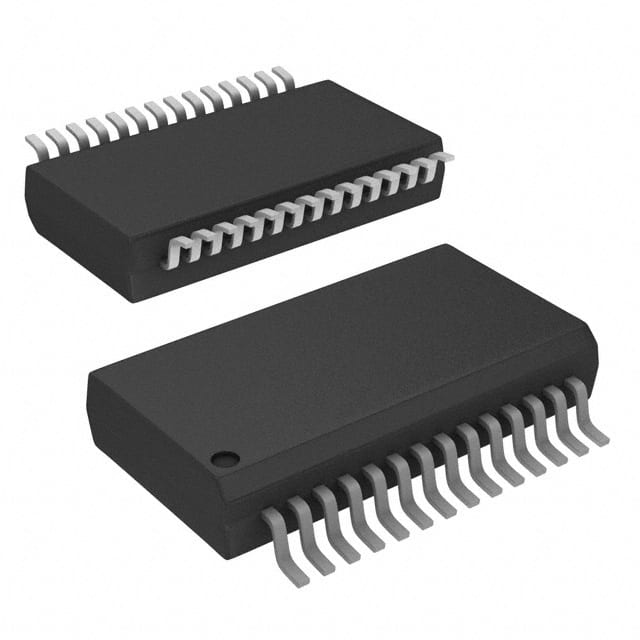
- Part No.:
- MCW1001AT-I/SS
- Manufacturer:
- Microchip Technology
- Category:
- Specialized
- Package:
- 28-SSOP (0.209", 5.30mm Width)
- Datasheet:
-
 MCW1001AT-I/SS.pdf
- Description:
- IC INTERFACE SPECIALIZED 28SSOP
- Quantity:
- Payment:

- Shipping:

Inventory:2,332
Please send an inquiry. Send us your inquiry, and we will respond immediately.
Product details
Overview
MCW1001AT-I/SS from Microchip Technology is a TCP/IP socket communications interface IC designed as a companion controller for the MRF24WB0MA/MB 802.11 Wi-Fi modules. It integrates an on-board TCP/IP stack, 802.11 connection manager, UART interface (up to 230 Kbaud), 8 GPIOs, and operates from 2.7V–3.6V. It enables embedded microcontrollers to implement Wi-Fi connectivity without external memory or protocol stack software.
For engineers reviewing the MCW1001AT-I/SS datasheet, MCW1001AT-I/SS pinout, MCW1001AT-I/SS application, or MCW1001AT-I/SS equivalent, key selection criteria include UART-based socket API support, SPI-controlled MRF24WB0M interfacing, industrial temperature operation (−40°C to +85°C), SSOP-28 packaging, and GPIO voltage tolerance differentiation (GPIO0–4: VDD-only; GPIO5–7: 5.5V-tolerant).
Technical Context
The MCW1001AT-I/SS implements a dedicated hardware abstraction layer between host microcontrollers and the MRF24WB0M 802.11 transceiver, using a proprietary WSPI interface (WCS, WRST, WHIB, WSDI/WSDO, WSCK, WINT) with precise timing control for Wi-Fi power management and connection state synchronization. Its internal TCP/IP stack supports BSD-style socket creation, binding, listening, connecting, sending, and receiving over UDP/TCP.
It relies on an external 8 MHz crystal oscillator (OSC1/OSC2), includes an internal voltage regulator stabilized by a 10 µF VCAP capacitor, and provides asynchronous event notification (e.g., IP assignment, Wi-Fi status change, scan completion) via UART to the host. Autobaud initialization uses 0x55 sync byte, and hardware flow control is supported via URTS/UCTS with buffer-level handshaking thresholds.
Key Specifications
| Parameter | Value and Actual Design Meaning |
|---|---|
| Operating Voltage | 2.7V–3.6V - Enables direct integration with 3.3V logic systems without level-shifting. |
| Temperature Range | −40°C to +85°C - Qualified for industrial environments including smart meters and HVAC controls. |
| UART Baud Rate | Up to 230 Kbaud - Supports high-throughput serial data exchange with host MCU over standard UART. |
| GPIO Count & Types | 8 I/O pins: GPIO0–4 (medium drive, VDD-limited input); GPIO5–7 (high-drive, 5.5V-tolerant input) - Enables mixed-voltage system interfacing and LED driving. |
| Oscillator Requirement | 8 MHz crystal (OSC1/OSC2) - Provides stable clock source for internal timing and Wi-Fi synchronization. |
| VCAP Capacitor | 10 µF low-ESR ceramic/tantalum - Required to stabilize internal LDO output; must not be connected to VDD. |
| Package | 28-pin SSOP (Small Outline Package) - Surface-mount footprint compatible with automated PCB assembly. |
Pinout & Package
MCW1001AT-I/SS is housed in a 28-pin Small Outline Package (SSOP) with 0.635 mm pitch and exposed pad-less construction. Pin numbering follows standard SSOP convention (pin 1 at top-left corner, counterclockwise).
| Pin/Terminal | Circuit Role | Design Meaning |
|---|---|---|
| RESET | Active-low reset input | Externally triggers full device initialization; includes internal noise filtering to reject glitches. |
| UTX / URX | UART transmit / receive | Full-duplex asynchronous serial interface; default 115200 baud, 8N2 format after reset. |
| URTS / UCTS | Hardware flow control | URTS (output) de-asserts at 499-character buffer threshold; UCTS (input) enables/disable transmission handshake. |
| GPIO0–GPIO7 | General-purpose digital I/O | GPIO0–4: medium-drive, VDD-referenced inputs; GPIO5–7: high-drive, 5.5V-tolerant inputs - supports mixed-voltage peripheral control. |
| WCS / WRST / WHIB / WSDI / WSDO / WSCK / WINT | WSPI interface to MRF24WB0M | Direct SPI-like control of Wi-Fi module: chip select, reset, hibernate, data I/O, clock, and interrupt signaling. |
| OSC1 / OSC2 | Crystal oscillator interface | Drives external 8 MHz fundamental-mode crystal; requires load capacitors per crystal manufacturer spec. |
| VCAP | Voltage regulator filter | Mandatory 10 µF low-ESR capacitor to ground - stabilizes internal LDO; no connection to VDD permitted. |
Key Features
| Feature | Design Value |
|---|---|
| Built-in TCP/IP & 802.11 connection manager | Offloads Wi-Fi association, DHCP, ARP, and socket state management from host MCU - eliminates need for embedded TCP/IP stack licensing or porting effort. |
| BSD-style socket messaging API | Standardized UART command set (e.g., SOCKET_CREATE_MSG, SOCKET_SEND_MSG) enables rapid firmware development using familiar socket semantics. |
| No external memory required | Integrated RAM and ROM store firmware, network buffers, and configuration - reduces BOM cost and PCB area vs. external Flash/SRAM solutions. |
| UART-to-Wi-Fi bridge architecture | Abstracts MRF24WB0M complexity behind simple serial commands - allows any UART-equipped MCU (8-bit to 32-bit) to add certified Wi-Fi capability. |
| Industrial-grade operating range | −40°C to +85°C ambient operation with 2.7–3.6V supply - validated for deployment in utility meters, thermostats, and industrial sensors. |
Applications
| Smart Energy Metering | Home Security Systems |
|---|---|
|
Use Scenario: Wireless transmission of electricity/gas/water consumption data from utility meters to concentrators or cloud gateways. IC Role / Device Role / Timing Role: TCP/IP socket interface bridging MCU UART to MRF24WB0M Wi-Fi radio - handles secure association, DHCP, and periodic UDP packet transmission. Use Value: Eliminates custom Wi-Fi driver development; enables field-upgradable firmware via socket-based OTA updates using standard network protocols. |
Use Scenario: Real-time alarm reporting and remote camera streaming from door/window sensors, motion detectors, and IP cameras in residential security panels. IC Role / Device Role / Timing Role: Low-latency socket handler managing concurrent TCP connections for control commands and UDP streams for sensor events. Use Value: Reduces host MCU processing load during alarm events; GPIO5–7 drive status LEDs directly while tolerating 5V panel logic levels. |
| HVAC Control Units | Remote Patient Monitoring |
|
Use Scenario: Cloud-connected thermostats and air handlers transmitting environmental data and accepting remote setpoint adjustments via MQTT or HTTP. IC Role / Device Role / Timing Role: UART-based Wi-Fi interface executing socket bind/listen/accept for local web server and socket send/receive for cloud API calls. Use Value: Enables seamless integration with existing HVAC MCU firmware; VCAP-stabilized LDO ensures reliable operation during AC line fluctuations. |
Use Scenario: Portable glucose meters and pulse oximeters transmitting health metrics to caregiver apps or EHR systems over home Wi-Fi networks. IC Role / Device Role / Timing Role: Secure socket endpoint handling TLS-capable HTTPS POSTs and encrypted UDP telemetry with minimal host intervention. Use Value: Meets medical device power efficiency requirements (10 mA active current); GPIO0–4 provide isolated status signaling to analog front-end circuits. |
Equivalent & Alternatives
The following parts are listed as comparable options for similar Wi-Fi interface applications.
| Alternative Part | Technical Difference | Application Difference | Selection Advice |
|---|---|---|---|
| MRF24WG0MA | Integrated 802.11g transceiver + 32-bit PIC® MCU + TCP/IP stack in single 44-pin QFN package - no external companion IC needed. | Requires PIC-specific toolchain and firmware development; lacks UART-transparent socket API abstraction. | Select when full MCU integration and code ownership are prioritized over rapid UART-based bring-up. |
| ESP32-WROOM-32 | SoC with dual-core Xtensa LX6, integrated Wi-Fi/BT, 4 MB Flash, AT command set - higher compute power but larger footprint and different power profile. | Supports richer protocols (HTTP/HTTPS/MQTT/Bluetooth) but demands more host resources for AT parsing and memory management. | Select when multi-protocol support, BLE coexistence, or local edge processing are required beyond basic socket bridging. |
Compared with MRF24WG0MA and ESP32-WROOM-32, the MCW1001AT-I/SS delivers a purpose-built, UART-transparent Wi-Fi interface with zero host stack dependency - ideal for legacy MCU platforms needing drop-in wireless upgrade without firmware rewrite or layout redesign.
Availability
MCW1001AT-I/SS is available at Aetrix Electronics and suitable for smart metering, HVAC control, and remote patient monitoring applications requiring stable component supply across extended product lifecycles.
Supply support for MCW1001AT-I/SS includes scheduled delivery planning, volume procurement assistance, BOM continuity management, traceable sourcing, and lifecycle availability coordination for OEM customers, industrial embedded developers, connected-device designers, and electronics production programs.
Manufacturer
Microchip Technology Inc. is a leading provider of microcontroller, analog, FPGA, and connectivity solutions, headquartered in Chandler, Arizona, with ISO/TS-16949:2009 certification for design and wafer fabrication.
The MCW1001A product line was engineered to simplify Wi-Fi integration for resource-constrained microcontrollers by offloading TCP/IP and 802.11 management into a dedicated UART-accessible companion IC.
FAQ
What is the primary function of the MCW1001AT-I/SS in a Wi-Fi-enabled system?
The MCW1001AT-I/SS serves as a UART-transparent TCP/IP socket interface between a host microcontroller and the MRF24WB0MA/MB 802.11 Wi-Fi module. It executes the full TCP/IP stack, 802.11 connection management, and socket API processing internally - allowing the host MCU to communicate using simple UART commands instead of implementing complex Wi-Fi drivers. This makes MCW1001AT-I/SS ideal for adding certified Wi-Fi to legacy or low-resource MCUs.
Does the MCW1001AT-I/SS require external memory to operate?
No, the MCW1001AT-I/SS does not require external memory. It contains all necessary internal ROM and RAM to execute its TCP/IP stack, 802.11 connection manager, UART messaging API, and packet buffering. The datasheet explicitly states "No external memory required" as a key feature, and the internal memory architecture is sufficient to handle concurrent socket operations, network configuration, and event handling without external Flash or SRAM.
How does the MCW1001AT-I/SS interface with the MRF24WB0M Wi-Fi module?
The MCW1001AT-I/SS interfaces with the MRF24WB0M using a dedicated 6-signal WSPI bus: WCS (chip select), WRST (reset), WHIB (hibernate), WSDI/WSDO (bidirectional data), WSCK (clock), and WINT (interrupt). This interface is fully managed by the MCW1001AT-I/SS firmware - the host MCU only communicates via UART and never directly accesses the MRF24WB0M registers or timing-critical sequences. The WINT signal alerts MCW1001AT-I/SS when data is ready for transfer.
What are the voltage tolerance differences among the GPIO pins of the MCW1001AT-I/SS?
The MCW1001AT-I/SS GPIO bank is split into two voltage-tolerance groups: GPIO0–GPIO4 accept only VDD-referenced input levels (≤3.6V), while GPIO5–GPIO7 tolerate up to 5.5V DC input - making them suitable for interfacing with legacy 5V logic systems. Additionally, GPIO5–GPIO7 provide higher output drive strength (capable of direct LED driving), whereas GPIO0–GPIO4 are optimized for indicator or low-power signaling roles.
Can the MCW1001AT-I/SS operate with baud rates other than the default 115200?
Yes, the MCW1001AT-I/SS supports multiple UART baud rates up to 230 Kbaud. After reset, it defaults to 115200 baud, 8N2 format, but autobaud detection is enabled: sending 0x55 as the first byte sets the rate automatically. Valid rates include 9600, 19200, 38400, 57600, 115200, and 230400. If an unsupported rate is used, Equation 3-1 in the datasheet calculates actual achievable baud rate and error percentage based on internal 12 MHz clock division.
MCW1001AT-I/SS Specifications
- Product attributes
- Attribute value
- Manufacturer:
- Microchip Technology
- Series:
- -
- Package/Case:
- 28-SSOP (0.209", 5.30mm Width)
- Packaging:
- Tape & Reel (TR)
- Product Status:
- Active
- Applications:
- Communications Controller
- Interface:
- UART
- Voltage - Supply:
- 2.7V ~ 3.6V
- Supplier Device Package:
- 28-SSOP
- Grade:
- -
- Qualification:
- -
- Mounting Type:
- Surface Mount
MCW1001AT-I/SS FAQ
1.How can I place an order for MCW1001AT-I/SS through Aetrix?
Please submit a Request for Quotation (RFQ) for MCW1001AT-I/SS on Aetrix. Our sales agent will provide a competitive quotation and guide you through the order confirmation once you accept the terms.
2.Are the price and stock information for MCW1001AT-I/SS reliable?
The price and inventory of MCW1001AT-I/SS are updated periodically and may fluctuate due to market conditions. Stock and pricing data are typically refreshed every 24 hours. Quotation validity for MCW1001AT-I/SS is usually 5 days.
3.What payment methods are accepted for MCW1001AT-I/SS?
We accept Wire Transfer, PayPal, Credit Card, Western Union, MoneyGram, and Escrow for MCW1001AT-I/SS transactions.
Note: Certain payment methods may incur a processing fee.
4.How is shipping managed for MCW1001AT-I/SS?
MCW1001AT-I/SS orders can be shipped via leading logistics carriers, including DHL, UPS, FedEx, TNT, or Registered Mail.
Once your MCW1001AT-I/SS order is processed, you will receive an email with the shipment details and tracking number.
Note: Tracking information may take up to 24 hours to appear. Express delivery typically takes 3–5 business days.
5.How can I obtain technical support or documentation for MCW1001AT-I/SS?
For technical support, including MCW1001AT-I/SS datasheets, pinout diagrams, or application guidance, please contact our engineering support team. They can provide detailed documentation and assistance for your MCW1001AT-I/SS requirements.
6.How does Aetrix verify that MCW1001AT-I/SS is sourced from the original manufacturer or authorized distributors?
All MCW1001AT-I/SS products on Aetrix are procured from qualified distributors and authorized channels. Our dedicated quality assurance team conducts strict verification, including traceability checks and, if necessary, third-party testing. This ensures that MCW1001AT-I/SS meets industry standards.
7.What is the process for return or replacement of MCW1001AT-I/SS?
All MCW1001AT-I/SS units undergo pre-shipment inspection (PSI). If there is an issue with MCW1001AT-I/SS, returns or replacements are accepted under the following conditions:
1.Quantity discrepancies, incorrect items, or visible external defects (such as breakage or corrosion), acknowledged by Aetrix.
2.The issue is reported within 90 days of delivery.
3.The MCW1001AT-I/SS part is unused and in its original packaging.
Return procedure for MCW1001AT-I/SS:
1.Submit a request within 90 days.
2.Obtain a Return Material Authorization (RMA) from Aetrix.
MCW1001AT-I/SS Tags

-
NVT4857UKAZ
NXP Semiconductors

-
TCA8418RTWR
Texas Instruments

-
PCA9546APWR
Texas Instruments

-
MD0100N8-G
Microchip Technology

-
PCA9548APW,118
NXP Semiconductors

-
PCA9540BDP,118
NXP Semiconductors

-
PCA9548APWR
Texas Instruments

-
PCA9546APW,118
NXP Semiconductors

-
PTN3360DBS,518
NXP Semiconductors

-
PCA9546ABS,118
NXP Semiconductors

-
PCA9518PWR
Texas Instruments

-
PCA9545APW,118
NXP Semiconductors
Tech Hub

TTL and CMOS logic families differ in thresholds, loading, output drive, power and timing. This engineering guide compares 74HC and 74HCT, calculates noise margins and checks 3.3 V/5 V compatibility.

A practical engineering guide to 3.3V and 5V logic compatibility, input thresholds, resistor dividers, translator ICs, MOSFET level shifting, I2C pull-ups, timing limits and power-sequencing risks.

The 74HC595 uses push-pull logic outputs, while the TPIC6B595 uses 50 V open-drain DMOS sinks for higher-power loads. This guide compares timing, current limits, 3.3 V interfacing, load wiring, thermal…

The 74HC595 converts serial data into eight stable parallel outputs. This guide covers pin functions, shift and storage timing, OE and MR behavior, drive-current limits, cascading, voltage compatibilit…

A technical comparison of level-sensitive latches and edge-triggered flip-flops, covering timing windows, setup and hold limits, master–slave operation, time borrowing, race-through, HDL inference and…

A D latch stores one bit while Enable controls when data can pass. This reference covers gate-level operation, truth tables, transparency, setup and hold timing, LE versus OE, common ICs and practical …

An SR latch stores one bit through cross-coupled feedback. This engineering reference covers NOR and NAND implementations, truth tables, forbidden-state recovery, gated operation, switch debouncing, fa…

Latch circuits retain one bit through feedback. This technical reference covers SR and D latches, truth tables, transparency, timing limits, latch-versus-flip-flop behavior, applications and common log…

An engineering guide to LED driver operation, constant-current and constant-voltage outputs, linear and switching topologies, dimming, IC selection, calculations, replacement compatibility, and fault c…

Operational amplifier guide covering op amp basics, feedback, ideal vs real op amps, common configurations, buffer circuits, offset, bias current, gain-bandwidth, slew rate, rail-to-rail limits and sel…


