
 My Inquiry
 My Account


NXP Semiconductors MCZ33094EG
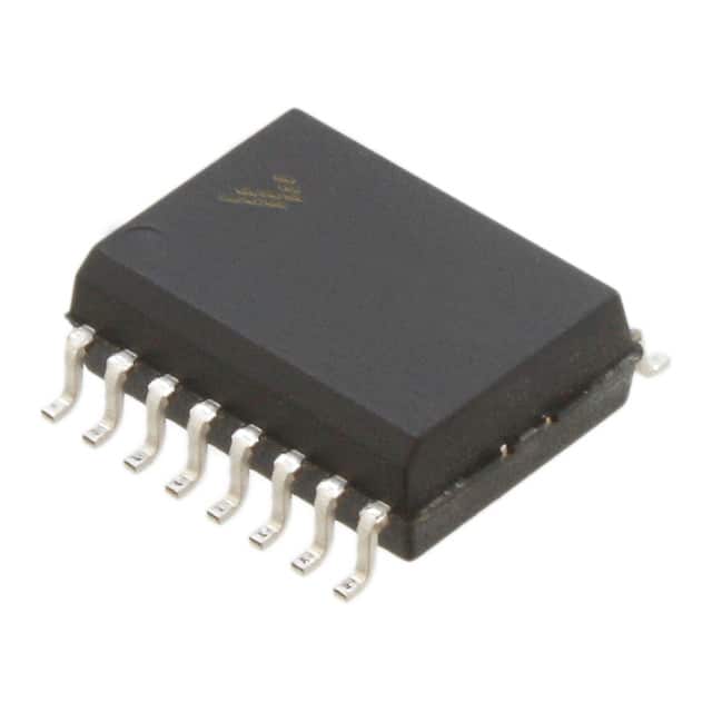
- Part No.:
- MCZ33094EG
- Manufacturer:
- NXP Semiconductors
- Category:
- Specialized
- Package:
- 16-SOIC (0.295", 7.50mm Width)
- Datasheet:
-
 MCZ33094EG.pdf
- Description:
- IC INTERFACE SPECIALIZED 16SOIC
- Quantity:
- Payment:

- Shipping:

Inventory:2,624
Please send an inquiry. Send us your inquiry, and we will respond immediately.
Product details
Overview
MCZ33094EG from NXP Semiconductors (formerly Freescale) is an automotive ignition control IC designed for 12 V engine management systems. It provides adaptive dwell timing, coil current limiting (≈6.5 A), overvoltage shutdown (23.7–31 V), and Hall sensor–driven RPM/position sensing. Used with external Power Darlington transistors, it enables precise spark timing in gasoline engine ignition coils.
For engineers reviewing the MCZ33094EG datasheet, MCZ33094EG pinout, MCZ33094EG application, or MCZ33094EG equivalent, this page delivers verified technical context, validated pin functions, confirmed operating temperature range (−40°C to +125°C), real-world timing behavior (e.g., tSSD = 4.6–8.8 ms stall-to-spark delay), and two documented alternative ignition controllers for direct functional comparison.
Technical Context
The MCZ33094EG implements adaptive dwell control using three external capacitors (CA, CR, CS) to dynamically adjust coil charging time across 1–400 Hz engine speeds. Its IIL bipolar process integrates high-gain PNP/NPN transistors, band-gap reference (1.2 V), and VR zener (6.75 V) for thermal stability.
It features dual-mode operation: start mode forces maximum dwell via adaptive capacitor discharge, while run mode enables adaptive dwell based on ramp capacitor voltage tracking. Stall detection uses CS voltage decay below 1.95–2.45 V to reduce coil current during cranking or low-RPM conditions.
Key Specifications
| Parameter | Value and Actual Design Meaning |
|---|---|
| Supply Voltage Range | 6.0–28.6 V - Supports full automotive battery range including load dump transients up to 28.6 V |
| Operating Temperature | −40°C to +125°C ambient - Qualified for under-hood engine compartment deployment |
| Output Current Drive | 40–65 mA - Sufficient base drive for Freescale Power Darlington transistors (e.g., MJD127) |
| Coil Current Limit | ≈6.5 A - Enforced via Current Sense (S) pin comparator; prevents coil saturation and overheating |
| Overvoltage Shutdown | 23.7–31 V - Disables output above threshold to protect downstream Darlington and coil |
| Stall Detection Threshold | 1.95–2.45 V on CS pin - Triggers controlled coil discharge when engine stalls or cranks slowly |
| Propagation Delay | 0–15 µs - Ensures fast response to distributor signal edges for accurate spark timing |
Pinout & Package
MCZ33094EG is housed in a 16-pin SOICW (wide-body surface-mount) package, Pb-free per EG suffix, rated for −40°C to +125°C ambient operation.
| Pin/Terminal | Circuit Role | Design Meaning |
|---|---|---|
| 1, 5, 16 | NC | No internal connection - Must remain unconnected per datasheet |
| 2 | MB (Master Bias) | Internal bias reference node - Held at 1.12–1.32 V; external resistor sets precision current references |
| 3 | CA (Adaptive Capacitor) | Dwell adaptation timing node - External capacitor programs adaptive charge/discharge rates (ICA1–ICA5) |
| 4 | CR (Ramp Capacitor) | Engine speed–synchronized timing node - Charges at ~8.4 µA; CR/CA ratio determines dwell onset point |
| 6 | GND | IC ground reference - Shared return for all analog and logic circuitry |
| 7 | VIN(−) (Negative Input) | Hall/reluctance sensor interface - Accepts distributor signal; 50–65% VCC positive threshold with negative-edge filtering |
| 8 | ST (Start) | Start/run mode selector - High = start mode (max dwell); low = run mode (adaptive dwell) |
| 9 | VCC | Main supply input - Powers all internal blocks; includes overvoltage clamp and hysteresis (VCC1/VCC2) |
| 10 | D (Distributor Signal) | Battery-side coil voltage monitor - Used for spark timing synchronization and inductive kick detection |
| 11 | CL (Coil) | Coil voltage sense input - Interfaces with external voltage divider to enable dynamic clamp (≤350 V) |
| 12 | O (Output) | Darlington base driver - Delivers 40–65 mA to external transistor; includes clamp protection (13.7–15.58 V) |
| 13 | T (Process Test) | Factory test access - Not intended for end-user circuit connection |
| 14 | S (Current Sense) | Coil current feedback - Monitors emitter voltage of external Darlington to enforce 6.5 A limit |
| 15 | CS (Stall Capacitor) | Stall detection integrator - Charges at 31.5 µA; discharge rate changes based on engine speed to detect stall |
Key Features
| Feature | Design Value |
|---|---|
| Adaptive dwell timing | Automatically adjusts coil charge time across 1–400 Hz engine speeds using CA/CR/CS capacitor network |
| Overvoltage shutdown with auto-recovery | Disables output above 23.7–31 V VCC and resumes operation once voltage falls below hysteresis threshold |
| Integrated band-gap reference | 1.12–1.32 V master bias voltage with <±10 mV drift over −40°C to +125°C for stable current references |
| Negative-edge input filter | ~614 µs falling-edge time constant on VIN(−) to suppress Hall sensor switching transients and prevent false sparks |
| Stall-aware current limiting | Reduces coil current proportionally to CS voltage below 1.95 V, preventing overheating during cranking or stall |
Applications
| Gasoline Engine Ignition Control | Electronic Distributor Replacement |
|---|---|
Use Scenario: Controlling primary current in ignition coils for 4- to 8-cylinder gasoline engines in passenger vehicles and light trucks. IC Role / Device Role / Timing Role: Adaptive dwell controller that synchronizes coil charging with crankshaft position via Hall sensor input and distributor signal edge detection. Use Value: Enables consistent spark energy across 0–7000 RPM while reducing coil power dissipation during high-voltage battery conditions. |
Use Scenario: Replacing mechanical distributors with solid-state timing control in retrofit or OEM engine management systems. IC Role / Device Role / Timing Role: Provides single-ended Hall sensor interface, 25% clock generation, and spark-triggered coil discharge logic. Use Value: Eliminates moving parts and wear-prone contacts while maintaining factory-level spark timing accuracy and EMI robustness. |
| Start-Mode Enhanced Cranking | Low-Speed Stall Mitigation |
Use Scenario: Delivering maximum dwell during engine cranking (<300 RPM) to ensure reliable cold-start spark energy. IC Role / Device Role / Timing Role: Forces adaptive capacitor discharge via ST pin high state, disabling adaptive algorithm and locking dwell at maximum. Use Value: Guarantees ≥6.5 A coil current even at 6 V battery voltage, improving first-fire reliability in sub-zero conditions. |
Use Scenario: Preventing ignition coil overheating and ECU reset during prolonged idling or stalled engine conditions. IC Role / Device Role / Timing Role: Monitors CS capacitor voltage decay to detect low-RPM stall and scales coil current linearly down to zero. Use Value: Limits average coil power to <1.5 W during stall, avoiding thermal shutdown while preserving restart capability. |
Equivalent & Alternatives
The following parts are listed as comparable options for similar ignition control applications.
| Alternative Part | Technical Difference | Application Difference | Selection Advice |
|---|---|---|---|
| MC33095DW | Same architecture but adds integrated Darlington driver (no external transistor required); higher ICC (12–25 mA vs. 5–18 mA) | Reduces BOM count and layout area; less suitable for high-power coils requiring discrete Darlington heat sinking | Select MC33095DW when coil current ≤4 A and board space is constrained; retain MCZ33094EG for >4 A or thermally demanding environments |
| UC2909N | Fixed dwell (non-adaptive); no CA/CR/CS capacitor timing; simpler 8-pin DIP package; no stall detection or overvoltage shutdown | Limited to steady-state RPM operation; requires external overvoltage protection and manual dwell tuning | Choose UC2909N only for legacy 12 V systems with fixed-speed engines and no emission compliance requirements |
Compared with MC33094EG, MC33095DW integrates the Darlington driver but sacrifices thermal headroom and programmability, while UC2909N offers basic functionality at lower cost but lacks adaptive timing, stall handling, and automotive-grade protection - making MCZ33094EG the optimal choice for modern emission-compliant gasoline ignition systems.
Availability
MCZ33094EG is available at Aetrix Electronics and suitable for automotive engine control units, aftermarket ignition modules, and electronic distributor replacements requiring stable component supply across extended temperature ranges and long production lifecycles.
Supply support for MCZ33094EG includes scheduled delivery planning, volume procurement assistance, BOM continuity management, traceable sourcing, and lifecycle availability coordination for OEM customers, industrial embedded developers, connected-device designers, and electronics production programs.
Manufacturer
NXP Semiconductors acquired Freescale in 2015 and maintains full support for legacy automotive analog products. The company specializes in secure, high-reliability silicon for automotive, industrial, and IoT applications.
The MCZ33094EG belongs to Freescale's legacy analog ignition controller family, engineered specifically for robust, adaptive spark timing in 12 V gasoline engine compartments - emphasizing thermal stability, transient immunity, and fail-safe coil current control.
FAQ
What is the function of the MB (Master Bias) pin on the MCZ33094EG?
The MB pin on the MCZ33094EG provides a stabilized 1.12–1.32 V reference voltage used to generate precision internal bias currents. It must be connected to an external resistor to set master bias current; capacitive loading >200 pF risks amplifier oscillation. This pin is critical for maintaining consistent timing and current-limiting accuracy across temperature in the MCZ33094EG.
Does the MCZ33094EG support both Hall effect and variable reluctance sensors?
Yes, the MCZ33094EG supports both sensor types via its VIN(−) input. It accepts differential signals from Hall sensors (with 50–65% VCC positive threshold) and single-ended signals from variable reluctance sensors. The internal negative-edge filter (614 µs time constant) suppresses transients common to both, ensuring reliable spark triggering in noisy engine environments for the MCZ33094EG.
How does the MCZ33094EG implement overvoltage protection?
The MCZ33094EG monitors VCC and triggers shutdown when voltage exceeds 23.7–31 V, clamping output until VCC drops below hysteresis. It also reduces adaptive dwell during high-VCC operation to limit coil power dissipation. This dual-stage protection - hard shutdown plus adaptive mitigation - ensures safe operation during automotive load dump events for the MCZ33094EG.
Can the MCZ33094EG operate without external capacitors CA, CR, and CS?
No. The MCZ33094EG requires all three external capacitors: CA sets adaptive dwell timing, CR governs engine-speed–synchronized ramp timing, and CS enables stall detection. Omitting any disables core functionality - e.g., missing CS prevents stall current reduction, missing CR halts dwell calculation, and missing CA locks dwell at startup value. These are mandatory for correct MCZ33094EG operation.
What is the purpose of the D (Distributor Signal) pin on the MCZ33094EG?
The D pin on the MCZ33094EG monitors the battery-side voltage of the ignition coil to detect inductive kick and synchronize spark timing. It works with internal logic to determine spark command timing and enables dynamic voltage clamping (≤350 V) when used with an external voltage divider and the CL pin. This ensures precise, repeatable spark events in the MCZ33094EG.
MCZ33094EG Specifications
- Product attributes
- Attribute value
- Manufacturer:
- NXP Semiconductors
- Series:
- -
- Package/Case:
- 16-SOIC (0.295", 7.50mm Width)
- Packaging:
- Tube
- Product Status:
- Obsolete
- Applications:
- -
- Interface:
- -
- Voltage - Supply:
- 6V ~ 16V
- Supplier Device Package:
- 16-SOIC
- Grade:
- Automotive
- Qualification:
- -
- Mounting Type:
- Surface Mount
MCZ33094EG FAQ
1.How can I place an order for MCZ33094EG through Aetrix?
Please submit a Request for Quotation (RFQ) for MCZ33094EG on Aetrix. Our sales agent will provide a competitive quotation and guide you through the order confirmation once you accept the terms.
2.Are the price and stock information for MCZ33094EG reliable?
The price and inventory of MCZ33094EG are updated periodically and may fluctuate due to market conditions. Stock and pricing data are typically refreshed every 24 hours. Quotation validity for MCZ33094EG is usually 5 days.
3.What payment methods are accepted for MCZ33094EG?
We accept Wire Transfer, PayPal, Credit Card, Western Union, MoneyGram, and Escrow for MCZ33094EG transactions.
Note: Certain payment methods may incur a processing fee.
4.How is shipping managed for MCZ33094EG?
MCZ33094EG orders can be shipped via leading logistics carriers, including DHL, UPS, FedEx, TNT, or Registered Mail.
Once your MCZ33094EG order is processed, you will receive an email with the shipment details and tracking number.
Note: Tracking information may take up to 24 hours to appear. Express delivery typically takes 3–5 business days.
5.How can I obtain technical support or documentation for MCZ33094EG?
For technical support, including MCZ33094EG datasheets, pinout diagrams, or application guidance, please contact our engineering support team. They can provide detailed documentation and assistance for your MCZ33094EG requirements.
6.How does Aetrix verify that MCZ33094EG is sourced from the original manufacturer or authorized distributors?
All MCZ33094EG products on Aetrix are procured from qualified distributors and authorized channels. Our dedicated quality assurance team conducts strict verification, including traceability checks and, if necessary, third-party testing. This ensures that MCZ33094EG meets industry standards.
7.What is the process for return or replacement of MCZ33094EG?
All MCZ33094EG units undergo pre-shipment inspection (PSI). If there is an issue with MCZ33094EG, returns or replacements are accepted under the following conditions:
1.Quantity discrepancies, incorrect items, or visible external defects (such as breakage or corrosion), acknowledged by Aetrix.
2.The issue is reported within 90 days of delivery.
3.The MCZ33094EG part is unused and in its original packaging.
Return procedure for MCZ33094EG:
1.Submit a request within 90 days.
2.Obtain a Return Material Authorization (RMA) from Aetrix.
MCZ33094EG Tags

-
NVT4857UKAZ
NXP Semiconductors

-
TCA8418RTWR
Texas Instruments

-
PCA9546APWR
Texas Instruments

-
MD0100N8-G
Microchip Technology

-
PCA9548APW,118
NXP Semiconductors

-
PCA9540BDP,118
NXP Semiconductors

-
PCA9548APWR
Texas Instruments

-
PCA9546APW,118
NXP Semiconductors

-
PTN3360DBS,518
NXP Semiconductors

-
PCA9546ABS,118
NXP Semiconductors

-
PCA9518PWR
Texas Instruments

-
PCA9545APW,118
NXP Semiconductors
Tech Hub

A practical engineering guide to 3.3V and 5V logic compatibility, input thresholds, resistor dividers, translator ICs, MOSFET level shifting, I2C pull-ups, timing limits and power-sequencing risks.

The 74HC595 uses push-pull logic outputs, while the TPIC6B595 uses 50 V open-drain DMOS sinks for higher-power loads. This guide compares timing, current limits, 3.3 V interfacing, load wiring, thermal…

The 74HC595 converts serial data into eight stable parallel outputs. This guide covers pin functions, shift and storage timing, OE and MR behavior, drive-current limits, cascading, voltage compatibilit…

A technical comparison of level-sensitive latches and edge-triggered flip-flops, covering timing windows, setup and hold limits, master–slave operation, time borrowing, race-through, HDL inference and…

A D latch stores one bit while Enable controls when data can pass. This reference covers gate-level operation, truth tables, transparency, setup and hold timing, LE versus OE, common ICs and practical …

An SR latch stores one bit through cross-coupled feedback. This engineering reference covers NOR and NAND implementations, truth tables, forbidden-state recovery, gated operation, switch debouncing, fa…

Latch circuits retain one bit through feedback. This technical reference covers SR and D latches, truth tables, transparency, timing limits, latch-versus-flip-flop behavior, applications and common log…

An engineering guide to LED driver operation, constant-current and constant-voltage outputs, linear and switching topologies, dimming, IC selection, calculations, replacement compatibility, and fault c…

Operational amplifier guide covering op amp basics, feedback, ideal vs real op amps, common configurations, buffer circuits, offset, bias current, gain-bandwidth, slew rate, rail-to-rail limits and sel…

Jumper cables guide covering safe connection order, red and black clamp placement, final ground connection, cable gauge, length, clamp quality, copper vs CCA cables, jump starter comparison and battery…


