
 My Inquiry
 My Account


NXP Semiconductors MCZ33780EG
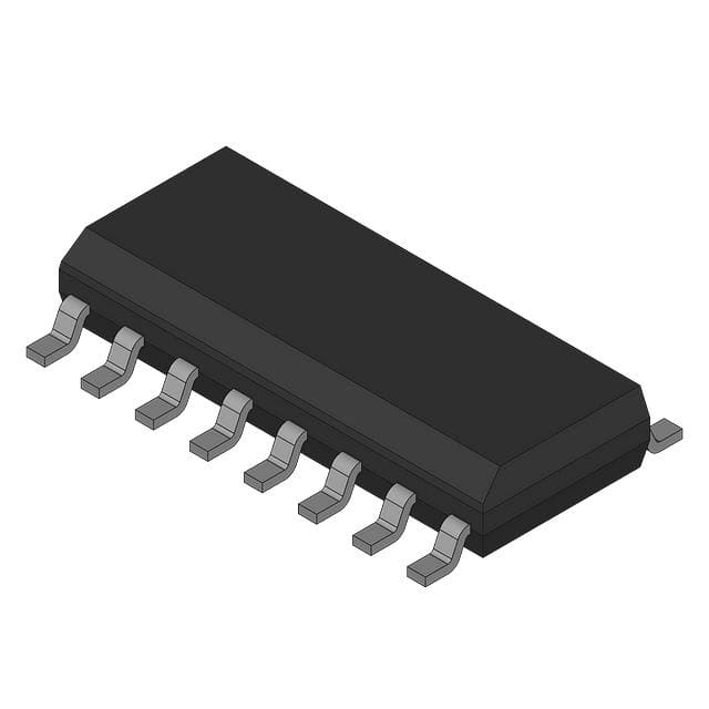
- Part No.:
- MCZ33780EG
- Manufacturer:
- NXP Semiconductors
- Category:
- Specialized
- Package:
- 16-SOIC (0.295", 7.50mm Width)
- Datasheet:
-
 MCZ33780EG.pdf
- Description:
- TRANSCEIVER, DSI, DIFFERENTIAL,
- Quantity:
- Payment:

- Shipping:

Inventory:1,072
Please send an inquiry. Send us your inquiry, and we will respond immediately.
Product details
Overview
MCZ33780EG from NXP Semiconductors (formerly Freescale) is a dual-channel differential DBUS master IC with integrated SPI interface, differential bus drivers/receivers, and frequency spreading for EMI reduction. It operates across -40°C to +85°C, supports up to 150 kbps data rate, delivers ±200 mA bus drive capability per channel, and uses a 4.0 MHz external clock. It enables robust communication in automotive body electronics and distributed control systems where noise immunity and power-over-bus are required.
For engineers reviewing the MCZ33780EG datasheet, MCZ33780EG pinout, MCZ33780EG application, or MCZ33780EG equivalent, this device is selected for its dual independent DBUS channels, automatic CRC generation/checking, open-drain interrupt output with maskable send/receive status, four-stage FIFO buffering, and Pb-free 16-pin SOICW packaging - all critical for deterministic timing, fault-tolerant bus architectures, and automotive-grade supply stability.
Technical Context
The MCZ33780EG implements two fully independent DBUS physical layers, each with dedicated driver/receiver circuitry, spread-spectrum modulation, and protocol engine logic. Its dual-channel architecture allows simultaneous operation on Bus 0 (D0H/D0L) and Bus 1 (D1H/D1L), with separate frequency spreading control per channel and independent transmit/receive FIFOs.
It interfaces exclusively via SPI (CS, SCLK, MOSI, MISO, RST), requires an external 4.0 MHz clock on CLK, and uses VSUP (9–25 V) for bus power delivery while VCC (4.75–5.25 V) powers digital logic. The analog front-end includes slew-rate-controlled drivers, overcurrent shutdown (±30 mA trip), thermal shutdown (155–190°C), and common-mode correction to maintain <0.3 Vpp VCM during transitions.
Key Specifications
| Parameter | Value and Actual Design Meaning |
|---|---|
| Data Rate | Up to 150 kbps - ensures real-time response in distributed sensor/actuator networks without violating ISO 11898-like timing constraints. |
| Bus Voltage Range | VSUP = 9.0–25 V - supports wide automotive battery range including load-dump conditions up to 40 V transient. |
| Differential Output Swing | VDnD(HIGH) = 4.175–4.825 V; VDnD(LOW) = 1.175–1.825 V - provides >3 V differential margin for reliable noise immunity in harsh environments. |
| Slew Rate | Signal mode: 3.0–8.0 V/µs; Idle-to-signal: 2.0–8.0 V/µs - balances EMI suppression with signal integrity across varying cable capacitance. |
| CRC Support | 8- to 16-bit messages with 0- to 8-bit CRC - enables end-to-end data integrity verification for safety-critical bus transactions. |
| Thermal Protection | Thermal shutdown at 155–190°C - prevents latch-up or permanent damage during sustained overcurrent or ambient overheating. |
| ESD Robustness | HBM ±2000 V, MM ±200 V - meets automotive component-level ESD requirements per ISO 10605. |
Pinout & Package
MCZ33780EG is housed in a 16-pin SOICW (Small Outline Integrated Circuit, Wide-body) package with 1.27 mm pitch, RoHS-compliant and Pb-free (suffix EG). Pin 1 is marked with a notch or dot; pins are numbered counter-clockwise starting from top-left corner when viewed from top with marking side up.
| Pin/Terminal | Circuit Role | Design Meaning |
|---|---|---|
| RST | Asynchronous reset input | Active-low signal that forces all registers to known state; internal pulldown current of 4–10 µA ensures defined startup. |
| CS | SPI chip select | Low-active enable for SPI transactions; high-impedance MISO when CS is high. |
| INT | Open-drain interrupt output | Pullup current of -50 to -100 µA enables wired-OR with other interrupt sources; asserts low on FIFO events. |
| MOSI | SPI data input | Samples on rising edge of SCLK; input hysteresis ≥500 mV rejects noise on shared MCU bus lines. |
| SCLK | SPI clock input | Drives internal SPI logic; timing requires tCYC ≥200 ns, tHI/tLO ≥80 ns for reliable byte transfers. |
| MISO | SPI data output | Changes on falling edge of SCLK; VOH ≥ VCC−0.8 V ensures clean logic-high level into MCU input. |
| CLK | System clock input | 4.0 MHz external crystal or oscillator required; no internal PLL - eliminates jitter-sensitive clock synthesis. |
| GND (Pins 8,10,16) | Analog/digital/power ground | Three separate GND pins isolate logic, Bus 0 return, and Bus 1 return to minimize ground bounce coupling. |
| VCC | Digital supply | +5.0 V nominal logic supply; IVCC = 4.5–6.0 mA typical - compatible with standard MCU LDO rails. |
| VSUP | Bus power supply | +9–25 V input powering slave devices; supplies idle bus voltage and drives D0H/D0L/D1H/D1L outputs. |
| D0L / D0H | Bus 0 differential outputs | Low-side and high-side drivers for Channel 0; each rated for ±400 mA peak current with overcurrent shutdown. |
| D1L / D1H | Bus 1 differential outputs | Independent low/high-side drivers for Channel 1; identical specs to D0L/D0H - enables true dual-bus redundancy. |
Key Features
| Feature | Design Value |
|---|---|
| Dual independent DBUS I/O channels | Enables concurrent communication with two physically separate bus segments - ideal for multi-zone vehicle body control (e.g., front/rear lighting clusters). |
| Frequency spreading per channel | Reduces peak EMI by ±400–1100 ns bit deviation at 132–148 kHz center frequency - meets CISPR 25 Class 3 radiated emissions limits without shielding. |
| Automatic CRC generation & checking | Offloads MCU firmware from bit-level error detection; supports configurable CRC length (0–8 bits) aligned with message payload size. |
| Four-stage TX/RX FIFO buffers | Allows burst SPI reads/writes without real-time bus arbitration; prevents data loss during MCU interrupt latency or scheduling gaps. |
| Open-drain INT with pullup current | Supports multi-master interrupt aggregation; -50 to -100 µA pullup ensures fast rise time even with 10 kΩ external pullup. |
| Bus idle voltage regulation | Maintains VDnD(IDLE) = VSUP − 2.5 V - charges slave storage capacitors to sustain operation during bus quiescence. |
Applications
| Automotive Body Control Module (BCM) | Industrial Distributed I/O Network |
|---|---|
Use Scenario: Centralized control of door locks, interior lighting, mirror adjustment, and seat position sensors across multiple vehicle zones. IC Role / Device Role / Timing Role: Dual-channel DBUS master coordinating up to 30 slave nodes (15 per bus) with deterministic 150 kbps messaging and CRC-protected commands. Use Value: Eliminates CAN wiring complexity while delivering comparable noise immunity and power-over-bus - reduces harness weight and connector count by 40% vs. discrete wiring. | Use Scenario: Factory floor machine monitoring using daisy-chained sensors (temperature, pressure, proximity) connected over long twisted-pair runs. IC Role / Device Role / Timing Role: Robust physical layer controller enabling >100 m bus length at 150 kbps with built-in slew-rate control and common-mode correction. Use Value: Tolerates 4.7 nF bus-to-ground capacitance per line without signal degradation - supports legacy cabling infrastructure without re-engineering. |
| Smart Lighting System Controller | Automotive Load Dump Protected Node |
Use Scenario: Adaptive headlamp control unit managing LED drivers, ambient light sensors, and camera-based glare detection modules. IC Role / Device Role / Timing Role: Dual-bus master providing isolated communication paths: one for safety-critical lamp status reporting, another for non-critical calibration data. Use Value: Independent frequency spreading per channel prevents cross-talk between safety and diagnostic traffic - satisfies ASIL-B functional safety partitioning. | Use Scenario: Under-hood module exposed to 40 V load-dump transients during alternator regulation faults. IC Role / Device Role / Timing Role: DBUS master with VSUP-rated inputs (−0.3 to 26.5 V) and thermal shutdown (155–190°C) ensuring continued operation during extreme electrical stress. Use Value: Withstands 300 ms 40 V transients without latch-up or parameter shift - eliminates need for external TVS diodes on VSUP rail. |
Equivalent & Alternatives
The following parts are listed as comparable options for similar differential bus master applications.
| Alternative Part | Technical Difference | Application Difference | Selection Advice |
|---|---|---|---|
| MC33793 | Single-channel DBUS slave IC; lacks SPI interface, frequency spreading, and master protocol engine - requires external MCU for bus arbitration. | Used only as endpoint node; cannot replace MCZ33780EG as system master or dual-bus coordinator. | Select MC33793 only for adding slave functionality to existing MCZ33780EG-based networks - not a functional substitute. |
| NCP1034 | Single-channel LIN transceiver with 12 V supply; no frequency spreading, no CRC, no dual-bus capability; max data rate 20 kbps. | Designed for low-speed automotive sub-networks (e.g., HVAC controls); incompatible with DBUS protocol stack or power-over-bus requirements. | Choose NCP1034 only for cost-sensitive, non-power-delivering LIN applications - not suitable for DBUS migration or performance parity. |
Compared with MC33780EG, MC33793 serves only as a slave endpoint requiring external master coordination, while NCP1034 offers lower integration, no frequency spreading, and insufficient data rate or bus power capability - neither provides dual-channel DBUS master functionality with EMI-reducing spread spectrum or autonomous CRC handling.
Availability
MCZ33780EG is available at Aetrix Electronics and suitable for automotive body electronics, industrial distributed I/O systems, smart lighting controllers, and load-dump protected node designs requiring stable component supply, long-term lifecycle support, and AEC-Q100-compliant sourcing.
Supply support for MCZ33780EG includes scheduled delivery planning, volume procurement assistance, BOM continuity management, traceable sourcing, and lifecycle availability coordination for OEM customers, industrial embedded developers, connected-device designers, and electronics production programs.
Manufacturer
NXP Semiconductors is a global semiconductor leader focused on secure connectivity solutions for automotive, industrial, and IoT applications, with deep heritage in automotive analog and mixed-signal ICs.
The MCZ33780EG belongs to NXP's legacy DBUS product line, designed specifically for noise-immune, power-over-bus distributed control in automotive body electronics - emphasizing EMI resilience, dual-channel independence, and deterministic timing under voltage transients.
FAQ
What is the primary function of the MCZ33780EG in a distributed control system?
The MCZ33780EG acts as a dual-channel differential DBUS master IC, interfacing a microcontroller via SPI to manage two independent DBUS networks. It handles physical layer signaling (differential drive/receive), protocol timing, automatic CRC generation/checking, and frequency spreading for EMI reduction - enabling robust, power-over-bus communication with up to 15 slaves per channel without requiring additional bus arbitration logic. Its design centers on deterministic timing and noise immunity in automotive and industrial settings.
Does the MCZ33780EG require an external clock source, and what are its timing requirements?
Yes, the MCZ33780EG requires an external 4.0 MHz clock applied to the CLK pin - it contains no internal oscillator or PLL. This clock drives all internal timing, including SPI interface synchronization, DBUS bit timing, and spread-spectrum modulation. The clock must meet strict stability and jitter specifications; deviations outside ±1% may cause CRC errors or bus timing violations. The device does not support clock scaling or frequency division internally.
How does the MCZ33780EG handle electromagnetic interference (EMI) in automotive environments?
The MCZ33780EG reduces EMI through two integrated mechanisms: differential signaling (lower common-mode radiation than single-ended buses) and per-channel frequency spreading (±400–1100 ns bit deviation at 132–148 kHz center frequency). Together, these features suppress narrowband spectral peaks, helping systems meet CISPR 25 Class 3 radiated emissions limits without added shielding or ferrites - a key advantage in space-constrained automotive modules.
What are the voltage and current ratings for the VSUP and bus driver pins of the MCZ33780EG?
The VSUP pin accepts 9.0–25 V DC with transient rating up to 40 V for 300 ms (load dump). Bus driver outputs (D0H/D0L/D1H/D1L) deliver differential voltages of 4.175–4.825 V (HIGH) and 1.175–1.825 V (LOW), with ±400 mA peak current capability and overcurrent shutdown triggered at ±30 mA. Idle-mode bus voltage is regulated to VSUP − 2.5 V to charge slave storage capacitors.
Can the MCZ33780EG operate with only one DBUS channel enabled, and how is channel selection managed?
Yes, the MCZ33780EG supports independent enable/disable of each DBUS channel via configuration registers accessible through its SPI interface. Channel-specific control bits in the D0CTRL and D1CTRL registers allow disabling unused channels to reduce power consumption (IVSUP drops from 10–23 mA to ~6.5 mA in idle HiZ mode) and eliminate unnecessary EMI. No hardware modification is needed - full channel control is software-configurable at runtime.
MCZ33780EG Specifications
- Product attributes
- Attribute value
- Manufacturer:
- NXP Semiconductors
- Series:
- -
- Package/Case:
- 16-SOIC (0.295", 7.50mm Width)
- Packaging:
- Bulk
- Product Status:
- Obsolete
- Applications:
- -
- Interface:
- -
- Voltage - Supply:
- -
- Supplier Device Package:
- 16-SOIC
- Grade:
- -
- Qualification:
- -
- Mounting Type:
- Surface Mount
MCZ33780EG FAQ
1.How can I place an order for MCZ33780EG through Aetrix?
Please submit a Request for Quotation (RFQ) for MCZ33780EG on Aetrix. Our sales agent will provide a competitive quotation and guide you through the order confirmation once you accept the terms.
2.Are the price and stock information for MCZ33780EG reliable?
The price and inventory of MCZ33780EG are updated periodically and may fluctuate due to market conditions. Stock and pricing data are typically refreshed every 24 hours. Quotation validity for MCZ33780EG is usually 5 days.
3.What payment methods are accepted for MCZ33780EG?
We accept Wire Transfer, PayPal, Credit Card, Western Union, MoneyGram, and Escrow for MCZ33780EG transactions.
Note: Certain payment methods may incur a processing fee.
4.How is shipping managed for MCZ33780EG?
MCZ33780EG orders can be shipped via leading logistics carriers, including DHL, UPS, FedEx, TNT, or Registered Mail.
Once your MCZ33780EG order is processed, you will receive an email with the shipment details and tracking number.
Note: Tracking information may take up to 24 hours to appear. Express delivery typically takes 3–5 business days.
5.How can I obtain technical support or documentation for MCZ33780EG?
For technical support, including MCZ33780EG datasheets, pinout diagrams, or application guidance, please contact our engineering support team. They can provide detailed documentation and assistance for your MCZ33780EG requirements.
6.How does Aetrix verify that MCZ33780EG is sourced from the original manufacturer or authorized distributors?
All MCZ33780EG products on Aetrix are procured from qualified distributors and authorized channels. Our dedicated quality assurance team conducts strict verification, including traceability checks and, if necessary, third-party testing. This ensures that MCZ33780EG meets industry standards.
7.What is the process for return or replacement of MCZ33780EG?
All MCZ33780EG units undergo pre-shipment inspection (PSI). If there is an issue with MCZ33780EG, returns or replacements are accepted under the following conditions:
1.Quantity discrepancies, incorrect items, or visible external defects (such as breakage or corrosion), acknowledged by Aetrix.
2.The issue is reported within 90 days of delivery.
3.The MCZ33780EG part is unused and in its original packaging.
Return procedure for MCZ33780EG:
1.Submit a request within 90 days.
2.Obtain a Return Material Authorization (RMA) from Aetrix.
MCZ33780EG Tags

-
NVT4857UKAZ
NXP Semiconductors

-
TCA8418RTWR
Texas Instruments

-
PCA9546APWR
Texas Instruments

-
MD0100N8-G
Microchip Technology

-
PCA9548APW,118
NXP Semiconductors

-
PCA9540BDP,118
NXP Semiconductors

-
PCA9548APWR
Texas Instruments

-
PCA9546APW,118
NXP Semiconductors

-
PTN3360DBS,518
NXP Semiconductors

-
PCA9546ABS,118
NXP Semiconductors

-
PCA9518PWR
Texas Instruments

-
PCA9545APW,118
NXP Semiconductors
Tech Hub

A practical engineering guide to 3.3V and 5V logic compatibility, input thresholds, resistor dividers, translator ICs, MOSFET level shifting, I2C pull-ups, timing limits and power-sequencing risks.

The 74HC595 uses push-pull logic outputs, while the TPIC6B595 uses 50 V open-drain DMOS sinks for higher-power loads. This guide compares timing, current limits, 3.3 V interfacing, load wiring, thermal…

The 74HC595 converts serial data into eight stable parallel outputs. This guide covers pin functions, shift and storage timing, OE and MR behavior, drive-current limits, cascading, voltage compatibilit…

A technical comparison of level-sensitive latches and edge-triggered flip-flops, covering timing windows, setup and hold limits, master–slave operation, time borrowing, race-through, HDL inference and…

A D latch stores one bit while Enable controls when data can pass. This reference covers gate-level operation, truth tables, transparency, setup and hold timing, LE versus OE, common ICs and practical …

An SR latch stores one bit through cross-coupled feedback. This engineering reference covers NOR and NAND implementations, truth tables, forbidden-state recovery, gated operation, switch debouncing, fa…

Latch circuits retain one bit through feedback. This technical reference covers SR and D latches, truth tables, transparency, timing limits, latch-versus-flip-flop behavior, applications and common log…

An engineering guide to LED driver operation, constant-current and constant-voltage outputs, linear and switching topologies, dimming, IC selection, calculations, replacement compatibility, and fault c…

Operational amplifier guide covering op amp basics, feedback, ideal vs real op amps, common configurations, buffer circuits, offset, bias current, gain-bandwidth, slew rate, rail-to-rail limits and sel…

Jumper cables guide covering safe connection order, red and black clamp placement, final ground connection, cable gauge, length, clamp quality, copper vs CCA cables, jump starter comparison and battery…


