
 My Inquiry
 My Account


NXP Semiconductors MCZ33780EGR2
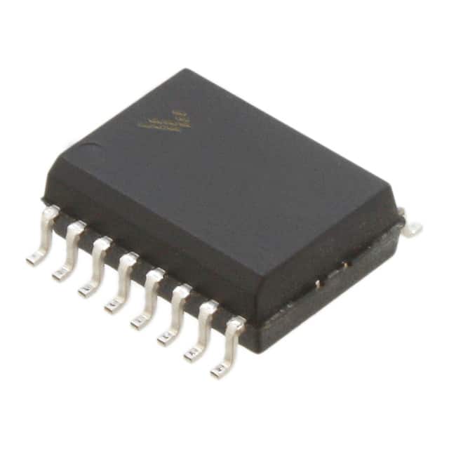
- Part No.:
- MCZ33780EGR2
- Manufacturer:
- NXP Semiconductors
- Category:
- Specialized
- Package:
- 16-SOIC (0.295", 7.50mm Width)
- Datasheet:
-
 MCZ33780EGR2.pdf
- Description:
- IC INTERFACE SPECIALIZED 16SOIC
- Quantity:
- Payment:

- Shipping:

Inventory:1,697
Please send an inquiry. Send us your inquiry, and we will respond immediately.
Product details
Overview
MCZ33780EGR2 from NXP (formerly Freescale) is a dual-channel differential DBUS master IC for automotive and industrial distributed bus systems. It interfaces two independent DBUS channels to an MCU via SPI, provides differential drive with 4.5 V differential signal swing, supports up to 150 kbps data rate, features independent frequency spreading per channel, and operates from -40°C to +85°C in 16-pin SOICW package.
For engineers reviewing the MCZ33780EGR2 datasheet, MCZ33780EGR2 pinout, MCZ33780EGR2 application, or MCZ33780EGR2 equivalent, this page delivers verified electrical specs, SPI timing constraints, DBUS driver/receiver behavior, thermal shutdown thresholds, and real-world design implications of its dual-bus architecture and spread-spectrum EMI reduction.
Technical Context
The MCZ33780EGR2 implements a dual-channel DBUS physical layer with separate idle and signal drivers per bus, enabling simultaneous power delivery and data transmission over twisted-pair wiring. Its protocol engine handles CRC generation/checking for 8–16-bit messages and manages four-stage transmit/receive FIFOs with maskable interrupts on TX-empty and RX-not-empty events.
Each channel uses independent spread-spectrum modulation (132–148 kHz center frequency) to reduce peak EMI emissions, while analog receiver circuitry includes a 2.0 pF filter capacitor and 6 mA comparator trip point for robust slave response detection. The device requires external 4.7 nF capacitors from DnH/DnL to ground for stable common-mode control and slew-rate management.
Key Specifications
| Parameter | Value and Actual Design Meaning |
|---|---|
| Data Rate | Up to 150 kbps - defines maximum message throughput per DBUS channel under specified load and slew conditions. |
| Differential Output Swing | 4.5 V (typ) - ensures sufficient noise margin for reliable communication across noisy automotive harnesses. |
| VSUP Supply Range | 9.0 V to 25 V - powers remote DBUS slaves during idle; supports load-dump transients up to 40 V (300 ms). |
| SPI Clock Period | 245 ns min (4.08 MHz max) - constrains MCU SPI peripheral configuration for guaranteed register access timing. |
| Thermal Shutdown | 155–190°C - protects against latch-up or permanent damage during sustained overtemperature operation. |
| Bus Idle Voltage | VSUP − 2.5 V - establishes DC bias level for slave capacitor charging and sets common-mode reference midpoint. |
| Receiver Trip Point | 6.0 mA (typ) - determines minimum detectable slave response current; critical for fault-tolerant bus arbitration. |
| CLK Input Frequency | 4.0 MHz - fixed clock source for internal logic timing; must be externally supplied with low jitter. |
Pinout & Package
MCZ33780EGR2 is housed in a 16-pin Small Outline Integrated Circuit Wide-body (SOICW) package, RoHS-compliant and Pb-free (suffix EG). Pin spacing is 1.27 mm, body width is 7.5 mm, and thermal resistance is RΘJA = 109°C/W.
| Pin | Circuit Role | Design Meaning |
|---|---|---|
| 1 (RST) | IC Reset | Active-low synchronous reset that clears all registers to known state; requires ≥100 ns pulse width. |
| 2 (CS) | SPI Chip Select | Enables SPI transaction when pulled low; ignored when high; signals completion on rising edge. |
| 3 (INT) | Open-Drain Interrupt | Asserts low on enabled TX-empty or RX-not-empty events; internal pull-up (~75 µA at VCC−1V) enables wired-OR sharing. |
| 4 (MOSI) | SPI Data Input | Samples data on SCLK rising edge; accepts register writes and command sequences from MCU. |
| 5 (SCLK) | SPI Clock Input | Drives internal SPI logic; data changes on falling edge (MISO), sampled on rising edge (MOSI). |
| 6 (MISO) | SPI Data Output | Drives register reads and status responses; high-impedance when CS is high. |
| 7 (CLK) | System Clock Input | 4.0 MHz external crystal or oscillator input; not derived from SPI clock; critical for DBUS timing accuracy. |
| 8, 10, 16 (GND) | Ground Reference | Three dedicated GND pins: digital/analog reference (pin 8), Bus 1 return (pin 10), Bus 0 return (pin 16). |
| 9 (VCC) | Logic Supply | +5.0 V ±5% supply for digital core; bypass with 0.01–0.1 µF capacitor close to pin. |
| 11 (D1L) | Bus 1 Low-Side Driver | Differential output for DBUS Channel 1; sinks current during signaling; requires 4.7 nF to GND. |
| 12 (D1H) | Bus 1 High-Side Driver | Differential output for DBUS Channel 1; sources current during signaling; requires 4.7 nF to GND. |
| 13 (VSUP) | Bus Power Supply | +9–25 V input powering slave devices; withstands 40 V load dump; connects to bulk storage capacitor. |
| 14 (D0H) | Bus 0 High-Side Driver | Differential output for DBUS Channel 0; identical function to D1H but electrically isolated channel. |
| 15 (D0L) | Bus 0 Low-Side Driver | Differential output for DBUS Channel 0; identical function to D1L but electrically isolated channel. |
Key Features
| Feature | Design Value |
|---|---|
| Dual Independent DBUS I/O Channels | Enables concurrent control of two physically separate bus segments-e.g., front and rear vehicle domains-without MCU resource contention. |
| Automatic CRC Generation/Checking | Hardware-accelerated 0–8-bit CRC per message eliminates software overhead and guarantees data integrity in electrically noisy environments. |
| Independent Frequency Spreading per Channel | Reduces radiated EMI peaks by spreading energy across 132–148 kHz band-critical for automotive EMC compliance without external filtering. |
| Four-Stage Transmit/Receive Buffers | Supports burst messaging and pipelined operation; prevents data loss during high-latency MCU SPI access or interrupt latency. |
| Open-Drain Maskable INT Output | Allows multiple MCZ33780EGR2 devices or other open-drain peripherals to share single MCU interrupt line with priority-based servicing. |
| Differential Drive with Slew Control | Programmable slew rates (2.0–8.0 V/µs) balance EMI suppression and signal integrity across varying cable lengths and terminations. |
Applications
| Automotive Body Control Module | Industrial Sensor Network Hub |
|---|---|
|
Use Scenario: Centralized control of door locks, window lifts, mirror actuators, and interior lighting across multiple vehicle zones. IC Role / Device Role / Timing Role: Dual-channel DBUS master coordinating up to 30 slave nodes (15 per bus) using differential signaling over long chassis wiring. Use Value: Eliminates point-to-point wiring complexity; enables hot-plug slave detection; maintains operation during open-circuit faults via loop-back topology. |
Use Scenario: Aggregating temperature, pressure, and proximity sensor data from distributed field nodes in factory automation systems. IC Role / Device Role / Timing Role: Robust physical-layer interface converting SPI commands into differential DBUS frames with CRC validation and spread-spectrum EMI mitigation. Use Value: Ensures reliable communication in electrically noisy plant environments where standard UART/RS-485 would require shielding or repeaters. |
| Heavy-Duty Vehicle Telematics Gateway | Off-Road Equipment Diagnostic Interface |
|
Use Scenario: Integrating J1939-compatible ECUs with legacy DBUS-based subsystems (e.g., cab climate, trailer brakes) in trucks and buses. IC Role / Device Role / Timing Role: Protocol bridge translating SPI-based host commands into DBUS physical layer signals with configurable bit timing and voltage levels. Use Value: Enables backward compatibility without redesigning slave modules; supports VSUP up to 25 V for 24 V vehicle systems. |
Use Scenario: Field-service diagnostic tool connecting to DBUS-enabled hydraulic controllers, GPS receivers, and CAN gateways in agricultural machinery. IC Role / Device Role / Timing Role: Portable DBUS master providing real-time bus monitoring, firmware updates, and fault injection via SPI-connected microcontroller. Use Value: Simplifies service workflow with single-cable connection; leverages built-in thermal shutdown and overcurrent protection for rugged handheld use. |
Equivalent & Alternatives
The following parts are listed as comparable options for similar differential bus master applications.
| Alternative Part | Technical Difference | Application Difference | Selection Advice |
|---|---|---|---|
| MC33780EG/R2 | Same silicon die and pinout; differs only in RoHS compliance marking (no Pb-free suffix 'Z'); identical electrical specs and thermal behavior. | No functional difference; used interchangeably where Pb-free certification is not required by end-customer. | Select MCZ33780EGR2 for RoHS-compliant designs; MC33780EG/R2 where legacy compliance suffices and cost sensitivity applies. |
| MC33793EKR2 | Single-channel DBUS slave IC (not master); lacks SPI interface, CRC engine, and dual-bus drivers; designed for endpoint node use only. | Cannot replace MCZ33780EGR2 as master; suitable only as downstream device on same DBUS segment. | Use MC33793EKR2 only as companion slave-not as alternative master; pairing enables full DBUS network topology. |
Compared with MC33780EG/R2, MCZ33780EGR2 adds mandatory Pb-free compliance for global automotive programs, while MC33793EKR2 serves a fundamentally different role as a slave-only device-making it complementary rather than substitutable in master-node designs.
Availability
MCZ33780EGR2 is available at Aetrix Electronics and suitable for automotive body electronics, industrial sensor hubs, and off-road equipment diagnostics requiring stable component supply, long-term lifecycle support, and traceable sourcing.
Supply support for MCZ33780EGR2 includes scheduled delivery planning, volume procurement assistance, BOM continuity management, traceable sourcing, and lifecycle availability coordination for OEM customers, industrial embedded developers, connected-device designers, and electronics production programs.
Manufacturer
NXP Semiconductors is a global semiconductor leader focused on secure connectivity solutions for automotive, industrial, and IoT applications, with deep heritage in automotive analog and mixed-signal ICs.
The MCZ33780EGR2 belongs to NXP's legacy DBUS product line, engineered specifically for robust, low-EMI distributed control in harsh automotive environments-emphasizing fault tolerance, power-over-bus capability, and SPI simplicity.
FAQ
What is the primary function of the MCZ33780EGR2 in a distributed system?
The MCZ33780EGR2 acts as a dual-channel differential DBUS master IC, enabling an MCU to communicate with up to 30 remote slave devices (15 per bus) over twisted-pair wiring. It handles both physical layer signaling-including differential drive, slew control, and power delivery-and protocol-level functions like CRC generation, message buffering, and interrupt management-all via a standard SPI interface. Its design targets automotive and industrial applications where EMI resilience and wiring simplicity are critical.
Does the MCZ33780EGR2 support both 12 V and 24 V vehicle electrical systems?
Yes, the MCZ33780EGR2 supports VSUP input from 9.0 V to 25 V, making it compatible with both 12 V and 24 V automotive platforms. Its absolute maximum rating for load-dump transients is 40 V for 300 ms, satisfying ISO 7637-2 Pulse 5a requirements. The device maintains full functionality-including differential output swing and bus idle voltage-across this entire range, with no configuration changes needed between voltage classes.
How does the spread-spectrum feature of the MCZ33780EGR2 reduce electromagnetic interference?
The MCZ33780EGR2 implements independent frequency spreading per DBUS channel, modulating the bit period around a programmable center frequency (132–148 kHz) with ±400–1100 ns deviation. This spreads spectral energy across a wider bandwidth, reducing peak amplitude at any single frequency-lowering radiated EMI by up to 10 dB compared to fixed-frequency operation. It achieves this without altering data integrity, CRC, or timing margins, and requires no external components.
What external components are mandatory for stable operation of the MCZ33780EGR2?
Four 4.7 nF capacitors-one each from D0H, D0L, D1H, and D1L to ground-are mandatory for proper common-mode control and slew-rate stability. A 0.01–0.1 µF ceramic capacitor must be placed close to the VCC pin for logic supply decoupling. Additionally, a bulk capacitor (≥10 µF) is required on the VSUP rail to sustain slave power during bus idle periods. Missing any of these compromises EMI performance, signal integrity, or thermal reliability.
Can the MCZ33780EGR2 operate without an external 4.0 MHz clock source?
No-the MCZ33780EGR2 requires an external 4.0 MHz clock applied to the CLK pin for all internal timing, including DBUS bit generation, CRC calculation, and SPI synchronization. This clock is not derived from the SPI clock and cannot be omitted or substituted with a lower-frequency oscillator. Deviations beyond ±1% may cause timing violations in DBUS frame generation or receiver sampling, leading to communication errors or missed interrupts.
MCZ33780EGR2 Specifications
- Product attributes
- Attribute value
- Manufacturer:
- NXP Semiconductors
- Series:
- -
- Package/Case:
- 16-SOIC (0.295", 7.50mm Width)
- Packaging:
- Tape & Reel (TR)
- Product Status:
- Not For New Designs
- Applications:
- -
- Interface:
- SPI
- Voltage - Supply:
- -
- Supplier Device Package:
- 16-SOIC
- Grade:
- -
- Qualification:
- -
- Mounting Type:
- Surface Mount
MCZ33780EGR2 FAQ
1.How can I place an order for MCZ33780EGR2 through Aetrix?
Please submit a Request for Quotation (RFQ) for MCZ33780EGR2 on Aetrix. Our sales agent will provide a competitive quotation and guide you through the order confirmation once you accept the terms.
2.Are the price and stock information for MCZ33780EGR2 reliable?
The price and inventory of MCZ33780EGR2 are updated periodically and may fluctuate due to market conditions. Stock and pricing data are typically refreshed every 24 hours. Quotation validity for MCZ33780EGR2 is usually 5 days.
3.What payment methods are accepted for MCZ33780EGR2?
We accept Wire Transfer, PayPal, Credit Card, Western Union, MoneyGram, and Escrow for MCZ33780EGR2 transactions.
Note: Certain payment methods may incur a processing fee.
4.How is shipping managed for MCZ33780EGR2?
MCZ33780EGR2 orders can be shipped via leading logistics carriers, including DHL, UPS, FedEx, TNT, or Registered Mail.
Once your MCZ33780EGR2 order is processed, you will receive an email with the shipment details and tracking number.
Note: Tracking information may take up to 24 hours to appear. Express delivery typically takes 3–5 business days.
5.How can I obtain technical support or documentation for MCZ33780EGR2?
For technical support, including MCZ33780EGR2 datasheets, pinout diagrams, or application guidance, please contact our engineering support team. They can provide detailed documentation and assistance for your MCZ33780EGR2 requirements.
6.How does Aetrix verify that MCZ33780EGR2 is sourced from the original manufacturer or authorized distributors?
All MCZ33780EGR2 products on Aetrix are procured from qualified distributors and authorized channels. Our dedicated quality assurance team conducts strict verification, including traceability checks and, if necessary, third-party testing. This ensures that MCZ33780EGR2 meets industry standards.
7.What is the process for return or replacement of MCZ33780EGR2?
All MCZ33780EGR2 units undergo pre-shipment inspection (PSI). If there is an issue with MCZ33780EGR2, returns or replacements are accepted under the following conditions:
1.Quantity discrepancies, incorrect items, or visible external defects (such as breakage or corrosion), acknowledged by Aetrix.
2.The issue is reported within 90 days of delivery.
3.The MCZ33780EGR2 part is unused and in its original packaging.
Return procedure for MCZ33780EGR2:
1.Submit a request within 90 days.
2.Obtain a Return Material Authorization (RMA) from Aetrix.
MCZ33780EGR2 Tags

-
NVT4857UKAZ
NXP Semiconductors

-
TCA8418RTWR
Texas Instruments

-
PCA9546APWR
Texas Instruments

-
MD0100N8-G
Microchip Technology

-
PCA9548APW,118
NXP Semiconductors

-
PCA9540BDP,118
NXP Semiconductors

-
PCA9548APWR
Texas Instruments

-
PCA9546APW,118
NXP Semiconductors

-
PTN3360DBS,518
NXP Semiconductors

-
PCA9546ABS,118
NXP Semiconductors

-
PCA9518PWR
Texas Instruments

-
PCA9545APW,118
NXP Semiconductors
Tech Hub

A practical engineering guide to 3.3V and 5V logic compatibility, input thresholds, resistor dividers, translator ICs, MOSFET level shifting, I2C pull-ups, timing limits and power-sequencing risks.

The 74HC595 uses push-pull logic outputs, while the TPIC6B595 uses 50 V open-drain DMOS sinks for higher-power loads. This guide compares timing, current limits, 3.3 V interfacing, load wiring, thermal…

The 74HC595 converts serial data into eight stable parallel outputs. This guide covers pin functions, shift and storage timing, OE and MR behavior, drive-current limits, cascading, voltage compatibilit…

A technical comparison of level-sensitive latches and edge-triggered flip-flops, covering timing windows, setup and hold limits, master–slave operation, time borrowing, race-through, HDL inference and…

A D latch stores one bit while Enable controls when data can pass. This reference covers gate-level operation, truth tables, transparency, setup and hold timing, LE versus OE, common ICs and practical …

An SR latch stores one bit through cross-coupled feedback. This engineering reference covers NOR and NAND implementations, truth tables, forbidden-state recovery, gated operation, switch debouncing, fa…

Latch circuits retain one bit through feedback. This technical reference covers SR and D latches, truth tables, transparency, timing limits, latch-versus-flip-flop behavior, applications and common log…

An engineering guide to LED driver operation, constant-current and constant-voltage outputs, linear and switching topologies, dimming, IC selection, calculations, replacement compatibility, and fault c…

Operational amplifier guide covering op amp basics, feedback, ideal vs real op amps, common configurations, buffer circuits, offset, bias current, gain-bandwidth, slew rate, rail-to-rail limits and sel…

Jumper cables guide covering safe connection order, red and black clamp placement, final ground connection, cable gauge, length, clamp quality, copper vs CCA cables, jump starter comparison and battery…


