
 My Inquiry
 My Account


NXP Semiconductors MCZ33880EWR2
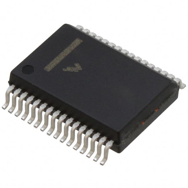
- Part No.:
- MCZ33880EWR2
- Manufacturer:
- NXP Semiconductors
- Package:
- 32-BSSOP (0.295", 7.50mm Width)
- Datasheet:
-
 MCZ33880EWR2.pdf
- Description:
- IC PWR SWITCH N-CHAN 1:8 32SOIC
- Quantity:
- Payment:

- Shipping:

Inventory:2,303
Please send an inquiry. Send us your inquiry, and we will respond immediately.
Product details
Overview
MCZ33880EWR2 from NXP Semiconductors (formerly Freescale) is a configurable octal high-side/low-side power switch IC with 8-bit SPI control and dual PWM-capable direct inputs (IN5, IN6). It delivers RDS(ON) ≤ 0.55 Ω at 25°C, supports VPWR = 5.5–24.5 V, provides ±45 V / −20 V output clamping, and drives incandescent or inductive loads up to 2.0 A per channel in automotive body electronics.
For engineers reviewing the MCZ33880EWR2 datasheet, MCZ33880EWR2 pinout, MCZ33880EWR2 application, or MCZ33880EWR2 equivalent, this page delivers verified electrical specs, thermal ground pin mapping for SOICW-32, fault reporting behavior via DO, and real-world implementation guidance for daisy-chained load switching in 12 V/24 V vehicle systems.
Technical Context
The MCZ33880EWR2 integrates SMARTMOS™ 5 mixed-signal technology-CMOS logic, bipolar/MOS analog circuitry, and independent double-diffused DMOS power transistors-to enable hardware-configurable high-side or low-side operation per channel. Its SPI interface operates up to 6 MHz with 3.3/5.0 V logic compatibility and supports cascaded fault reporting across multiple devices.
Each of the eight outputs features independent overtemperature shutdown (TLIM = 155–185°C), open-load detection (IOCO = 0.3–1.0 mA), short-circuit current limiting (0.8–2.0 A), and bidirectional transient clamping: +45 V (low-side) and −20 V (high-side), with internal reverse-battery protection on VPWR.
Key Specifications
| Parameter | Value and Actual Design Meaning |
|---|---|
| Supply Range (VPWR) | 5.5 V to 24.5 V - Enables direct connection to automotive battery rails including cold-crank (6 V) and load-dump (24.5 V) conditions. |
| RDS(ON) (25°C) | 0.55 Ω typical - Ensures <1.4 W conduction loss at 2 A, reducing thermal stress in compact PCB layouts. |
| Output Current Limit | 0.8 A to 2.0 A - Programmable per-channel current limiting protects against sustained overload without external sensing. |
| Clamp Voltage (LSD/HSD) | +45 V / −20 V - Suppresses inductive kickback during turn-off, eliminating need for external TVS diodes in most lamp/valve drivers. |
| Standby Current (IPWR) | 5.0 μA at 13 V, 95°C - Supports ultra-low-power sleep mode when VDD = 0 V and EN = 0 V, critical for always-on vehicle modules. |
| SPI Interface Speed | Up to 6.0 MHz - Allows full 8-bit command/status transfer in <1.33 μs, enabling rapid diagnostics in safety-critical lighting control. |
| Thermal Ground Pins | Pins 8, 9, 24, 25 (TGND) - Internally connected to die substrate; must be soldered to PCB ground plane to achieve RθJL = 18°C/W and sustain 1.7 W dissipation. |
Pinout & Package
MCZ33880EWR2 uses a 32-pin SOICW package (Case 1324-02) with four dedicated thermal ground pins (TGND) at positions 8, 9, 24, and 25. These pins are internally bonded to the die substrate and require low-impedance connection to the PCB ground plane for effective heat dissipation and stable operation above 125°C case temperature.
| Pin/Terminal | Circuit Role | Design Meaning |
|---|---|---|
| GND (Pin 1) | Digital reference ground | Reference for logic signals (VDD, CS, DI, SCLK, DO, IN5, IN6, EN); separate from power ground paths. |
| VDD (Pin 2) | Logic supply input | 5.0 V ±5% CMOS supply; undervoltage lockout triggers below 3.9 V to force all outputs OFF and enter low-current sleep state. |
| TGND (Pins 8, 9, 24, 25) | Thermal substrate ground | Direct die-to-PCB thermal path; must be connected to solid copper pour for RθJL = 18°C/W and junction temperature control. |
| CS (Pin 18) | SPI chip select | Active-low enable for SPI data transfer; falling edge latches status into shift register, rising edge updates outputs. |
| DO (Pin 32) | SPI fault status output | Tri-state output; driven low for no fault, high for any fault (open load, short, overtemp); MSB-first serial readout synchronized to SCLK. |
| IN5 / IN6 (Pins 19, 14) | PWM direct control inputs | OR-gated with SPI bits for Outputs 5 and 6; enables microcontroller PWM dimming without SPI overhead (max 2 kHz). |
| S1–S8 / D1–D8 (Pins 10,11,20,21,26,27,28,29,30,3–5,6,7,12,13,22,23) | Configurable source/drain terminals | Each pair (e.g., S1/D1) forms one MOSFET switch; Sx connects to load (HS) or GND (LS), Dx connects to VPWR (HS) or load (LS). |
Key Features
| Feature | Design Value |
|---|---|
| Hardware-configurable high/low-side topology | Each of 8 channels independently wired as HS or LS driver-no firmware reconfiguration needed for mixed-load systems. |
| Cascadable fault reporting | Single DO line reports faults across daisy-chained MCZ33880EWR2 devices, reducing MCU GPIO count and simplifying diagnostic firmware. |
| Independent per-output diagnostics | Open-load detection (0.3–1.0 mA threshold) and short-circuit current limit operate per channel without cross-talk or shared sensing resistors. |
| Integrated reverse-battery protection | VPWR pin withstands −16 V reverse polarity without external components-eliminates need for series diode or FET in battery-input designs. |
| Thermal ground-enhanced SOICW | Four dedicated TGND pins reduce junction-to-lead thermal resistance to 18°C/W, enabling 1.7 W continuous dissipation at TA = 25°C. |
Applications
| Automotive Lighting Control | Body Control Module (BCM) |
|---|---|
|
Use Scenario: Controlling headlamp, fog lamp, and interior dome lamps in modern vehicles with centralized BCM. IC Role / Device Role / Timing Role: Octal high-side switch driving 12 V incandescent/halogen lamps; configured as high-side with Sx → lamp, Dx → battery. Use Value: Eliminates discrete relay + driver circuits; RDS(ON) ≤ 0.55 Ω reduces heat generation vs. mechanical relays; integrated clamping prevents EMI from lamp inrush/turn-off. |
Use Scenario: Managing door locks, window motors, mirror actuators, and seat positioners via centralized electronic control unit. IC Role / Device Role / Timing Role: Configurable low-side driver for solenoids and small DC motors; Sx → GND, Dx → load, VPWR → battery. Use Value: Per-channel current limiting (0.8–2.0 A) prevents fuse blowing during motor stall; open-load detection identifies broken wires before field failure. |
| Industrial Valve & Actuator Control | Commercial Vehicle Trailer Control |
|
Use Scenario: Driving 24 V solenoid valves and pneumatic actuators in agricultural and construction equipment. IC Role / Device Role / Timing Role: High-side switch with VPWR = 24.5 V max; clamps inductive kick to +45 V during valve de-energization. Use Value: Replaces bulky discrete MOSFET + TVS + gate driver solutions; −20 V high-side clamp protects against negative transients in heavy-duty harnesses. |
Use Scenario: Implementing trailer lighting control (brake, turn, tail) with fault-tolerant communication over CAN-linked modules. IC Role / Device Role / Timing Role: Daisy-chained MCZ33880EWR2 devices report lamp faults via single DO line back to main controller. Use Value: Cascaded fault reporting reduces wiring complexity and enables real-time lamp-status monitoring without additional CAN messages. |
Equivalent & Alternatives
The following parts are listed as comparable options for similar octal high-side/low-side switch applications.
| Alternative Part | Technical Difference | Application Difference | Selection Advice |
|---|---|---|---|
| TPIC2810PWP | 8-channel, 50 V max, RDS(ON) = 0.8 Ω (typ), no integrated thermal ground pins, SPI-compatible but no PWM direct inputs. | Lacks IN5/IN6 PWM capability and TGND-enhanced thermal performance; suitable only for non-PWM, lower-current (<1.5 A) applications. | Choose TPIC2810PWP only if PWM dimming is unnecessary and board-level thermal management is handled externally. |
| STSPIN840TR | 8-channel, 45 V max, RDS(ON) = 0.65 Ω (typ), includes embedded current sense but no cascaded fault reporting or TGND pins. | Provides analog current monitoring but requires external ADC and firmware for fault interpretation; no DO-based daisy-chain support. | Prefer STSPIN840TR only when per-channel current measurement is mandatory and SPI fault reporting simplicity is secondary. |
Compared with TPIC2810PWP and STSPIN840TR, MCZ33880EWR2 uniquely combines hardware-configurable topology, dual PWM direct inputs, thermal-ground-optimized SOICW packaging, and true cascaded fault reporting-making it the only option supporting robust, low-software-overhead lamp/valve control in automotive-grade environments.
Availability
MCZ33880EWR2 is available at Aetrix Electronics and suitable for automotive lighting control, body control modules, and industrial actuator drive applications requiring stable component supply, long-term lifecycle support, and AEC-Q100-compliant sourcing.
Supply support for MCZ33880EWR2 includes scheduled delivery planning, volume procurement assistance, BOM continuity management, traceable sourcing, and lifecycle availability coordination for OEM customers, industrial embedded developers, connected-device designers, and electronics production programs.
Manufacturer
NXP Semiconductors is a global semiconductor leader focused on secure connectivity solutions for automotive, industrial, and IoT markets, with deep heritage in automotive power management from its Freescale acquisition.
The MCZ33880EWR2 belongs to NXP's SMARTMOS™ automotive power switch family, designed specifically for robust, fault-resilient control of resistive and inductive loads in harsh 12 V/24 V vehicle electrical systems.
FAQ
What is the maximum operating voltage for MCZ33880EWR2 on the VPWR pin?
The MCZ33880EWR2 supports VPWR from 5.5 V to 24.5 V under normal operation, with absolute maximum rating of −16 V to +50 V. This range accommodates automotive cold-crank (as low as 6 V) and load-dump (up to 24.5 V) events without damage or functional interruption, making MCZ33880EWR2 suitable for direct battery connection in body electronics modules.
How does the MCZ33880EWR2 handle fault reporting across multiple devices?
The MCZ33880EWR2 supports cascaded fault reporting via its DO pin: when multiple MCZ33880EWR2 devices are daisy-chained, the DO output of each device feeds into the DI input of the next. A single MCU SPI transaction reads fault status from all devices sequentially, eliminating the need for individual CS lines and reducing GPIO usage-critical for scalable lighting control systems.
Can MCZ33880EWR2 drive both high-side and low-side loads simultaneously?
Yes-MCZ33880EWR2 allows per-channel hardware configuration as either high-side or low-side switch. For example, Outputs 1–4 can be wired as high-side (Sx → load, Dx → battery) while Outputs 5–8 operate as low-side (Sx → GND, Dx → load), enabling mixed topology control within a single IC for complex vehicle subsystems like front/rear lighting clusters.
What thermal design considerations apply to MCZ33880EWR2 in SOICW-32 package?
MCZ33880EWR2's SOICW-32 package includes four thermal ground pins (8, 9, 24, 25) that must be soldered to a large PCB ground plane to achieve RθJL = 18°C/W. Without this, junction temperature rise exceeds safe limits under 2 A load; thermal vias under TGND pads and ≥2 oz copper are strongly recommended to maintain TJ < 150°C at 125°C ambient.
Does MCZ33880EWR2 support PWM dimming without SPI communication?
Yes-MCZ33880EWR2 provides two dedicated PWM-capable inputs: IN5 controls Output 5 and IN6 controls Output 6. These pins are OR-gated with their corresponding SPI bits, allowing direct microcontroller PWM signals (up to 2 kHz) to override SPI commands-enabling lamp dimming or motor speed control without interrupting the main SPI bus or adding software latency.
MCZ33880EWR2 Specifications
- Product attributes
- Attribute value
- Manufacturer:
- NXP Semiconductors
- Package/Case:
- 32-BSSOP (0.295", 7.50mm Width)
- Series:
- -
- Packaging:
- Tape & Reel (TR)
- Product Status:
- Obsolete
- Switch Type:
- General Purpose
- Number of Outputs:
- 8
- Ratio - Input:Output:
- 1:8
- Output Configuration:
- High Side or Low Side
- Output Type:
- N-Channel
- Interface:
- SPI
- Voltage - Load:
- 5.5V ~ 24.5V
- Voltage - Supply (Vcc/Vdd):
- 4.75V ~ 5.25V
- Current - Output (Max):
- 800mA
- Rds On (Typ):
- 550mOhm
- Input Type:
- -
- Features:
- -
- Fault Protection:
- Current Limiting (Fixed), Open Load Detect, Over Voltage
- Operating Temperature:
- -40°C ~ 150°C (TJ)
- Grade:
- -
- Qualification:
- -
- Mounting Type:
- Surface Mount
- Supplier Device Package:
- 32-SOIC
MCZ33880EWR2 FAQ
1.How can I place an order for MCZ33880EWR2 through Aetrix?
Please submit a Request for Quotation (RFQ) for MCZ33880EWR2 on Aetrix. Our sales agent will provide a competitive quotation and guide you through the order confirmation once you accept the terms.
2.Are the price and stock information for MCZ33880EWR2 reliable?
The price and inventory of MCZ33880EWR2 are updated periodically and may fluctuate due to market conditions. Stock and pricing data are typically refreshed every 24 hours. Quotation validity for MCZ33880EWR2 is usually 5 days.
3.What payment methods are accepted for MCZ33880EWR2?
We accept Wire Transfer, PayPal, Credit Card, Western Union, MoneyGram, and Escrow for MCZ33880EWR2 transactions.
Note: Certain payment methods may incur a processing fee.
4.How is shipping managed for MCZ33880EWR2?
MCZ33880EWR2 orders can be shipped via leading logistics carriers, including DHL, UPS, FedEx, TNT, or Registered Mail.
Once your MCZ33880EWR2 order is processed, you will receive an email with the shipment details and tracking number.
Note: Tracking information may take up to 24 hours to appear. Express delivery typically takes 3–5 business days.
5.How can I obtain technical support or documentation for MCZ33880EWR2?
For technical support, including MCZ33880EWR2 datasheets, pinout diagrams, or application guidance, please contact our engineering support team. They can provide detailed documentation and assistance for your MCZ33880EWR2 requirements.
6.How does Aetrix verify that MCZ33880EWR2 is sourced from the original manufacturer or authorized distributors?
All MCZ33880EWR2 products on Aetrix are procured from qualified distributors and authorized channels. Our dedicated quality assurance team conducts strict verification, including traceability checks and, if necessary, third-party testing. This ensures that MCZ33880EWR2 meets industry standards.
7.What is the process for return or replacement of MCZ33880EWR2?
All MCZ33880EWR2 units undergo pre-shipment inspection (PSI). If there is an issue with MCZ33880EWR2, returns or replacements are accepted under the following conditions:
1.Quantity discrepancies, incorrect items, or visible external defects (such as breakage or corrosion), acknowledged by Aetrix.
2.The issue is reported within 90 days of delivery.
3.The MCZ33880EWR2 part is unused and in its original packaging.
Return procedure for MCZ33880EWR2:
1.Submit a request within 90 days.
2.Obtain a Return Material Authorization (RMA) from Aetrix.
MCZ33880EWR2 Tags

-
TPS22919DCKR
Texas Instruments

-
MIC2091-1YM5-TR
Microchip Technology

-
MIC2090-1YM5-TR
Microchip Technology

-
TPS22995RZFR
Texas Instruments

-
TPS22975DSGR
Texas Instruments

-
SIP32510DT-T1-GE3
Vishay Siliconix

-
ULN2003D1013TR
STMicroelectronics

-
MIC2005A-1YM5-TR
Microchip Technology

-
MIC2005A-1YM6-TR
Microchip Technology

-
TPS22916BYFPR
Texas Instruments

-
TPS22917DBVR
Texas Instruments

-
ULN2003APWR
Texas Instruments
Tech Hub

A practical engineering guide to 3.3V and 5V logic compatibility, input thresholds, resistor dividers, translator ICs, MOSFET level shifting, I2C pull-ups, timing limits and power-sequencing risks.

The 74HC595 uses push-pull logic outputs, while the TPIC6B595 uses 50 V open-drain DMOS sinks for higher-power loads. This guide compares timing, current limits, 3.3 V interfacing, load wiring, thermal…

The 74HC595 converts serial data into eight stable parallel outputs. This guide covers pin functions, shift and storage timing, OE and MR behavior, drive-current limits, cascading, voltage compatibilit…

A technical comparison of level-sensitive latches and edge-triggered flip-flops, covering timing windows, setup and hold limits, master–slave operation, time borrowing, race-through, HDL inference and…

A D latch stores one bit while Enable controls when data can pass. This reference covers gate-level operation, truth tables, transparency, setup and hold timing, LE versus OE, common ICs and practical …

An SR latch stores one bit through cross-coupled feedback. This engineering reference covers NOR and NAND implementations, truth tables, forbidden-state recovery, gated operation, switch debouncing, fa…

Latch circuits retain one bit through feedback. This technical reference covers SR and D latches, truth tables, transparency, timing limits, latch-versus-flip-flop behavior, applications and common log…

An engineering guide to LED driver operation, constant-current and constant-voltage outputs, linear and switching topologies, dimming, IC selection, calculations, replacement compatibility, and fault c…

Operational amplifier guide covering op amp basics, feedback, ideal vs real op amps, common configurations, buffer circuits, offset, bias current, gain-bandwidth, slew rate, rail-to-rail limits and sel…

Jumper cables guide covering safe connection order, red and black clamp placement, final ground connection, cable gauge, length, clamp quality, copper vs CCA cables, jump starter comparison and battery…


