
 My Inquiry
 My Account


NXP Semiconductors MCZ33889DEGR2
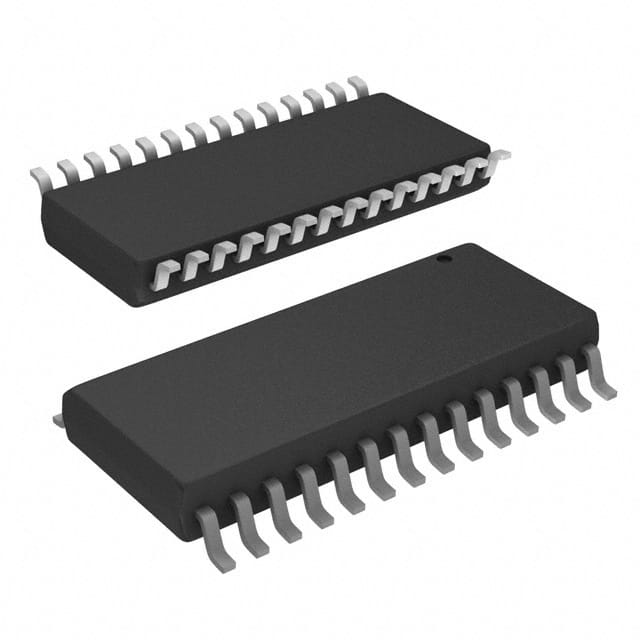
- Part No.:
- MCZ33889DEGR2
- Manufacturer:
- NXP Semiconductors
- Category:
- Specialized
- Package:
- 28-SOIC (0.295", 7.50mm Width)
- Datasheet:
-
 MCZ33889DEGR2.pdf
- Description:
- IC INTERFACE SPECIALIZED 28SOIC
- Quantity:
- Payment:

- Shipping:

Inventory:3,316
Please send an inquiry. Send us your inquiry, and we will respond immediately.
Product details
Overview
MCZ33889DEGR2 from NXP Semiconductors is a system basis chip (SBC) integrating a 5.0 V LDO regulator (200 mA), low-speed fault-tolerant CAN transceiver (125 kbps), dual-mode high-side switch (HS1), programmable watchdog, SPI interface, and four operational modes (Normal/Standby/Stop/Sleep). It powers microcontrollers and peripherals in automotive body electronics while providing bus wake-up, overtemperature prewarning, and supply monitoring.
For engineers reviewing the MCZ33889DEGR2 datasheet, MCZ33889DEGR2 pinout, MCZ33889DEGR2 application, or MCZ33889DEGR2 equivalent, this page delivers verified electrical specs, mode-dependent current consumption (e.g., 55–90 μA in Sleep2), CAN threshold differences between D/B variants, HS1 RDS(on) (≤5.0 Ω @ 125°C), and SPI timing compliance up to 4 MHz.
Technical Context
The MCZ33889DEGR2 implements a SMARTMOS-based architecture with two independent voltage regulation paths: VDD1 (5.0 V ±2%, 200 mA) for MCU supply and V2 (tracking regulator controlled via V2CTRL) for peripheral rails using an external PNP transistor. Its CAN physical layer complies with ISO 11898-3 for fault-tolerant operation at 125 kbps, featuring differential thresholds (VDIFF1 = 3.5 V min for recessive-to-dominant) and single-ended wake-up detection on CANH/CANL.
Four power modes are managed by internal state machine logic: Normal (full functionality), Standby (CAN active, reduced current), Stop (VDD1 on, oscillator optional), and Sleep (VDD1/V2 off, ultra-low ISUP = 55–90 μA). Wake-up sources include CAN bus activity, L0/L1 digital inputs, and external HS1-controlled signals - all with configurable deglitching and timeout.
Key Specifications
| Parameter | Value and Actual Design Meaning |
|---|---|
| VDD1 Output | 5.0 V ±2% at 200 mA load; drop voltage ≤0.2 V @ 50 mA enables stable MCU core supply under wide VSUP (4.5–27 V). |
| CAN Data Rate | 125 kbps max; fault-tolerant ISO 11898-3 compliant with dominant/recessive thresholds optimized for automotive ECU interconnect. |
| HS1 Switch | 150 mA output capability; RDS(on) ≤5.0 Ω @ 125°C supports driving relays or pull-up resistors without external FET. |
| SPI Interface | 4 MHz max clock frequency; t2SPI = 25 μs minimum inter-message delay ensures reliable register access in safety-critical firmware. |
| Sleep Current | 55–90 μA (Sleep2 mode, oscillator off); enables battery-conscious always-on modules in vehicle entry systems. |
| Watchdog Periods | Configurable periods: 9.75 ms / 45 ms / 100 ms / 350 ms (Normal mode); accuracy ±12% guarantees deterministic fail-safe timing. |
| Operating Temp | -40°C to +125°C ambient; thermal shutdown at 160–190°C protects against sustained overload in engine bay environments. |
Pinout & Package
MCZ33889DEGR2 is housed in a 28-pin SOICW (wide-body) package with exposed thermal pad, Pb-free (RoHS-compliant) finish, and 1.27 mm pitch. Pin layout supports automotive PCB routing with dedicated ground pins (6,7,8,9,20,21,22,23) for thermal dissipation and noise immunity.
| Pin/Terminal | Circuit Role | Design Meaning |
|---|---|---|
| RX | CAN Receiver Output | Delivers decoded CAN bus data to MCU; open-drain compatible with 5 V logic levels. |
| TX | CAN Transmitter Input | Accepts MCU-generated CAN frames; level-shifted to match V2 domain for peripheral isolation. |
| VDD1 | Main Regulator Output | 5.0 V supply for MCU core; includes current limiting, overtemperature prewarning, and reset assertion. |
| RST | Reset Output | Active-low reset signal synchronized to VDD1 stability; threshold selectable via SPI (4.2 V or 4.6 V). |
| INT | Interrupt Output | Asserts LOW on enabled events (watchdog timeout, supply fault, CAN error); debounced and maskable. |
| V2CTRL | V2 Regulator Control | Drives base of external PNP transistor to generate tracked V2 rail; sink current ≥10 mA. |
| VSUP | Main Supply Input | Accepts 4.5–27 V DC; withstands load dump (40 V transient) and jump-start (27 V) per ISO 7637. |
| HS1 | High-Side Switch Output | Switches battery voltage to external loads; current-limited to 160–500 mA with thermal foldback. |
| L0 / L1 | Wake-Up Inputs | Digital wake sources with hysteresis (0.6–1.3 V); support direct connection to door/trunk switches. |
| V2 | Peripheral Regulator Input | Input for externally generated 5.0 V rail; monitors V2LOW flag if voltage drops below 3.75–4.25 V. |
| RTH / RTL | Termination Control | Drive termination resistors to CANH/CANL; enable/disable bus termination via SPI command. |
| CANH / CANL | CAN Bus Interface | Fault-tolerant differential outputs; withstand ±40 V transients and support short-to-battery detection. |
| SCLK / MOSI / MISO / CS | SPI Interface | Full-duplex serial control; CS-active timing defines register access window and mode transitions. |
| WDOG | Watchdog Output | Open-drain indicator of watchdog expiration; pulls LOW if not refreshed within programmed period. |
Key Features
| Feature | Design Value |
|---|---|
| Integrated VDD1 LDO | 5.0 V ±2% regulator with 200 mA output, current limit, and overtemperature prewarning (TPW = 130–160°C) for safe MCU power delivery. |
| Configurable Power Modes | Four distinct states (Normal/Standby/Stop/Sleep) with sub-100 μA sleep current and programmable wake-up sources for energy optimization. |
| Fault-Tolerant CAN PHY | ISO 11898-3 compliant transceiver with 125 kbps rate, differential thresholds (VDIFF1 = 3.5 V min), and bus failure recovery (e.g., open-wire after 4 consecutive pulses). |
| Programmable Watchdog | Four selectable time windows (9.75–350 ms), ±12% accuracy, and stop-mode support ensure robust software supervision across all operating conditions. |
| HS1 High-Side Driver | 150 mA capable switch with RDS(on) ≤5.0 Ω @ 125°C and built-in overtemperature shutdown (155–190°C) for direct relay/load control. |
| V2 Tracking Regulator | V2CTRL output drives external PNP to generate matched peripheral voltage; supports flexible rail design with V2LOW flag monitoring. |
Applications
| Body Control Module (BCM) | Door Module |
|---|---|
Use Scenario: Centralized management of lighting, locks, windows, and mirrors in modern vehicles. IC Role / Device Role / Timing Role: MCZ33889DEGR2 serves as primary power manager and CAN node controller, supplying MCU and peripherals while enabling wake-up via door handle switches (L0/L1) or CAN traffic. Use Value: Integrated VDD1/V2 regulators eliminate discrete LDOs; fault-tolerant CAN ensures reliable communication during bus faults like short-to-battery. | Use Scenario: Local control unit inside vehicle doors handling window lift, mirror adjustment, and intrusion detection. IC Role / Device Role / Timing Role: MCZ33889DEGR2 provides isolated 5 V rails (VDD1 for MCU, V2 for sensors/motors), HS1-driven motor control, and CAN connectivity with wake-on-CANL/H. Use Value: Ultra-low sleep current (55–90 μA) extends battery life during vehicle standby; CAN wake-up eliminates need for separate wake lines. |
| Seat Control Unit | Roof Module |
Use Scenario: Motorized seat position memory, heating, and lumbar support in premium automotive interiors. IC Role / Device Role / Timing Role: MCZ33889DEGR2 supplies power to seat MCU and motor drivers, monitors supply health, and communicates seat status via CAN bus. Use Value: HS1 switch directly drives seat heater relays; programmable watchdog prevents lockup during complex motor sequencing. | Use Scenario: Sunroof, panoramic roof, or ambient lighting control with integrated rain/light sensors. IC Role / Device Role / Timing Role: MCZ33889DEGR2 manages power to MCU and sensor interfaces, enables wake-up from sunroof switch inputs (L0/L1), and reports status over CAN. Use Value: Dual-regulator architecture isolates sensitive analog sensors (V2) from noisy motor switching (VDD1); RTH/RTL pins simplify bus termination control. |
Equivalent & Alternatives
The following parts are listed as comparable options for similar system basis chip applications.
| Alternative Part | Technical Difference | Application Difference | Selection Advice |
|---|---|---|---|
| MC33886DEGR2 | Higher-current H-bridge driver (5 A) replaces HS1; lacks integrated CAN transceiver and V2 tracking regulator. | Targeted at motor control only; requires external CAN PHY and power management ICs for full SBC functionality. | Select when high-power motor actuation dominates over communication and multi-rail power needs. |
| TCAN1042DRBR | Dedicated CAN transceiver only; no regulators, watchdog, SPI, or wake-up inputs - purely physical layer device. | Used as CAN PHY supplement in designs with separate power management; cannot replace MCZ33889DEGR2's integrated SBC functions. | Choose only as CAN interface add-on where existing power architecture already meets system requirements. |
Compared with MC33889DEGR2, MC33886DEGR2 trades CAN integration and dual regulation for higher motor drive capability, while TCAN1042DRBR offers superior CAN ESD performance (+8 kV contact) but zero power management - making MCZ33889DEGR2 uniquely suited for compact, self-contained automotive nodes requiring regulated power, communication, and supervision in one die.
Availability
MCZ33889DEGR2 is available at Aetrix Electronics and suitable for automotive body electronics, door modules, seat control units, and roof modules requiring stable component supply across extended temperature ranges and long production lifecycles.
Supply support for MCZ33889DEGR2 includes scheduled delivery planning, volume procurement assistance, BOM continuity management, traceable sourcing, and lifecycle availability coordination for OEM customers, industrial embedded developers, connected-device designers, and electronics production programs.
Manufacturer
NXP Semiconductors is a global semiconductor leader specializing in secure connectivity solutions for automotive, industrial, and IoT applications.
The MCZ33889DEGR2 belongs to NXP's System Basis Chip product line, engineered specifically for automotive electronic control units needing integrated power management, fault-tolerant CAN communication, and intelligent wake-up capabilities in harsh environments.
FAQ
What is the maximum supply voltage rating for MCZ33889DEGR2?
The MCZ33889DEGR2 supports a continuous VSUP range of 4.5 V to 27 V, with transient tolerance up to 40 V during load dump events per ISO 7637-2 Pulse 5a. This ensures robust operation in 12 V and 24 V automotive systems where voltage spikes are common. The device remains fully functional across the extended 4.5–5.5 V and 18–27 V ranges, though some features like oscillator operation may be limited outside nominal 5.5–18 V.
How does the MCZ33889DEGR2 differ from the MC33889B variant?
The MCZ33889DEGR2 (D version) differs from the B version primarily in CAN receiver thresholds and loop timing: VDIFF1 min is 3.5 V (vs. 3.2 V for B), tLOOPRD max is 1.5 μs (vs. N/A for B), and wake-up detection on CANL/CANH requires ≥16 μs dominant time (vs. ≥30 μs for B). These tighter tolerances improve noise immunity and bus recovery speed in electrically noisy vehicle networks, making MCZ33889DEGR2 preferred for new designs demanding enhanced fault tolerance.
Can MCZ33889DEGR2 operate in battery-less systems or with backup power sources?
Yes - MCZ33889DEGR2 supports TermVbat mode, where CANH/CANL receivers remain active even when VSUP is disconnected, allowing wake-up from bus traffic during battery disconnect scenarios. In this mode, V2INT must be maintained at 0–5.25 V, and CANH/CANL short-to-battery detection uses reduced thresholds (VSUP/2 + 4.55 V). This enables fail-operational behavior in redundant power architectures used in ADAS and gateway modules.
What is the purpose of the RTH and RTL pins on MCZ33889DEGR2?
The RTH and RTL pins on MCZ33889DEGR2 provide active control of CAN bus termination resistors. RTH connects to CANH and RTL to CANL, allowing the SBC to enable or disable termination via SPI commands. This eliminates manual resistor placement and supports dynamic network topology changes - such as adding/removing ECUs - without hardware modification. Each pin has programmable on-resistance (10–90 Ω) and supports both normal and TermVbat modes.
Does MCZ33889DEGR2 support SPI communication during Stop or Sleep modes?
Yes - MCZ33889DEGR2 allows SPI wake-up and configuration during Stop mode: a rising edge on CS initiates normal request mode within 15–90 μs, enabling immediate register access. However, SPI is disabled in Sleep mode; wake-up requires L0/L1 input or CAN activity first. This design balances ultra-low power consumption with responsive reconfiguration - critical for systems that must react quickly to external events while minimizing quiescent current.
MCZ33889DEGR2 Specifications
- Product attributes
- Attribute value
- Manufacturer:
- NXP Semiconductors
- Series:
- -
- Package/Case:
- 28-SOIC (0.295", 7.50mm Width)
- Packaging:
- Tape & Reel (TR)
- Product Status:
- Obsolete
- Applications:
- System Basis Chip
- Interface:
- CAN, SPI
- Voltage - Supply:
- 5.5V ~ 18V
- Supplier Device Package:
- 28-SOIC
- Grade:
- -
- Qualification:
- -
- Mounting Type:
- Surface Mount
MCZ33889DEGR2 FAQ
1.How can I place an order for MCZ33889DEGR2 through Aetrix?
Please submit a Request for Quotation (RFQ) for MCZ33889DEGR2 on Aetrix. Our sales agent will provide a competitive quotation and guide you through the order confirmation once you accept the terms.
2.Are the price and stock information for MCZ33889DEGR2 reliable?
The price and inventory of MCZ33889DEGR2 are updated periodically and may fluctuate due to market conditions. Stock and pricing data are typically refreshed every 24 hours. Quotation validity for MCZ33889DEGR2 is usually 5 days.
3.What payment methods are accepted for MCZ33889DEGR2?
We accept Wire Transfer, PayPal, Credit Card, Western Union, MoneyGram, and Escrow for MCZ33889DEGR2 transactions.
Note: Certain payment methods may incur a processing fee.
4.How is shipping managed for MCZ33889DEGR2?
MCZ33889DEGR2 orders can be shipped via leading logistics carriers, including DHL, UPS, FedEx, TNT, or Registered Mail.
Once your MCZ33889DEGR2 order is processed, you will receive an email with the shipment details and tracking number.
Note: Tracking information may take up to 24 hours to appear. Express delivery typically takes 3–5 business days.
5.How can I obtain technical support or documentation for MCZ33889DEGR2?
For technical support, including MCZ33889DEGR2 datasheets, pinout diagrams, or application guidance, please contact our engineering support team. They can provide detailed documentation and assistance for your MCZ33889DEGR2 requirements.
6.How does Aetrix verify that MCZ33889DEGR2 is sourced from the original manufacturer or authorized distributors?
All MCZ33889DEGR2 products on Aetrix are procured from qualified distributors and authorized channels. Our dedicated quality assurance team conducts strict verification, including traceability checks and, if necessary, third-party testing. This ensures that MCZ33889DEGR2 meets industry standards.
7.What is the process for return or replacement of MCZ33889DEGR2?
All MCZ33889DEGR2 units undergo pre-shipment inspection (PSI). If there is an issue with MCZ33889DEGR2, returns or replacements are accepted under the following conditions:
1.Quantity discrepancies, incorrect items, or visible external defects (such as breakage or corrosion), acknowledged by Aetrix.
2.The issue is reported within 90 days of delivery.
3.The MCZ33889DEGR2 part is unused and in its original packaging.
Return procedure for MCZ33889DEGR2:
1.Submit a request within 90 days.
2.Obtain a Return Material Authorization (RMA) from Aetrix.
MCZ33889DEGR2 Tags

-
NVT4857UKAZ
NXP Semiconductors

-
TCA8418RTWR
Texas Instruments

-
PCA9546APWR
Texas Instruments

-
MD0100N8-G
Microchip Technology

-
PCA9548APW,118
NXP Semiconductors

-
PCA9540BDP,118
NXP Semiconductors

-
PCA9548APWR
Texas Instruments

-
PCA9546APW,118
NXP Semiconductors

-
PTN3360DBS,518
NXP Semiconductors

-
PCA9546ABS,118
NXP Semiconductors

-
PCA9518PWR
Texas Instruments

-
PCA9545APW,118
NXP Semiconductors
Tech Hub

A practical engineering guide to 3.3V and 5V logic compatibility, input thresholds, resistor dividers, translator ICs, MOSFET level shifting, I2C pull-ups, timing limits and power-sequencing risks.

The 74HC595 uses push-pull logic outputs, while the TPIC6B595 uses 50 V open-drain DMOS sinks for higher-power loads. This guide compares timing, current limits, 3.3 V interfacing, load wiring, thermal…

The 74HC595 converts serial data into eight stable parallel outputs. This guide covers pin functions, shift and storage timing, OE and MR behavior, drive-current limits, cascading, voltage compatibilit…

A technical comparison of level-sensitive latches and edge-triggered flip-flops, covering timing windows, setup and hold limits, master–slave operation, time borrowing, race-through, HDL inference and…

A D latch stores one bit while Enable controls when data can pass. This reference covers gate-level operation, truth tables, transparency, setup and hold timing, LE versus OE, common ICs and practical …

An SR latch stores one bit through cross-coupled feedback. This engineering reference covers NOR and NAND implementations, truth tables, forbidden-state recovery, gated operation, switch debouncing, fa…

Latch circuits retain one bit through feedback. This technical reference covers SR and D latches, truth tables, transparency, timing limits, latch-versus-flip-flop behavior, applications and common log…

An engineering guide to LED driver operation, constant-current and constant-voltage outputs, linear and switching topologies, dimming, IC selection, calculations, replacement compatibility, and fault c…

Operational amplifier guide covering op amp basics, feedback, ideal vs real op amps, common configurations, buffer circuits, offset, bias current, gain-bandwidth, slew rate, rail-to-rail limits and sel…

Jumper cables guide covering safe connection order, red and black clamp placement, final ground connection, cable gauge, length, clamp quality, copper vs CCA cables, jump starter comparison and battery…


