
 My Inquiry
 My Account


NXP Semiconductors MCZ33970EGR2
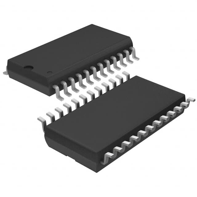
- Part No.:
- MCZ33970EGR2
- Manufacturer:
- NXP Semiconductors
- Category:
- Motor Drivers, Controllers
- Package:
- 24-SOIC (0.295", 7.50mm Width)
- Datasheet:
-
 MCZ33970EGR2.pdf
- Description:
- IC MTR DRV BIPLR 4.5-5.5V 24SOIC
- Quantity:
- Payment:

- Shipping:

Inventory:4,368
Please send an inquiry. Send us your inquiry, and we will respond immediately.
Product details
Overview
MCZ33970EGR2 from NXP Semiconductors (formerly Freescale) is a dual two-phase stepper motor gauge driver IC for automotive instrumentation clusters. It integrates four H-bridge drivers, SPI-controlled position/velocity state machine, air-core pointer movement emulation, 4096-step resolution, 340° sweep, and supports 400°/s max velocity with 4500°/s² acceleration - deployed in digital instrument clusters replacing analog air-core meters.
For engineers reviewing the MCZ33970EGR2 datasheet, MCZ33970EGR2 pinout, MCZ33970EGR2 application, or MCZ33970EGR2 equivalent, key selection considerations include its SPI-configurable dual-gauge control, analog microstepping (12 steps/degree), RTZ (Return-to-Zero) accumulator diagnostics, calibrated internal oscillator (±10%), and Pb-free 24-pin SOICW package rated for -40°C to 125°C operation.
Technical Context
The MCZ33970EGR2 implements a ROM-based motion profile state machine that executes acceleration/deceleration trajectories using precomputed step timing tables synchronized to its software-calibratable 1.0 MHz oscillator. Each of its two independent gauge channels drives sine/cosine coil pairs via dedicated H-bridge outputs (SIN0±/COS0± and SIN1±/COS1±) with linear current sourcing/sinking up to 40 mA per output.
It features integrated VPWR overvoltage (26–38 V) and undervoltage (5.0–6.2 V) detection, thermal shutdown at 155–180°C, and real-time status reporting via SPI - including MOV0/MOV1 motion flags, RTZ accumulator counts, coil output confirmation, and clock calibration fault indicators - all while maintaining <60 µA sleep current with RST asserted.
Key Specifications
| Parameter | Value and Actual Design Meaning |
|---|---|
| Supply Voltage (VPWR) | 6.5–26 V - powers H-bridge outputs; includes overvoltage lockout at 32 V nominal |
| Logic Supply (VDD) | 4.5–5.5 V - powers SPI interface and internal logic; reset asserts below 4.5 V |
| Output Current (per H-bridge half) | 40 mA continuous - sufficient to drive typical 2-phase instrumentation stepper coils (e.g., MMT AFIC-6405 compatible) |
| Pointer Resolution | 4096 positions - enables sub-degree positioning accuracy across 340° mechanical sweep |
| Max Pointer Velocity | 400°/s - achievable only with calibrated 1.0 MHz internal clock; scales linearly with clock frequency |
| Max Acceleration | 4500°/s² - fixed profile derived from ROM timing table; not user-programmable |
| SPI Clock Frequency | 1.0–3.0 MHz - supports daisy-chained configurations; timing compliant with standard SPI mode 0/3 |
| Operating Temperature | -40°C to 125°C - qualified for under-hood and cluster-mount automotive environments |
Pinout & Package
MCZ33970EGR2 uses a 24-pin SOICW (Small Outline Integrated Circuit, Wide-body) package with exposed thermal pad (not electrically connected), Pb-free (EG suffix), and moisture sensitivity level (MSL) 3 per JEDEC J-STD-020C.
| Pin/Terminal | Circuit Role | Design Meaning |
|---|---|---|
| 1–4, 21–24 | H-Bridge Outputs (COS0+, COS0−, SIN0+, SIN0−, SIN1−, SIN1+, COS1−, COS1+) | Eight dedicated half-bridge terminals driving two independent 2-phase stepper motors; each sources/sinks up to 40 mA with flyback clamping |
| 5–8, 17–20 | GND | Eight ground pins - provide low-impedance return paths for H-bridge power and logic; also serve as thermal conduction path |
| 9 | CS | Chip Select input - enables SPI communication; internal pull-up; must be low during SCLK transitions |
| 10 | SCLK | Serial Clock input - clocks SI data on falling edge and SO data on rising edge; internal pull-down |
| 11 | SO | Serial Output - tri-stateable; outputs 16-bit status word first, then FIFO data; high-impedance when CS = high |
| 12 | SI | Serial Input - accepts 16-bit SPI command words MSB-first on falling SCLK edges; ignored when CS = high |
| 13 | RTZ | Multiplexed output - drives non-driven coil during Return-to-Zero sequence; used for RTZ accumulator measurement |
| 14 | VDD | 5.0 V logic supply - powers SPI interface, state machine, and internal regulators; UVLO at 4.5 V |
| 15 | RST | Active-low reset - forces internal logic to default state; internal active pull-up; asserts sleep mode when held low |
| 16 | VPWR | Battery input - supplies H-bridge drivers; monitored for over/undervoltage faults; operates from 6.5–26 V |
Key Features
| Feature | Design Value |
|---|---|
| Analog microstepping (12 steps/degree) | Enables smooth, jitter-free pointer motion indistinguishable from air-core meter behavior - reduces MCU processing load vs. digital step generation |
| Software-calibratable oscillator (±10%) | Allows precise velocity/acceleration tuning using external 8 µs pulse on CS pin - eliminates need for external crystal or precision RC network |
| Integrated RTZ accumulator with diagnostic readout | Measures actual coil current decay during zeroing sequence - provides fault detection for open/shorted coils or mechanical binding |
| Dual independent gauge control registers | Separate POS0R/POS1R, VELR, and RTZR registers enable asynchronous positioning of two gauges without cross-interference |
| Backward compatibility with MC33991 | Shares register map and command protocol - allows drop-in replacement in legacy designs with minimal firmware changes |
| Low sleep current (≤60 µA) | Supports always-on cluster architectures - maintains RTC and wake-on-event capability while minimizing battery drain |
Applications
| Digital Instrument Cluster | Automotive HVAC Display |
|---|---|
Use Scenario: Centralized dashboard with speedometer, tachometer, fuel, and temperature gauges driven by single ECU. IC Role / Device Role / Timing Role: Dual-gauge driver IC executing closed-loop pointer positioning via SPI commands; manages acceleration profiles and RTZ sequences autonomously. Use Value: Replaces four discrete air-core meters with two compact stepper motors - reduces BOM cost, weight, and EMI emissions while enabling dynamic UI reconfiguration. |
Use Scenario: Climate control panel with rotary blower speed and temperature setpoint indicators. IC Role / Device Role / Timing Role: Dedicated gauge controller for auxiliary instrumentation; interfaces via shared SPI bus with main cluster MCU. Use Value: Enables consistent pointer motion quality across primary and secondary displays using same calibration and microstepping algorithm - simplifies system-level validation. |
| Electric Vehicle Battery SOC Gauge | Commercial Vehicle Diagnostic Panel |
Use Scenario: High-accuracy state-of-charge indicator requiring logarithmic scaling and thermal derating compensation. IC Role / Device Role / Timing Role: Precision gauge driver receiving scaled position commands from battery management system; uses RTZ accumulator to verify mechanical integrity before startup. Use Value: Provides deterministic pointer response to SOC transitions - avoids visual lag or overshoot seen with PWM-driven analog meters under rapid voltage changes. |
Use Scenario: Heavy-duty truck cab display showing oil pressure, coolant temp, and air brake status with fault-tolerant zeroing. IC Role / Device Role / Timing Role: Robust gauge interface with built-in VPWR monitoring, overtemperature shutdown, and diagnostic-ready RTZ reporting. Use Value: Eliminates need for external watchdog or sensor fusion logic - detects open-circuit coils or seized mechanisms before field failure. |
Equivalent & Alternatives
The following parts are listed as comparable options for similar dual stepper gauge driver applications.
| Alternative Part | Technical Difference | Application Difference | Selection Advice |
|---|---|---|---|
| MC33991DG | Lacks analog microstepping; uses digital step sequencing; no RTZ accumulator; 32-pin SOICW package | Requires higher MCU bandwidth for motion profile generation; limited diagnostic visibility into coil health | Select when legacy firmware compatibility is critical and microstepping smoothness is secondary |
| AS8510BQFT | Single-channel design; SPI + I²C interface; integrated 10-bit ADC for coil sensing; QFN-32 package | Needs two devices for dual-gauge systems; adds coil current monitoring but increases layout complexity | Select when coil current feedback and multi-protocol flexibility outweigh dual-channel integration benefits |
Compared with MC33991DG and AS8510BQFT, the MCZ33970EGR2 uniquely delivers factory-tuned analog microstepping, integrated RTZ diagnostics, and true dual-gauge autonomy in a single 24-pin SOICW - reducing system-level firmware overhead and PCB area while enhancing pointer motion fidelity and field reliability.
Availability
MCZ33970EGR2 is available at Aetrix Electronics and suitable for automotive instrument clusters, EV battery SOC displays, commercial vehicle diagnostic panels, and HVAC interface modules requiring stable component supply across extended temperature ranges and long production lifecycles.
Supply support for MCZ33970EGR2 includes scheduled delivery planning, volume procurement assistance, BOM continuity management, traceable sourcing, and lifecycle availability coordination for OEM customers, industrial embedded developers, connected-device designers, and electronics production programs.
Manufacturer
NXP Semiconductors is a global semiconductor leader focused on secure connectivity solutions for automotive, industrial, and IoT applications - formed from the spin-off of Freescale Semiconductor and NXP in 2015.
The MCZ33970EGR2 belongs to NXP's automotive analog front-end (AFE) product line, designed specifically to replace electromechanical air-core meters with digitally controlled stepper motor instrumentation - emphasizing motion fidelity, diagnostic depth, and AEC-Q100 Grade 1 qualification.
FAQ
What is the maximum operating temperature range for the MCZ33970EGR2?
The MCZ33970EGR2 is qualified for operation from -40°C to +125°C ambient temperature, with junction temperature rated up to +150°C. Its thermal resistance (RθJA) is 60°C/W, and it includes internal overtemperature shutdown that activates between 155°C and 180°C - making it suitable for under-dash and engine-compartment-adjacent automotive instrument cluster placements where thermal management is critical. The MCZ33970EGR2 maintains full functionality across this range when mounted on standard FR-4 PCBs with recommended copper pour.
Does the MCZ33970EGR2 require an external crystal or resonator?
No, the MCZ33970EGR2 uses an internal RC oscillator that can be software-calibrated to ±10% accuracy using an 8 µs pulse on the CS pin - eliminating the need for external timing components. The uncalibrated oscillator operates between 0.65 µs and 1.7 µs per cycle (≈588 kHz to 1.54 MHz), and calibration centers it at 1.0 MHz. This feature reduces BOM count and board space while ensuring repeatable pointer velocity and acceleration. The MCZ33970EGR2 does not support external clock injection.
How does the MCZ33970EGR2 implement Return-to-Zero (RTZ) diagnostics?
The MCZ33970EGR2 performs RTZ by driving one coil while measuring current decay on the complementary coil via the RTZ pin - converting the decay time into an accumulator count readable through the RTZR register. This count reflects coil inductance, resistance, and mechanical load, enabling detection of open circuits, shorted windings, or seized gears. The MCZ33970EGR2 reports RTZ completion status and fault flags via SPI status bits, allowing the host MCU to validate gauge health before initialization - a capability absent in basic stepper drivers.
Can the MCZ33970EGR2 drive stepper motors other than MMT-licensed types?
Yes, the MCZ33970EGR2 can drive any two-phase bipolar stepper motor with coil current ≤40 mA per half-bridge and coil voltage ≤6 V (measured across SIN/COS pairs). Its analog microstepping architecture is optimized for instrumentation-grade steppers like the MMT AFIC-6405, but electrical compatibility extends to generic 2-phase 20–30 Ω, 5–6 V coils. Motor-specific tuning (e.g., acceleration profile adjustment) is not supported - the MCZ33970EGR2 uses fixed ROM-based timing tables.
What SPI configuration does the MCZ33970EGR2 require?
The MCZ33970EGR2 uses a standard 3-wire SPI interface (CS, SCLK, SI/SO) operating in Mode 0 (CPOL=0, CPHA=0) or Mode 3 (CPOL=1, CPHA=1), with 16-bit words MSB-first. SCLK must be 1.0–3.0 MHz; setup/hold times are specified down to 25 ns. The device supports daisy-chaining via SI→SO routing between multiple MCZ33970EGR2 units. All commands and status reads occur through the same 16-bit SPI port - no separate I²C or UART interface exists in the MCZ33970EGR2.
MCZ33970EGR2 Specifications
- Product attributes
- Attribute value
- Manufacturer:
- NXP Semiconductors
- Series:
- -
- Package/Case:
- 24-SOIC (0.295", 7.50mm Width)
- Packaging:
- Tape & Reel (TR)
- Product Status:
- Obsolete
- Motor Type - Stepper:
- Bipolar
- Motor Type - AC, DC:
- -
- Function:
- Driver - Fully Integrated, Control and Power Stage
- Output Configuration:
- Half Bridge (8)
- Interface:
- SPI
- Technology:
- -
- Step Resolution:
- -
- Applications:
- -
- Current - Output:
- 40mA
- Voltage - Supply:
- 4.5V ~ 5.5V
- Voltage - Load:
- 6.5V ~ 26V
- Operating Temperature:
- -40°C ~ 150°C (TJ)
- Grade:
- Automotive
- Qualification:
- -
- Mounting Type:
- Surface Mount
- Supplier Device Package:
- 24-SOIC
MCZ33970EGR2 FAQ
1.How can I place an order for MCZ33970EGR2 through Aetrix?
Please submit a Request for Quotation (RFQ) for MCZ33970EGR2 on Aetrix. Our sales agent will provide a competitive quotation and guide you through the order confirmation once you accept the terms.
2.Are the price and stock information for MCZ33970EGR2 reliable?
The price and inventory of MCZ33970EGR2 are updated periodically and may fluctuate due to market conditions. Stock and pricing data are typically refreshed every 24 hours. Quotation validity for MCZ33970EGR2 is usually 5 days.
3.What payment methods are accepted for MCZ33970EGR2?
We accept Wire Transfer, PayPal, Credit Card, Western Union, MoneyGram, and Escrow for MCZ33970EGR2 transactions.
Note: Certain payment methods may incur a processing fee.
4.How is shipping managed for MCZ33970EGR2?
MCZ33970EGR2 orders can be shipped via leading logistics carriers, including DHL, UPS, FedEx, TNT, or Registered Mail.
Once your MCZ33970EGR2 order is processed, you will receive an email with the shipment details and tracking number.
Note: Tracking information may take up to 24 hours to appear. Express delivery typically takes 3–5 business days.
5.How can I obtain technical support or documentation for MCZ33970EGR2?
For technical support, including MCZ33970EGR2 datasheets, pinout diagrams, or application guidance, please contact our engineering support team. They can provide detailed documentation and assistance for your MCZ33970EGR2 requirements.
6.How does Aetrix verify that MCZ33970EGR2 is sourced from the original manufacturer or authorized distributors?
All MCZ33970EGR2 products on Aetrix are procured from qualified distributors and authorized channels. Our dedicated quality assurance team conducts strict verification, including traceability checks and, if necessary, third-party testing. This ensures that MCZ33970EGR2 meets industry standards.
7.What is the process for return or replacement of MCZ33970EGR2?
All MCZ33970EGR2 units undergo pre-shipment inspection (PSI). If there is an issue with MCZ33970EGR2, returns or replacements are accepted under the following conditions:
1.Quantity discrepancies, incorrect items, or visible external defects (such as breakage or corrosion), acknowledged by Aetrix.
2.The issue is reported within 90 days of delivery.
3.The MCZ33970EGR2 part is unused and in its original packaging.
Return procedure for MCZ33970EGR2:
1.Submit a request within 90 days.
2.Obtain a Return Material Authorization (RMA) from Aetrix.
MCZ33970EGR2 Tags

-
DRV2603RUNR
Texas Instruments

-
DRV8837CDSGR
Texas Instruments

-
DRV8837DSGR
Texas Instruments
-
DRV8838DSGR
Texas Instruments

-
DRV8839DSSR
Texas Instruments

-
EMC2301-1-ACZL-TR
Microchip Technology
-
DRV8231ADSGR
Texas Instruments

-
EMC2302-2-AIZL-TR
Microchip Technology

-
DRV8800PWPR
Texas Instruments
-
DRV8835DSSR
Texas Instruments

-
EMC2303-1-KP-TR
Microchip Technology

-
DRV8876PWPR
Texas Instruments
Tech Hub

A practical engineering guide to 3.3V and 5V logic compatibility, input thresholds, resistor dividers, translator ICs, MOSFET level shifting, I2C pull-ups, timing limits and power-sequencing risks.

The 74HC595 uses push-pull logic outputs, while the TPIC6B595 uses 50 V open-drain DMOS sinks for higher-power loads. This guide compares timing, current limits, 3.3 V interfacing, load wiring, thermal…

The 74HC595 converts serial data into eight stable parallel outputs. This guide covers pin functions, shift and storage timing, OE and MR behavior, drive-current limits, cascading, voltage compatibilit…

A technical comparison of level-sensitive latches and edge-triggered flip-flops, covering timing windows, setup and hold limits, master–slave operation, time borrowing, race-through, HDL inference and…

A D latch stores one bit while Enable controls when data can pass. This reference covers gate-level operation, truth tables, transparency, setup and hold timing, LE versus OE, common ICs and practical …

An SR latch stores one bit through cross-coupled feedback. This engineering reference covers NOR and NAND implementations, truth tables, forbidden-state recovery, gated operation, switch debouncing, fa…

Latch circuits retain one bit through feedback. This technical reference covers SR and D latches, truth tables, transparency, timing limits, latch-versus-flip-flop behavior, applications and common log…

An engineering guide to LED driver operation, constant-current and constant-voltage outputs, linear and switching topologies, dimming, IC selection, calculations, replacement compatibility, and fault c…

Operational amplifier guide covering op amp basics, feedback, ideal vs real op amps, common configurations, buffer circuits, offset, bias current, gain-bandwidth, slew rate, rail-to-rail limits and sel…

Jumper cables guide covering safe connection order, red and black clamp placement, final ground connection, cable gauge, length, clamp quality, copper vs CCA cables, jump starter comparison and battery…


