
 My Inquiry
 My Account


NXP Semiconductors MCZ33993EWR2
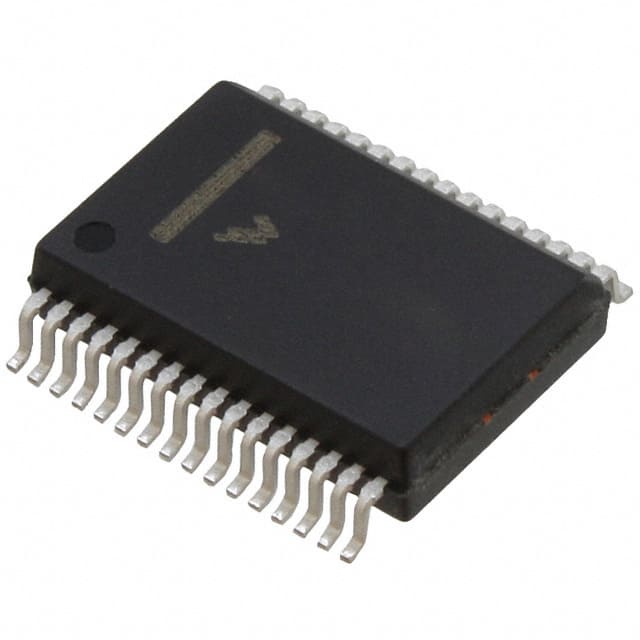
- Part No.:
- MCZ33993EWR2
- Manufacturer:
- NXP Semiconductors
- Category:
- Specialized
- Package:
- 32-BSSOP (0.295", 7.50mm Width)
- Datasheet:
-
 MCZ33993EWR2.pdf
- Description:
- IC INTERFACE SPECIALIZED 32SOIC
- Quantity:
- Payment:

- Shipping:

Inventory:2,999
Please send an inquiry. Send us your inquiry, and we will respond immediately.
Product details
Overview
MCZ33993EWR2 from NXP Semiconductors (formerly Freescale) is a 22-channel automotive-grade switch detection interface IC with integrated analog multiplexer, SPI serial interface, and ultra-low-power sleep mode. It detects open/closed states of up to 8 programmable (SP0–SP7) and 14 dedicated switch-to-ground (SG0–SG13) inputs, delivers status via 24-bit SPI, and provides buffered analog output on AMUX. Designed for vehicle body control modules requiring robust contact monitoring under battery voltage transients.
For engineers reviewing the MCZ33993EWR2 datasheet, MCZ33993EWR2 pinout, MCZ33993EWR2 application, or MCZ33993EWR2 equivalent, key selection criteria include VPWR operating range (5.5–26 V), dual wetting current options (2.0 mA / 16 mA), 100 μA typical VPWR standby current in Sleep mode, SPI-compatible 3.3/5.0 V logic interface, and integrated wake-up capability via WAKE/INT pins.
Technical Context
The MCZ33993EWR2 implements a dual-mode architecture: Normal mode enables full SPI register programming (wetting current, wake-up bits, analog channel select) and active switch monitoring with pull-up/pull-down current sourcing/sinking; Sleep mode disables SPI communication while maintaining periodic scan (100–300 μs per channel) and wake-up responsiveness via WAKE, INT, or CS edges. Its internal 4.0 V comparator threshold and ±14 V to 40 V input tolerance ensure reliable operation across automotive load-dump and reverse-battery conditions.
Switch inputs are partitioned into two groups: SP0–SP7 support software-configurable switch-to-battery or switch-to-ground polarity, while SG0–SG13 are fixed switch-to-ground only. All 22 inputs feed a shared 22:1 analog multiplexer, with offset voltage ≤ ±10 mV and sink/source capability of 250 μA on AMUX - enabling direct MCU ADC sampling without external signal conditioning.
Key Specifications
| Parameter | Value and Actual Design Meaning |
|---|---|
| VPWR Supply Range | 5.5 V to 26 V - supports full automotive battery range including cold-crank (5.5 V) and load-dump (26 V) events without external regulation. |
| VPWR Standby Current | 100 μA typical - enables >1-year battery life in always-on vehicle modules (e.g., door handle sensors, keyless entry receivers). |
| Switch Input Count | 22 total: 8 programmable (SP0–SP7) + 14 fixed switch-to-ground (SG0–SG13) - eliminates need for discrete resistor networks and diode protection. |
| Wetting Current Options | 16 mA or 2.0 mA - prevents contact oxidation during closure; 16 mA sustains for 20 ms then auto-reduces to 2.0 mA for power efficiency. |
| SPI Interface | 3.3 V / 5.0 V compatible, 6 MHz max clock - interoperates directly with common automotive MCUs (e.g., S32K, RH850, TC3xx) without level shifters. |
| AMUX Output Accuracy | ±10 mV offset, ±2.0 μA input offset current - allows precise analog sensing of potentiometers, thermistors, or resistive position sensors. |
| Operating Temperature | -40°C to +125°C case temperature - qualified for under-hood and interior automotive environments per AEC-Q100 Grade 1. |
Pinout & Package
MCZ33993EWR2 is housed in a 32-pin wide-body SOIC (SOICW) package, measuring 13.1 mm × 10.4 mm × 2.65 mm, with 1.27 mm pitch and Pb-free (EW suffix) finish compliant with JEDEC J-STD-020C reflow profiles.
| Pin/Terminal | Circuit Role | Design Meaning |
|---|---|---|
| GND (Pin 1) | Common reference | Single ground return for logic, analog, and switch-to-battery inputs - requires low-impedance PCB plane to minimize noise coupling. |
| SI (Pin 2) | SPI data input | Accepts 24-bit command words (e.g., Settings, Wake-Up/Interrupt, Metallic) from MCU; latched on falling SCLK edge. |
| SCLK (Pin 3) | SPI clock input | Drives internal shift register; rising edge clocks SO data out, falling edge latches SI data - must be low during CS transitions. |
| CS (Pin 4) | SPI chip select | Active-low enable; falling edge latches switch state and enables SO driver; rising edge resets INT and disables SO (tri-state). |
| SP0–SP7 (Pins 5–8, 25–28) | Programmable switch inputs | Configurable as switch-to-battery or switch-to-ground via SPI register; each includes 4.0 V comparator and selectable wetting current. |
| SG0–SG13 (Pins 9–15, 18–24) | Fixed switch-to-ground inputs | Dedicated ground-referenced inputs with identical 4.0 V threshold and wetting current control - no polarity configuration required. |
| VPWR (Pin 16) | Battery supply input | Primary power source for all wetting/sustain currents and internal logic; requires external reverse-battery and transient voltage suppression. |
| WAKE (Pin 17) | Open-drain wake-up output | Pulled high internally to 5.0 V; falls to wake system power supply - used to enable external LDOs or DC-DC converters during Sleep-to-Normal transition. |
| INT (Pin 29) | Open-drain interrupt output | Asserted low on switch state change (if enabled); latched on CS falling edge - signals MCU to read updated status via SPI. |
| AMUX (Pin 30) | Analog multiplexer output | Buffered analog voltage from selected SP/SG input; drives MCU ADC directly with <10 mV error - no external op-amp needed. |
| VDD (Pin 31) | Logic supply input | Sets SPI I/O voltage levels (3.3/5.0 V), powers SO driver and internal pull-ups on CS/INT - can be removed to reduce quiescent current in Sleep mode. |
| SO (Pin 32) | SPI data output | 24-bit status word (switch states, INT flag, thermal flag); tri-stated when CS high - avoids bus contention in multi-device SPI daisy chains. |
Key Features
| Feature | Design Value |
|---|---|
| Ultra-low Sleep Current | 100 μA VPWR / 20 μA VDD typical - extends battery life in always-on vehicle systems such as smart entry, seat position memory, or ambient lighting controls. |
| Configurable Wetting Current | Software-selectable 2.0 mA or 16 mA per channel with 20 ms timer - prevents contact corrosion without continuous high-current draw. |
| Integrated Analog Multiplexer | 22:1 analog mux with buffered AMUX output and ≤ ±10 mV offset - enables direct resistive sensor interfacing (e.g., HVAC blend door, pedal position) without external signal conditioning. |
| Robust Input Protection | -14 V to +40 V switch input range with internal clamping - withstands automotive reverse-battery, load-dump, and jump-start conditions without external TVS diodes. |
| Wake-Up Flexibility | Three independent wake sources: WAKE pin edge, INT pin edge (with VDD applied), or CS falling edge - ensures reliable system wakeup from any user interaction. |
Applications
| Body Control Module (BCM) | Smart Entry System |
|---|---|
|
Use Scenario: Monitoring door ajar, trunk release, hood open, and seat belt buckle switches in modern vehicle BCMs. IC Role / Device Role: Centralized switch interface replacing 22 discrete comparators, pull-up resistors, and protection diodes. Use Value: Reduces BOM count by >40 components, cuts PCB area by 35%, and enables unified SPI-based diagnostics and calibration. |
Use Scenario: Detecting proximity button presses and mechanical key fob insertion in passive keyless entry (PKE) receivers. IC Role / Device Role: Low-power wake-up controller that initiates RF handshake only upon valid switch activation. Use Value: Achieves <100 μA system standby current while maintaining sub-100 ms response time to user input. |
| Seat Position Memory | HVAC Blend Door Control |
|
Use Scenario: Reading multi-turn potentiometer wiper voltage and limit switch status for electric seat position storage and recall. IC Role / Device Role: Dual-function interface: digital switch detection (end-stop) + analog multiplexing (potentiometer wiper). Use Value: Eliminates separate ADC channel and discrete switch circuitry - single IC handles both functions with <10 mV analog accuracy. |
Use Scenario: Monitoring rotary encoder pulses and microswitch feedback from HVAC air mix doors in climate control units. IC Role / Device Role: High-voltage tolerant switch monitor with built-in wetting current to prevent contact failure in humid cabin environments. Use Value: Ensures reliable operation over 10+ year vehicle lifetime despite repeated cycling and condensation exposure. |
Equivalent & Alternatives
The following parts are listed as comparable options for similar switch detection interface applications.
| Alternative Part | Technical Difference | Application Difference | Selection Advice |
|---|---|---|---|
| MC33996EKR2 | 24-channel variant with enhanced ESD (±8 kV HBM), extended VPWR range (4.5–40 V), and integrated watchdog timer - no analog mux output. | Preferred for new designs requiring higher ESD immunity and broader battery voltage coverage; unsuitable where analog sensor reading is required. | Select MC33996EKR2 when upgrading legacy MCZ33993EWR2 designs needing improved robustness and no analog mux dependency. |
| TPIC2810PWP | 10-channel high-side switch monitor with 12-bit ADC, no SPI interface - uses parallel 8-bit bus and proprietary command protocol. | Targets industrial PLC I/O modules rather than automotive; lacks wake-up features and automotive temp grade (-40°C to +85°C only). | Choose TPIC2810PWP only for non-automotive applications where parallel interface and integrated ADC outweigh SPI compatibility and AEC-Q100 compliance needs. |
Compared with MC33996EKR2 and TPIC2810PWP, the MCZ33993EWR2 uniquely balances 22-channel switch detection, integrated analog multiplexing, ultra-low sleep current, and full AEC-Q100 qualification - making it the optimal choice for cost-sensitive, space-constrained automotive body electronics where analog sensor integration is essential.
Availability
MCZ33993EWR2 is available at Aetrix Electronics and suitable for automotive body control modules, smart entry systems, seat position memory units, and HVAC control panels requiring stable component supply across long production lifecycles.
Supply support for MCZ33993EWR2 includes scheduled delivery planning, volume procurement assistance, BOM continuity management, traceable sourcing, and lifecycle availability coordination for OEM customers, industrial embedded developers, connected-device designers, and electronics production programs.
Manufacturer
NXP Semiconductors is a global semiconductor leader focused on automotive, industrial, and IoT applications, with deep expertise in automotive electronics and AEC-Q100-qualified mixed-signal solutions.
The MCZ33993EWR2 belongs to NXP's legacy Freescale analog interface product line, specifically engineered for automotive body electronics to consolidate discrete switch monitoring functions into a single SPI-accessible IC with integrated analog sensing capability.
FAQ
What is the maximum VPWR voltage the MCZ33993EWR2 can withstand?
The MCZ33993EWR2 supports a maximum VPWR voltage of 50 V per absolute maximum ratings, though functional operation is specified from 5.5 V to 26 V. This 50 V rating enables robust handling of automotive load-dump transients without external clamping, provided external reverse-battery protection is implemented as recommended in the datasheet. The MCZ33993EWR2 maintains switch detection integrity throughout this extended range.
Does the MCZ33993EWR2 support both 3.3 V and 5.0 V SPI interfaces?
Yes, the MCZ33993EWR2 supports both 3.3 V and 5.0 V SPI logic levels. Its VDD pin sets the output voltage level for the SO driver and internal pull-ups on CS and INT pins, while SI, SCLK, and CS inputs tolerate 0.8 V to 2.2 V thresholds - ensuring interoperability with either 3.3 V or 5.0 V microcontrollers without level-shifting circuitry. This dual-voltage compatibility is confirmed in the Static Electrical Characteristics table of the MCZ33993EWR2 datasheet.
How does the MCZ33993EWR2 handle switch contact oxidation prevention?
The MCZ33993EWR2 prevents switch contact oxidation using programmable wetting current: users select either 2.0 mA or 16 mA per channel via the Metallic Command register. When 16 mA is selected, the current is applied for 20 ms upon switch closure (via internal timer), then automatically reduces to 2.0 mA for sustained operation. This pulsed high-current burst disrupts oxide film formation while minimizing average power consumption - a core design feature of the MCZ33993EWR2.
Can the MCZ33993EWR2 read analog sensor voltages?
Yes, the MCZ33993EWR2 includes a 22:1 analog multiplexer with buffered AMUX output pin. Any of the 22 switch inputs (SP0–SP7 or SG0–SG13) can be selected via the Analog Command register to route its voltage to AMUX. The output exhibits ≤ ±10 mV offset and supports 250 μA sink/source - enabling direct connection to an MCU's ADC for resistive sensor reading (e.g., potentiometers, thermistors) without external amplification. This analog capability is integral to the MCZ33993EWR2's dual digital/analog functionality.
What wake-up sources are available in Sleep mode for the MCZ33993EWR2?
In Sleep mode, the MCZ33993EWR2 supports three independent wake-up sources: (1) falling edge on the WAKE pin, (2) falling edge on the INT pin (when VDD is applied), and (3) falling edge on the CS pin (when VDD is applied). Each source triggers immediate transition to Normal mode, restoring full SPI access and switch monitoring. This multi-source flexibility ensures reliable system wakeup regardless of whether the event originates from a local switch, remote module interrupt, or diagnostic host command - a defining behavior of the MCZ33993EWR2.
MCZ33993EWR2 Specifications
- Product attributes
- Attribute value
- Manufacturer:
- NXP Semiconductors
- Series:
- -
- Package/Case:
- 32-BSSOP (0.295", 7.50mm Width)
- Packaging:
- Tape & Reel (TR)
- Product Status:
- Obsolete
- Applications:
- -
- Interface:
- SPI
- Voltage - Supply:
- 5.5V ~ 26V
- Supplier Device Package:
- 32-SOIC
- Grade:
- -
- Qualification:
- -
- Mounting Type:
- Surface Mount
MCZ33993EWR2 FAQ
1.How can I place an order for MCZ33993EWR2 through Aetrix?
Please submit a Request for Quotation (RFQ) for MCZ33993EWR2 on Aetrix. Our sales agent will provide a competitive quotation and guide you through the order confirmation once you accept the terms.
2.Are the price and stock information for MCZ33993EWR2 reliable?
The price and inventory of MCZ33993EWR2 are updated periodically and may fluctuate due to market conditions. Stock and pricing data are typically refreshed every 24 hours. Quotation validity for MCZ33993EWR2 is usually 5 days.
3.What payment methods are accepted for MCZ33993EWR2?
We accept Wire Transfer, PayPal, Credit Card, Western Union, MoneyGram, and Escrow for MCZ33993EWR2 transactions.
Note: Certain payment methods may incur a processing fee.
4.How is shipping managed for MCZ33993EWR2?
MCZ33993EWR2 orders can be shipped via leading logistics carriers, including DHL, UPS, FedEx, TNT, or Registered Mail.
Once your MCZ33993EWR2 order is processed, you will receive an email with the shipment details and tracking number.
Note: Tracking information may take up to 24 hours to appear. Express delivery typically takes 3–5 business days.
5.How can I obtain technical support or documentation for MCZ33993EWR2?
For technical support, including MCZ33993EWR2 datasheets, pinout diagrams, or application guidance, please contact our engineering support team. They can provide detailed documentation and assistance for your MCZ33993EWR2 requirements.
6.How does Aetrix verify that MCZ33993EWR2 is sourced from the original manufacturer or authorized distributors?
All MCZ33993EWR2 products on Aetrix are procured from qualified distributors and authorized channels. Our dedicated quality assurance team conducts strict verification, including traceability checks and, if necessary, third-party testing. This ensures that MCZ33993EWR2 meets industry standards.
7.What is the process for return or replacement of MCZ33993EWR2?
All MCZ33993EWR2 units undergo pre-shipment inspection (PSI). If there is an issue with MCZ33993EWR2, returns or replacements are accepted under the following conditions:
1.Quantity discrepancies, incorrect items, or visible external defects (such as breakage or corrosion), acknowledged by Aetrix.
2.The issue is reported within 90 days of delivery.
3.The MCZ33993EWR2 part is unused and in its original packaging.
Return procedure for MCZ33993EWR2:
1.Submit a request within 90 days.
2.Obtain a Return Material Authorization (RMA) from Aetrix.
MCZ33993EWR2 Tags

-
NVT4857UKAZ
NXP Semiconductors

-
TCA8418RTWR
Texas Instruments

-
PCA9546APWR
Texas Instruments

-
MD0100N8-G
Microchip Technology

-
PCA9548APW,118
NXP Semiconductors

-
PCA9540BDP,118
NXP Semiconductors

-
PCA9548APWR
Texas Instruments

-
PCA9546APW,118
NXP Semiconductors

-
PTN3360DBS,518
NXP Semiconductors

-
PCA9546ABS,118
NXP Semiconductors

-
PCA9518PWR
Texas Instruments

-
PCA9545APW,118
NXP Semiconductors
Tech Hub

A practical engineering guide to 3.3V and 5V logic compatibility, input thresholds, resistor dividers, translator ICs, MOSFET level shifting, I2C pull-ups, timing limits and power-sequencing risks.

The 74HC595 uses push-pull logic outputs, while the TPIC6B595 uses 50 V open-drain DMOS sinks for higher-power loads. This guide compares timing, current limits, 3.3 V interfacing, load wiring, thermal…

The 74HC595 converts serial data into eight stable parallel outputs. This guide covers pin functions, shift and storage timing, OE and MR behavior, drive-current limits, cascading, voltage compatibilit…

A technical comparison of level-sensitive latches and edge-triggered flip-flops, covering timing windows, setup and hold limits, master–slave operation, time borrowing, race-through, HDL inference and…

A D latch stores one bit while Enable controls when data can pass. This reference covers gate-level operation, truth tables, transparency, setup and hold timing, LE versus OE, common ICs and practical …

An SR latch stores one bit through cross-coupled feedback. This engineering reference covers NOR and NAND implementations, truth tables, forbidden-state recovery, gated operation, switch debouncing, fa…

Latch circuits retain one bit through feedback. This technical reference covers SR and D latches, truth tables, transparency, timing limits, latch-versus-flip-flop behavior, applications and common log…

An engineering guide to LED driver operation, constant-current and constant-voltage outputs, linear and switching topologies, dimming, IC selection, calculations, replacement compatibility, and fault c…

Operational amplifier guide covering op amp basics, feedback, ideal vs real op amps, common configurations, buffer circuits, offset, bias current, gain-bandwidth, slew rate, rail-to-rail limits and sel…

Jumper cables guide covering safe connection order, red and black clamp placement, final ground connection, cable gauge, length, clamp quality, copper vs CCA cables, jump starter comparison and battery…


