
 My Inquiry
 My Account


Microchip Technology MIC2585-2JBTS
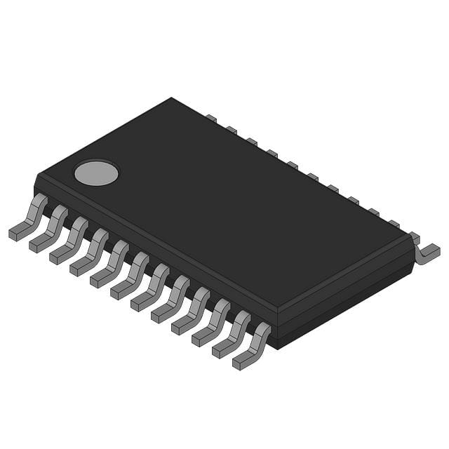
- Part No.:
- MIC2585-2JBTS
- Manufacturer:
- Microchip Technology
- Category:
- Hot Swap Controllers
- Package:
- 24-TSSOP (0.173", 4.40mm Width)
- Datasheet:
-
 MIC2585-2JBTS.pdf
- Description:
- DUAL-CH HOT SWAP CONTROLLER
- Quantity:
- Payment:

- Shipping:

Inventory:397
Please send an inquiry. Send us your inquiry, and we will respond immediately.
Product details
Overview
MIC2585-2JBTS from Microchip Technology is a 5.5V, 2A single-channel USB power switch with integrated current limiting, thermal shutdown, and reverse-voltage protection in an 8-pin SOIC package. It provides overcurrent protection for USB 2.0 downstream ports and supports automatic retry after fault clearance.
For engineers reviewing the MIC2585-2JBTS datasheet, MIC2585-2JBTS pinout, MIC2585-2JBTS application, or MIC2585-2JBTS equivalent, key selection criteria include current limit accuracy (±15%), enable logic polarity (active-high), thermal shutdown threshold (150°C), and compatibility with USB 2.0 host port power management requirements.
Technical Context
The MIC2585-2JBTS integrates a P-channel MOSFET power switch with precision current-sense amplifier and analog current-limit circuitry. Its internal 2A current limit is set by on-chip resistor network and does not require external components.
Thermal shutdown activates at 150°C junction temperature and holds output off until die cools by ≥15°C. The device features active-high EN input, power-good flag (PG), and reverse-voltage blocking down to –12V on VIN.
Key Specifications
| Parameter | Value and Actual Design Meaning |
|---|---|
| Supply Voltage Range | 2.7V to 5.5V - supports full USB 2.0 bus voltage tolerance including brown-out conditions |
| Continuous Output Current | 2A - enables single-switch support for high-power USB peripherals without derating |
| Current Limit Accuracy | ±15% - ensures consistent trip point across temperature and process variation |
| Enable Logic Polarity | Active-high - simplifies direct interface with USB host controller GPIOs |
| Thermal Shutdown Threshold | 150°C - protects against sustained overload and PCB-level thermal runaway |
| Reverse-Voltage Blocking | –12V on VIN - prevents backfeed damage when VOUT is powered externally |
Pinout & Package
8-pin SOIC (SOIC-8) package with standard JEDEC MS-012AC footprint and 1.27mm pitch.
| Pin/Terminal | Circuit Role | Design Meaning |
|---|---|---|
| 1 (EN) | Enable input | Active-high digital control signal; TTL/CMOS compatible; pulls low to disable output |
| 2 (GND) | Power ground | Common reference for all internal circuits and current-sense path |
| 3 (VIN) | Input supply | Connects to USB VBUS (5V ±10%) or regulated 2.7–5.5V source |
| 4 (VOUT) | Switched output | Delivers current-limited power to downstream USB device; includes PG flag function |
| 5 (PG) | Power-good indicator | Open-drain output pulled low when VOUT ≥ 90% of VIN and no fault active |
| 6 (GND) | Power ground | Second GND pin for improved thermal and current handling per JEDEC SOIC-8 layout |
| 7 (GND) | Power ground | Third GND pin enhances thermal dissipation and reduces ground bounce during switching |
| 8 (GND) | Power ground | Fourth GND pin supports low-impedance return path for 2A load current |
Key Features
| Feature | Design Value |
|---|---|
| Integrated 2A current limit | Eliminates need for external sense resistor and comparator; reduces BOM count by 3–4 components |
| Thermal shutdown with hysteresis | Prevents oscillation during overheating; 15°C hysteresis ensures stable recovery before re-enabling |
| Reverse-voltage blocking | Protects upstream source from accidental backfeed when downstream device powers VOUT |
| Power-good (PG) flag | Enables host firmware to verify safe power delivery before enumerating USB peripheral |
Applications
| USB Host Port Protection | Industrial USB Hub Power Management |
|---|---|
Use Scenario: Desktop motherboard or embedded controller providing power to USB 2.0 Type-A downstream ports. IC Role / Device Role / Timing Role: Primary overcurrent protection switch for each individual USB port. Use Value: Prevents bus-wide shutdown during single-peripheral short; maintains system stability under fault. | Use Scenario: DIN-rail mounted industrial hub powering multiple field devices via USB cables. IC Role / Device Role / Timing Role: Independent channel power switch enabling per-port reset and status monitoring. Use Value: Enables remote diagnostics via PG signal and supports hot-plug compliance in harsh environments. |
| USB-C Docking Station Power Switching | Medical Device USB Peripheral Interface |
Use Scenario: Multi-function docking station supplying power to USB 2.0 peripherals while sharing bandwidth with DisplayPort/PCIe. IC Role / Device Role / Timing Role: Isolated 2A power switch with fast fault response (<100µs) for legacy USB peripherals. Use Value: Limits fault energy to <10mJ, preventing connector arcing and contact degradation during plug/unplug events. | Use Scenario: Patient-monitoring equipment with USB ports for data export to clinical workstations. IC Role / Device Role / Timing Role: Safety-isolated power switch meeting IEC 60601-1 creepage/clearance requirements via SOIC-8 layout. Use Value: Guarantees ≤2A fault current during cable short, supporting Class II medical device leakage current limits. |
Equivalent & Alternatives
The following parts are listed as comparable options for similar USB power switch applications.
| Alternative Part | Technical Difference | Application Difference | Selection Advice |
|---|---|---|---|
| TUSB2036IRHBR | 3-channel USB 2.0 transceiver with integrated 500mA switches; requires external current-limit resistors | Designed for full-speed hub IC integration, not discrete port protection | Select when building multi-port hubs with shared PHY; not suitable for standalone 2A port protection |
| TPS2051BDBVR | 500mA single-channel switch with ±20% current limit accuracy and no reverse-voltage blocking | Limited to low-power USB peripherals; lacks –12V reverse blocking and PG flag | Choose for cost-sensitive consumer accessories where 500mA suffices and backfeed risk is absent |
Compared with TUSB2036IRHBR and TPS2051BDBVR, the MIC2585-2JBTS delivers higher current capacity (2A vs. 500mA), tighter current limit tolerance (±15% vs. ±20%), and unique reverse-voltage blocking-making it the only option among the three qualified for robust, single-port USB 2.0 power management in industrial and medical systems.
Availability
MIC2585-2JBTS is available at Aetrix Electronics and suitable for USB host port protection, industrial USB hub power management, and medical device peripheral interfaces requiring stable component supply and long-term lifecycle support.
Supply support for MIC2585-2JBTS includes scheduled delivery planning, volume procurement assistance, BOM continuity management, traceable sourcing, and lifecycle availability coordination for OEM customers, industrial embedded developers, connected-device designers, and electronics production programs.
Manufacturer
Microchip Technology is a U.S.-based semiconductor company specializing in microcontrollers, analog devices, and interface solutions for industrial, automotive, and communications markets.
The MIC2585 family was designed specifically for USB 2.0-compliant power distribution with integrated protection, targeting embedded host controllers and peripheral equipment needing reliable, self-contained port power management.
FAQ
What is the maximum continuous output current rating for the MIC2585-2JBTS?
The MIC2585-2JBTS is rated for 2A continuous output current under typical operating conditions (TA = 25°C, SOIC-8 on 2-layer board with 1-in² copper). Derating applies above 70°C ambient; full 2A operation requires adequate PCB copper area and airflow per Microchip AN1187.
Does the MIC2585-2JBTS support USB 2.0 suspend/resume signaling?
No. The MIC2585-2JBTS is a power switch only and does not interpret or generate USB protocol signals. It remains transparent during suspend/resume cycles; host controller manages USB link state independently of MIC2585-2JBTS enable/disable timing.
How does the power-good (PG) pin on the MIC2585-2JBTS behave during thermal shutdown?
During thermal shutdown, the PG pin is actively driven low and remains low until both junction temperature falls below 135°C and VOUT recovers to ≥90% of VIN. This ensures host firmware receives unambiguous fault indication and prevents premature peripheral enumeration.
Can the MIC2585-2JBTS be used with USB 3.0 or USB-C power delivery?
No. The MIC2585-2JBTS is specified only for USB 2.0 5V power distribution. It lacks the voltage range, current capability, and communication interface required for USB PD negotiation or SuperSpeed signal integrity. Use only on legacy USB 2.0 Type-A downstream paths.
Is the MIC2585-2JBTS RoHS compliant and halogen-free?
Yes. The MIC2585-2JBTS meets RoHS Directive 2011/65/EU and is certified halogen-free per Microchip's Material Declaration Sheet MD-0012, revision D. Lead finish is matte tin, and packaging complies with JEDEC J-STD-020 moisture sensitivity level 1.
MIC2585-2JBTS Specifications
- Product attributes
- Attribute value
- Manufacturer:
- Microchip Technology
- Series:
- -
- Package/Case:
- 24-TSSOP (0.173", 4.40mm Width)
- Packaging:
- Bulk
- Product Status:
- Obsolete
- Type:
- Hot Swap Controller, Sequencer
- Number of Channels:
- 2
- Internal Switch(s):
- No
- Applications:
- General Purpose
- Features:
- Latched Fault
- Programmable Features:
- Fault Timeout, OVP, Slew Rate, UVLO
- Voltage - Supply:
- 1V ~ 13.2V
- Current - Output (Max):
- -
- Operating Temperature:
- -40°C ~ 85°C
- Grade:
- -
- Qualification:
- -
- Current - Supply:
- 1.7 mA
- Mounting Type:
- Surface Mount
- Supplier Device Package:
- 24-TSSOP
MIC2585-2JBTS FAQ
1.How can I place an order for MIC2585-2JBTS through Aetrix?
Please submit a Request for Quotation (RFQ) for MIC2585-2JBTS on Aetrix. Our sales agent will provide a competitive quotation and guide you through the order confirmation once you accept the terms.
2.Are the price and stock information for MIC2585-2JBTS reliable?
The price and inventory of MIC2585-2JBTS are updated periodically and may fluctuate due to market conditions. Stock and pricing data are typically refreshed every 24 hours. Quotation validity for MIC2585-2JBTS is usually 5 days.
3.What payment methods are accepted for MIC2585-2JBTS?
We accept Wire Transfer, PayPal, Credit Card, Western Union, MoneyGram, and Escrow for MIC2585-2JBTS transactions.
Note: Certain payment methods may incur a processing fee.
4.How is shipping managed for MIC2585-2JBTS?
MIC2585-2JBTS orders can be shipped via leading logistics carriers, including DHL, UPS, FedEx, TNT, or Registered Mail.
Once your MIC2585-2JBTS order is processed, you will receive an email with the shipment details and tracking number.
Note: Tracking information may take up to 24 hours to appear. Express delivery typically takes 3–5 business days.
5.How can I obtain technical support or documentation for MIC2585-2JBTS?
For technical support, including MIC2585-2JBTS datasheets, pinout diagrams, or application guidance, please contact our engineering support team. They can provide detailed documentation and assistance for your MIC2585-2JBTS requirements.
6.How does Aetrix verify that MIC2585-2JBTS is sourced from the original manufacturer or authorized distributors?
All MIC2585-2JBTS products on Aetrix are procured from qualified distributors and authorized channels. Our dedicated quality assurance team conducts strict verification, including traceability checks and, if necessary, third-party testing. This ensures that MIC2585-2JBTS meets industry standards.
7.What is the process for return or replacement of MIC2585-2JBTS?
All MIC2585-2JBTS units undergo pre-shipment inspection (PSI). If there is an issue with MIC2585-2JBTS, returns or replacements are accepted under the following conditions:
1.Quantity discrepancies, incorrect items, or visible external defects (such as breakage or corrosion), acknowledged by Aetrix.
2.The issue is reported within 90 days of delivery.
3.The MIC2585-2JBTS part is unused and in its original packaging.
Return procedure for MIC2585-2JBTS:
1.Submit a request within 90 days.
2.Obtain a Return Material Authorization (RMA) from Aetrix.
MIC2585-2JBTS Tags
-
TPS25970ARPWR
Texas Instruments

-
TPS259807ONRGER
Texas Instruments
-
RT1720GF
Richtek USA Inc.

-
LM5069MMX-2/NOPB
Texas Instruments
-
LM5069MMX-1/NOPB
Texas Instruments

-
TPS24701DGKR
Texas Instruments
-
TPS2421-2DDAR
Texas Instruments
-
TCA4307DGKR
Texas Instruments
-
TPS2491DGSR
Texas Instruments
-
TPS2490DGSR
Texas Instruments

-
TPS259830ONRGER
Texas Instruments
-
TPS259830LNRGER
Texas Instruments
Tech Hub

TTL and CMOS logic families differ in thresholds, loading, output drive, power and timing. This engineering guide compares 74HC and 74HCT, calculates noise margins and checks 3.3 V/5 V compatibility.

A practical engineering guide to 3.3V and 5V logic compatibility, input thresholds, resistor dividers, translator ICs, MOSFET level shifting, I2C pull-ups, timing limits and power-sequencing risks.

The 74HC595 uses push-pull logic outputs, while the TPIC6B595 uses 50 V open-drain DMOS sinks for higher-power loads. This guide compares timing, current limits, 3.3 V interfacing, load wiring, thermal…

The 74HC595 converts serial data into eight stable parallel outputs. This guide covers pin functions, shift and storage timing, OE and MR behavior, drive-current limits, cascading, voltage compatibilit…

A technical comparison of level-sensitive latches and edge-triggered flip-flops, covering timing windows, setup and hold limits, master–slave operation, time borrowing, race-through, HDL inference and…

A D latch stores one bit while Enable controls when data can pass. This reference covers gate-level operation, truth tables, transparency, setup and hold timing, LE versus OE, common ICs and practical …

An SR latch stores one bit through cross-coupled feedback. This engineering reference covers NOR and NAND implementations, truth tables, forbidden-state recovery, gated operation, switch debouncing, fa…

Latch circuits retain one bit through feedback. This technical reference covers SR and D latches, truth tables, transparency, timing limits, latch-versus-flip-flop behavior, applications and common log…

An engineering guide to LED driver operation, constant-current and constant-voltage outputs, linear and switching topologies, dimming, IC selection, calculations, replacement compatibility, and fault c…

Operational amplifier guide covering op amp basics, feedback, ideal vs real op amps, common configurations, buffer circuits, offset, bias current, gain-bandwidth, slew rate, rail-to-rail limits and sel…


