
 My Inquiry
 My Account


Microchip Technology MIC2870YFT-TR
- Part No.:
- MIC2870YFT-TR
- Manufacturer:
- Microchip Technology
- Category:
- LED Drivers
- Package:
- 16-UFQFN Exposed Pad
- Datasheet:
-
 MIC2870YFT-TR.pdf
- Description:
- IC LED DRV RGLTR I2C 1.5A 16TQFN
- Quantity:
- Payment:

- Shipping:

Inventory:4,652
Please send an inquiry. Send us your inquiry, and we will respond immediately.
Product details
Overview
MIC2870YFT-TR from Microchip Technology is a 1.5A synchronous boost flash LED driver IC for dual-channel WLED camera illumination, operating from 2.7V to 5.0V input, delivering up to 750 mA per channel in Flash mode or 1.5A in single-LED configuration, with 2 MHz adaptive switching and I²C (up to 3.4 MHz) or pin-based control - deployed in smartphone camera modules for auto-focus assist and image capture.
For engineers reviewing the MIC2870YFT-TR datasheet, MIC2870YFT-TR pinout, MIC2870YFT-TR application, or MIC2870YFT-TR equivalent, this page delivers verified functional architecture, validated thermal and protection behavior, confirmed dual-mode current programming via FRSET/TRSET, and real-world torch/flash timing constraints - all aligned to DS20006078A.
Technical Context
The MIC2870YFT-TR integrates a 2 MHz synchronous boost converter with internal NMOS/PMOS power switches (RON ≤ 80 mΩ), supporting both Flash (≤1.25 s safety timeout) and Torch modes. Its dual-current-sink architecture provides automatic current matching (±5%) between LED1 and LED2 when both channels are active.
Control is implemented via either hardware pins (FEN/TEN/FI) or high-speed I²C interface (3.4 MHz max), with independent current programming through FRSET (Flash, 0–750 mA/ch) and TRSET (Torch, 0–187.5 mA/ch) resistors. Protection includes OVP (5.38 V), overtemperature shutdown (160 °C), LED open/short detection, and true load disconnect.
Key Specifications
| Parameter | Value and Actual Design Meaning |
|---|---|
| Max Flash Current | 750 mA per channel (1.5 A total in single-LED mode); enables high-intensity burst illumination for image capture. |
| Input Voltage Range | 2.7 V to 5.0 V; compatible with single-cell Li-ion/Li-poly battery systems without external regulation. |
| Switching Frequency | 2.0 MHz (1.8–2.2 MHz range); allows use of compact 1 µH inductor and 2.2 µF output capacitor. |
| Shutdown Current | 0.6 µA typical; minimizes battery drain during standby in portable devices. |
| I²C Interface Speed | Up to 3.4 MHz; supports fast register writes for auto-focus synchronization and dynamic brightness adjustment. |
| Overvoltage Protection | 5.38 V threshold with 60 mV hysteresis; prevents damage during LED open-circuit fault conditions. |
| Thermal Shutdown | 160 °C junction temperature with 25 °C hysteresis; ensures safe operation under sustained high-current loads. |
Pinout & Package
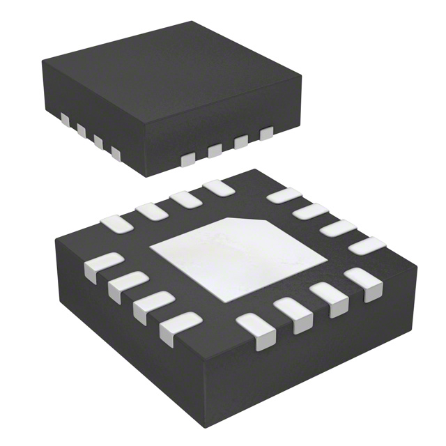
Package: 16-pin, 2 mm × 2 mm TQFN with exposed thermal pad (ePAD), rated for –40°C to +125°C junction temperature.
| Pin/Terminal | Circuit Role | Design Meaning |
|---|---|---|
| SCL | I²C clock input | High-speed (≤3.4 MHz) clock line requiring 4.7 kΩ pull-up; synchronizes register access for Flash/Torch control. |
| VIN | Main power input | 2.7–5.0 V supply; requires ≥4.7 µF low-ESR ceramic capacitor to PGND for stable boost operation. |
| FEN | Hardware Flash enable | Rising-edge triggered; initiates Flash mode and starts 1.25 s safety timer; internally pulled down if floating. |
| FI | Flash inhibit control | Pulled high to reduce LED current from Flash to Torch level during GSM pulse intervals, minimizing battery droop. |
| FRSET | Flash current programming | Resistor-to-AGND sets max Flash current (e.g., 10 kΩ = 750 mA/ch); grounded for default setting. |
| AGND | Analog reference ground | Reference for FRSET/TRSET bias; must be connected to PGND at single point to avoid noise coupling. |
| PGND | Power ground | Return path for boost switch currents and LED sink paths; connects internally to ePAD for thermal dissipation. |
| TRSET | Torch current programming | Resistor-to-AGND sets max Torch current (e.g., 10 kΩ = 187.5 mA/ch); grounded for default setting. |
| LED1 / LED2 | Current sink outputs | Cathode connections for dual WLEDs; automatically matched within ±5% when both channels active. |
| TEN | Hardware Torch enable | Rising-edge triggered; activates Torch mode; internally pulled down if floating. |
| OUT | Boost output node | Drives LED anodes; requires ≥2.2 µF low-ESR ceramic capacitor to PGND for ripple suppression. |
| EN | Global IC enable | High = Standby; low >1 s = full shutdown; also controllable via I²C Master Control register. |
| SW | Switch node | Connects to inductor; carries high di/dt switching current; must be routed away from sensitive analog traces. |
| SDA | I²C data I/O | Open-drain bidirectional line requiring 4.7 kΩ pull-up; supports read/write to Flash/Torch/Status registers. |
| ePAD | Exposed thermal pad | Internally tied to PGND; must be soldered to PCB ground plane for thermal performance and EMI reduction. |
Key Features
| Feature | Design Value |
|---|---|
| Configurable dual-mode operation | Independent Flash (≤1.25 s) and Torch modes, each programmable via dedicated pins (FEN/TEN) or I²C registers (01h/02h). |
| True load disconnect | Internal NMOS discharge path (RDCHG = 160 Ω) actively sinks OUT voltage to near zero during shutdown, eliminating residual LED glow. |
| Flash time-out protection | Hardwired 1.25 s safety timer prevents thermal runaway; non-adjustable but guaranteed across –40°C to +125°C. |
| GSM pulse synchronization | FI pin dynamically scales Flash current to Torch level during RF transmission bursts, reducing peak battery current by up to 75%. |
| LED fault protection | Dual independent detectors: open-circuit (25 mV threshold, 65 µs blanking) and short-circuit (600 mV threshold, 30 µs blanking), with 100 ms retry cycles. |
Applications
| Smartphone Camera Flash | Auto-Focus Assist Illumination |
|---|---|
Use Scenario: High-intensity, sub-second illumination during still-image capture in low-light conditions. IC Role / Device Role / Timing Role: Dual-channel flash driver delivering synchronized 750 mA per LED with 1.25 s hard safety timeout. Use Value: Enables consistent exposure in <100 ms shutter windows while preventing thermal shutdown during rapid burst capture. |
Use Scenario: Continuous low-brightness illumination during phase-detection or contrast-detection auto-focus sequence. IC Role / Device Role / Timing Role: Torch-mode current sink (programmable up to 187.5 mA/ch) with I²C-adjustable brightness and no time limit. Use Value: Provides stable, flicker-free light for focus algorithms without triggering flash safety timer or exceeding battery peak current limits. |
| White Balance Calibration Light | Video Torch for Mobile Recording |
Use Scenario: Precise color-temperature-matched illumination during camera white balance calibration routines. IC Role / Device Role / Timing Role: Dual-channel current-matched sink (±5% matching) with independent FRSET/TRSET resistor programming for spectral consistency. Use Value: Ensures identical forward voltage drop and thermal drift across both LEDs, critical for accurate RGB sensor response calibration. |
Use Scenario: Steady, adjustable brightness lighting during handheld video recording in dim environments. IC Role / Device Role / Timing Role: Torch-mode driver with 0–187.5 mA/ch analog current control via TRSET resistor and digital fine-tuning via I²C register. Use Value: Delivers smooth brightness ramping and stable luminance over extended durations without thermal throttling or audible coil whine. |
Equivalent & Alternatives
The following parts are listed as comparable options for similar flash LED driver applications.
| Alternative Part | Technical Difference | Application Difference | Selection Advice |
|---|---|---|---|
| RT8542GSP | Single-channel, 1.2 A max; no I²C interface; uses PWM-only brightness control. | Lacks dual-channel matching and Flash/Torch mode separation; limited to basic torch-only or discrete flash timing. | Select when cost-sensitive, single-LED designs require minimal feature set and no firmware integration. |
| ISL97693IRTZ-T7A | 3-channel, 400 mA/ch; supports analog + PWM dimming; no Flash safety timer or FI pin. | Designed for multi-LED display backlighting; lacks GSM-sync capability and fixed 1.25 s Flash timeout. | Select for triple-LED arrays where independent channel control outweighs camera-specific protections. |
Compared with RT8542GSP and ISL97693IRTZ-T7A, the MIC2870YFT-TR uniquely combines dual-channel current matching, hardware-triggered Flash/Torch modes with safety timers, and GSM-synchronized Flash Inhibit - making it the only option qualified for high-reliability smartphone camera flash subsystems requiring both burst intensity and sustained torch stability.
Availability
MIC2870YFT-TR is available at Aetrix Electronics and suitable for smartphone camera modules, mobile handset imaging subsystems, and portable digital camera flash circuits requiring stable component supply, long-term lifecycle support, and automotive-grade thermal robustness.
Supply support for MIC2870YFT-TR includes scheduled delivery planning, volume procurement assistance, BOM continuity management, traceable sourcing, and lifecycle availability coordination for OEM customers, industrial embedded developers, connected-device designers, and electronics production programs.
Manufacturer
Microchip Technology is a U.S.-based semiconductor company specializing in microcontrollers, analog devices, and power management ICs, with broad design-in support across consumer, industrial, and automotive markets.
The MIC2870 product line targets high-efficiency, space-constrained camera flash applications in mobile handsets, emphasizing integrated protection, dual-mode flexibility, and battery-friendly low-quiescent operation.
FAQ
What is the maximum continuous current the MIC2870YFT-TR can deliver in Torch mode?
The MIC2870YFT-TR supports up to 187.5 mA per channel in Torch mode when TRSET is grounded; with external resistor programming, maximum per-channel current remains capped at 187.5 mA. Total dual-channel output is 375 mA, and the device does not enforce a time limit in Torch mode - unlike Flash mode's 1.25 s safety timeout. This makes MIC2870YFT-TR suitable for extended-duration video lighting.
Does the MIC2870YFT-TR support true load disconnect, and how is it implemented?
Yes, the MIC2870YFT-TR implements true load disconnect via an internal NMOS discharge switch (RDCHG = 160 Ω) connected between OUT and PGND. When EN is deasserted or the device enters shutdown, this switch actively pulls the OUT node to near ground, eliminating residual voltage that could cause LED afterglow or unintended biasing. This behavior is confirmed in DS20006078A Figure 2-17 and Table 1-1.
How does the Flash Inhibit (FI) function interact with I²C-controlled Flash mode on the MIC2870YFT-TR?
The FI pin remains fully functional even when Flash mode is initiated via I²C register write (address 01h). When FI is pulled high during active Flash, the MIC2870YFT-TR immediately scales both LED currents from the programmed Flash level down to the Torch level - independent of control method. This allows GSM pulse synchronization regardless of whether Flash is triggered by FEN or I²C, as specified in Section 4.10 and Figure 2-23 of DS20006078A.
What is the minimum recommended input capacitance for stable operation of the MIC2870YFT-TR?
The MIC2870YFT-TR requires a minimum 4.7 µF low-ESR ceramic capacitor from VIN to PGND, placed as close as possible to the device. A supplemental 100 nF capacitor between VIN and AGND is highly recommended to suppress high-frequency noise affecting analog circuitry. These values are specified in Section 4.1 and the Typical Application Schematic on page 2 of DS20006078A.
Can the MIC2870YFT-TR drive a single 1.5A WLED, and how is current accuracy maintained?
Yes - the MIC2870YFT-TR supports single-LED operation at up to 1.5A by connecting both LED1 and LED2 cathodes together and routing them to one LED anode via OUT. In this configuration, current accuracy is maintained at ±10% (vs. ±5% in dual-channel mode), as stated in Table 1-1 Channel Current Accuracy specification. The internal current mirrors remain active, and FRSET programming continues to set the total 1.5A output.
MIC2870YFT-TR Specifications
- Product attributes
- Attribute value
- Manufacturer:
- Microchip Technology
- Series:
- -
- Package/Case:
- 16-UFQFN Exposed Pad
- Packaging:
- Tape & Reel (TR)
- Product Status:
- Obsolete
- Type:
- DC DC Regulator
- Topology:
- Step-Up (Boost)
- Internal Switch(s):
- Yes
- Number of Outputs:
- 2
- Voltage - Supply (Min):
- 2.7V
- Voltage - Supply (Max):
- 5V
- Voltage - Output:
- 5.2V
- Current - Output / Channel:
- 1.5A (Flash)
- Frequency:
- 2MHz
- Dimming:
- I2C
- Applications:
- Camera Flash
- Operating Temperature:
- -40°C ~ 125°C (TJ)
- Grade:
- -
- Qualification:
- -
- Mounting Type:
- Surface Mount
- Supplier Device Package:
- 16-TQFN (2x2)
MIC2870YFT-TR FAQ
1.How can I place an order for MIC2870YFT-TR through Aetrix?
Please submit a Request for Quotation (RFQ) for MIC2870YFT-TR on Aetrix. Our sales agent will provide a competitive quotation and guide you through the order confirmation once you accept the terms.
2.Are the price and stock information for MIC2870YFT-TR reliable?
The price and inventory of MIC2870YFT-TR are updated periodically and may fluctuate due to market conditions. Stock and pricing data are typically refreshed every 24 hours. Quotation validity for MIC2870YFT-TR is usually 5 days.
3.What payment methods are accepted for MIC2870YFT-TR?
We accept Wire Transfer, PayPal, Credit Card, Western Union, MoneyGram, and Escrow for MIC2870YFT-TR transactions.
Note: Certain payment methods may incur a processing fee.
4.How is shipping managed for MIC2870YFT-TR?
MIC2870YFT-TR orders can be shipped via leading logistics carriers, including DHL, UPS, FedEx, TNT, or Registered Mail.
Once your MIC2870YFT-TR order is processed, you will receive an email with the shipment details and tracking number.
Note: Tracking information may take up to 24 hours to appear. Express delivery typically takes 3–5 business days.
5.How can I obtain technical support or documentation for MIC2870YFT-TR?
For technical support, including MIC2870YFT-TR datasheets, pinout diagrams, or application guidance, please contact our engineering support team. They can provide detailed documentation and assistance for your MIC2870YFT-TR requirements.
6.How does Aetrix verify that MIC2870YFT-TR is sourced from the original manufacturer or authorized distributors?
All MIC2870YFT-TR products on Aetrix are procured from qualified distributors and authorized channels. Our dedicated quality assurance team conducts strict verification, including traceability checks and, if necessary, third-party testing. This ensures that MIC2870YFT-TR meets industry standards.
7.What is the process for return or replacement of MIC2870YFT-TR?
All MIC2870YFT-TR units undergo pre-shipment inspection (PSI). If there is an issue with MIC2870YFT-TR, returns or replacements are accepted under the following conditions:
1.Quantity discrepancies, incorrect items, or visible external defects (such as breakage or corrosion), acknowledged by Aetrix.
2.The issue is reported within 90 days of delivery.
3.The MIC2870YFT-TR part is unused and in its original packaging.
Return procedure for MIC2870YFT-TR:
1.Submit a request within 90 days.
2.Obtain a Return Material Authorization (RMA) from Aetrix.
MIC2870YFT-TR Tags

-
BCR402RE6327HTSA1
Infineon Technologies

-
BCR430UXTSA2
Infineon Technologies

-
BCR420UE6433HTMA1
Infineon Technologies
-
BCR420UE6327HTSA1
Infineon Technologies
-
BCR421UE6327HTSA1
Infineon Technologies

-
LYT1604D-TL
Power Integrations

-
HV9910CLG-G
Microchip Technology

-
CL2N8-G
Microchip Technology

-
BCR420UW6-7
Diodes Incorporated
-
BCR421UW6-7
Diodes Incorporated

-
BCR420UFD-7
Diodes Incorporated
-
BCR421UFD-7
Diodes Incorporated
Tech Hub

TTL and CMOS logic families differ in thresholds, loading, output drive, power and timing. This engineering guide compares 74HC and 74HCT, calculates noise margins and checks 3.3 V/5 V compatibility.

A practical engineering guide to 3.3V and 5V logic compatibility, input thresholds, resistor dividers, translator ICs, MOSFET level shifting, I2C pull-ups, timing limits and power-sequencing risks.

The 74HC595 uses push-pull logic outputs, while the TPIC6B595 uses 50 V open-drain DMOS sinks for higher-power loads. This guide compares timing, current limits, 3.3 V interfacing, load wiring, thermal…

The 74HC595 converts serial data into eight stable parallel outputs. This guide covers pin functions, shift and storage timing, OE and MR behavior, drive-current limits, cascading, voltage compatibilit…

A technical comparison of level-sensitive latches and edge-triggered flip-flops, covering timing windows, setup and hold limits, master–slave operation, time borrowing, race-through, HDL inference and…

A D latch stores one bit while Enable controls when data can pass. This reference covers gate-level operation, truth tables, transparency, setup and hold timing, LE versus OE, common ICs and practical …

An SR latch stores one bit through cross-coupled feedback. This engineering reference covers NOR and NAND implementations, truth tables, forbidden-state recovery, gated operation, switch debouncing, fa…

Latch circuits retain one bit through feedback. This technical reference covers SR and D latches, truth tables, transparency, timing limits, latch-versus-flip-flop behavior, applications and common log…

An engineering guide to LED driver operation, constant-current and constant-voltage outputs, linear and switching topologies, dimming, IC selection, calculations, replacement compatibility, and fault c…

Operational amplifier guide covering op amp basics, feedback, ideal vs real op amps, common configurations, buffer circuits, offset, bias current, gain-bandwidth, slew rate, rail-to-rail limits and sel…


