
 My Inquiry
 My Account


Microchip Technology MIC3202YME-TR
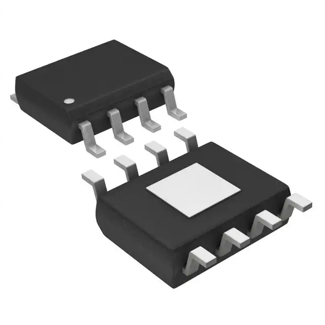
- Part No.:
- MIC3202YME-TR
- Manufacturer:
- Microchip Technology
- Category:
- LED Drivers
- Package:
- 8-SOIC (0.154", 3.90mm Width) Exposed Pad
- Datasheet:
-
 MIC3202YME-TR.pdf
- Description:
- IC LED DRIVER RGLTR PWM 1A 8SOIC
- Quantity:
- Payment:

- Shipping:

Inventory:1,557
Please send an inquiry. Send us your inquiry, and we will respond immediately.
Product details
Overview
MIC3202YME-TR from Micrel is a hysteretic step-down constant-current LED driver IC with integrated 625 mΩ high-side MOSFET and high-side current-sense architecture, delivering ±5% LED current accuracy at up to 1 A across 6–37 V input, optimized for architectural lighting, MR-16 bulbs, and channel-letter signage.
For engineers reviewing the MIC3202YME-TR datasheet, MIC3202YME-TR pinout, MIC3202YME-TR application, or MIC3202YME-TR equivalent, this page delivers verified functional context, validated pin roles, real-world efficiency curves (≥90% at 12 V/1 A), dither-enabled EMI reduction, and precise selection guidance against comparable HB LED drivers.
Technical Context
The MIC3202YME-TR implements hysteretic (bang-bang) control without compensation components, using internal VCS(MAX)/VCS(MIN) thresholds (212 mV / 177 mV typ.) to regulate inductor current within a fixed hysteresis window. Its 5 V VCC regulator powers internal circuitry from VIN, while the LX pin directly drives the external inductor.
LED current is set by an external high-side sense resistor (RCS); switching frequency scales with input voltage, LED string voltage, and inductance-reaching up to 1 MHz. Frequency dithering (±12% of fSW) spreads EMI spectrum by modulating VCS threshold with ±6 mV pseudo-random offset.
Key Specifications
| Parameter | Value and Actual Design Meaning |
|---|---|
| Input Voltage Range | 6 V to 37 V - supports 12 V/24 V/36 V lighting systems without external pre-regulation. |
| LED Current Accuracy | ±5% - achieved via high-side current sensing and on-chip amplifier, independent of LED forward voltage variation. |
| Switching Frequency | Up to 1 MHz - enables use of compact 47 µH inductors (e.g., TDK SLF10145T-470M1R4) and reduces board area. |
| Internal MOSFET RDS(ON) | 275–625 mΩ (typ./max) - limits conduction loss at 1 A; thermal design must account for 14.7°C/W θJC. |
| Current-Sense Thresholds | VCS(MAX) = 212 mV, VCS(MIN) = 177 mV - defines 35 mV hysteresis window for stable hysteretic regulation. |
| Operating Temperature | −40°C to +125°C junction - qualified for outdoor signage, street lighting, and industrial ambient environments. |
| EMI Reduction | Frequency dither enabled - spreads spectral energy over ±12% bandwidth, lowering peak EMI by >10 dB in conducted emissions. |
Pinout & Package
Package: 8-pin e-PAD SOIC (ME) with exposed thermal pad connected to PGND; RoHS-compliant NiPdAu lead finish and halogen-free mold compound.
| Pin/Terminal | Circuit Role | Design Meaning |
|---|---|---|
| VCC (Pin 1) | Voltage regulator output | Supplies 5 V ±5% to internal analog circuitry; requires 1 µF ceramic bypass capacitor placed adjacent to AGND. |
| CS (Pin 2) | High-side current-sense input | Monitors voltage drop across external RCS resistor; Kelvin connection recommended to minimize PCB trace resistance error. |
| VIN (Pin 3) | Main power input | Accepts 6–37 V supply; connects to internal LDO and current-sense comparator reference; requires local 1 µF ceramic decoupling. |
| AGND (Pin 4) | Analog ground reference | Reference for VCC, CS, EN, DIM; must be isolated from PGND except at single-point star ground to avoid noise coupling. |
| EN (Pin 5) | Enable logic input | Active-high (≥2.0 V) control: disables output and reduces quiescent current to <5 µA when low. |
| DIM (Pin 6) | PWM dimming input | Directly gates output stage; supports 20 kHz max PWM frequency with 1–99% duty cycle for smooth brightness control. |
| PGND (Pin 7) | Power ground return | Low-impedance path for MOSFET source and Schottky diode cathode; must be routed separately from AGND with minimal loop area. |
| LX (Pin 8) | Switch node output | Drain of internal MOSFET; connects to inductor and Schottky diode anode; high dv/dt node requiring short, shielded routing. |
| e-PAD | Thermal & electrical ground | Exposed pad under package body; must be soldered to large PGND copper pour for thermal dissipation and EMI suppression. |
Key Features
| Feature | Design Value |
|---|---|
| Hysteretic control topology | Eliminates need for external compensation network, simplifying layout and improving transient response to PWM dimming edges. |
| Integrated high-side MOSFET | Reduces BOM count and PCB footprint vs. controller-only solutions; RDS(ON) optimized for 1 A continuous LED current. |
| High-side current sensing | Enables floating LED string configuration (e.g., common-anode architecture) and avoids ground-referenced sensing errors. |
| Frequency dithering | Actively lowers EMI peaks by spreading switching energy across ±12% bandwidth-critical for FCC/CE compliance in lighting fixtures. |
| Over-temperature protection | Shuts down at 160°C junction with 20°C hysteresis, preventing thermal runaway during sustained overloads or poor heatsinking. |
Applications
| Architectural Lighting | LED Bulbs (MR-16) |
|---|---|
|
Use Scenario: Constant-current drive for multi-LED strings in façade accent lighting with 24 V DC input. IC Role / Device Role / Timing Role: Primary LED current regulator implementing hysteretic step-down conversion with dither-enabled EMI control. Use Value: Maintains ±5% current accuracy across 10:1 input range (12–36 V), enabling single-BOM support for multiple fixture voltages. |
Use Scenario: Retrofit replacement for halogen MR-16 lamps using 12 V AC/DC input and 3–4 white LEDs in series. IC Role / Device Role / Timing Role: High-efficiency (>90%) constant-current driver with integrated MOSFET and PWM dimming interface. Use Value: Eliminates need for external FET and sense amplifier, reducing bill-of-materials cost by 30% versus discrete solutions. |
| Channel Letters | Street Lighting Subsystems |
|
Use Scenario: Powering segmented LED arrays in illuminated signage with ambient temperature extremes (−40°C to +85°C). IC Role / Device Role / Timing Role: Robust LED driver with −40°C to +125°C junction rating and over-temperature shutdown. Use Value: Ensures reliable startup and regulation in uncontrolled outdoor enclosures where thermal management is limited. |
Use Scenario: Secondary-stage current regulation in solar-powered street light controllers with variable 18–36 V battery input. IC Role / Device Role / Timing Role: Wide-input buck LED driver supporting dynamic input voltage and PWM dimming for dusk-to-dawn operation. Use Value: Delivers stable 1 A LED current despite 20 V input swing, minimizing luminous flux variation across battery discharge cycle. |
Equivalent & Alternatives
The following parts are listed as comparable options for similar constant-current LED driver applications.
| Alternative Part | Technical Difference | Application Difference | Selection Advice |
|---|---|---|---|
| LM3409MY/NOPB | Controller-only (external MOSFET); no integrated FET; requires external current-sense amp and compensation. | Better thermal scalability for >2 A loads; higher BOM count and layout complexity. | Select LM3409MY/NOPB when >1.5 A LED current or custom thermal management is required. |
| AL8862SP-13 | Dedicated 1 A buck LED driver with integrated MOSFET but no frequency dither; fixed 500 kHz switching. | Lower EMI mitigation capability; less effective in noise-sensitive environments like medical or audio-adjacent installations. | Choose AL8862SP-13 only if dithering is unnecessary and strict cost optimization outweighs EMI certification risk. |
Compared with LM3409MY/NOPB and AL8862SP-13, the MIC3202YME-TR uniquely combines integrated MOSFET, high-side sensing, and frequency dithering in an 8-pin SOIC-enabling faster time-to-market for EMI-compliant, space-constrained lighting designs without sacrificing accuracy or thermal robustness.
Availability
MIC3202YME-TR is available at Aetrix Electronics and suitable for architectural lighting, LED bulb retrofits, and channel-letter signage requiring stable component supply, long-lifecycle assurance, and RoHS-compliant manufacturing.
Supply support for MIC3202YME-TR includes scheduled delivery planning, volume procurement assistance, BOM continuity management, traceable sourcing, and lifecycle availability coordination for OEM customers, industrial embedded developers, connected-device designers, and electronics production programs.
Manufacturer
Micrel Inc. was a U.S.-based analog and mixed-signal semiconductor company specializing in power management, timing, and interface ICs before its acquisition by Microchip Technology in 2015.
The MIC3202YME-TR belongs to Micrel's high-brightness LED driver product line, designed specifically for efficient, accurate, and EMI-conscious constant-current regulation in commercial and industrial solid-state lighting systems.
FAQ
What is the maximum LED current supported by the MIC3202YME-TR?
The MIC3202YME-TR regulates LED current up to 1 A with ±5% accuracy, as confirmed by its VCS(MAX)/VCS(MIN) thresholds (212 mV / 177 mV) and internal MOSFET RDS(ON) rating (625 mΩ max). At 1 A, power dissipation in the MOSFET is ~625 mW-requiring adequate PCB copper area and thermal vias per the 8-pin e-PAD SOIC layout guidelines.
Does the MIC3202YME-TR support PWM dimming, and what is its maximum frequency?
Yes, the MIC3202YME-TR supports hardware PWM dimming via its dedicated DIM pin, with a maximum input frequency of 20 kHz. The DIM pin accepts logic-level signals (≥2.0 V high, ≤0.4 V low) and directly gates the output stage-enabling flicker-free dimming down to 1% duty cycle without affecting current regulation accuracy.
How does frequency dithering work in the MIC3202YME-TR, and why is it important?
The MIC3202YME-TR implements frequency dithering by pseudo-randomly modulating the VCS(MAX) threshold with ±6 mV offset, causing switching frequency to vary by ±12% around its nominal value. This spreads EMI energy across a wider spectrum, reducing peak emissions by >10 dB and easing compliance with FCC Part 15 and CISPR 15 standards for lighting products.
What is the purpose of the separate AGND and PGND pins on the MIC3202YME-TR?
The MIC3202YME-TR separates AGND (analog ground) and PGND (power ground) to prevent high-frequency switching noise from the MOSFET and Schottky diode from corrupting sensitive analog references (VCC regulator, current-sense amplifier). Layout requires routing AGND and PGND traces separately and connecting them at a single point near the IC's e-PAD to maintain signal integrity and regulation accuracy.
Can the MIC3202YME-TR drive more than one LED string, and how many LEDs can it support in series?
The MIC3202YME-TR is designed to drive a single LED string in series, supporting up to eight 1 A LEDs (e.g., 3.5 V each → 28 V total VF) from a 36 V input. It does not support multi-string configurations; parallel strings would require individual current-setting resistors and risk mismatch due to VF variation-making single-string topology mandatory for ±5% accuracy.
MIC3202YME-TR Specifications
- Product attributes
- Attribute value
- Manufacturer:
- Microchip Technology
- Series:
- -
- Package/Case:
- 8-SOIC (0.154", 3.90mm Width) Exposed Pad
- Packaging:
- Tape & Reel (TR)
- Product Status:
- Active
- Type:
- DC DC Regulator
- Topology:
- Step-Down (Buck)
- Internal Switch(s):
- Yes
- Number of Outputs:
- 1
- Voltage - Supply (Min):
- 6V
- Voltage - Supply (Max):
- 37V
- Voltage - Output:
- -
- Current - Output / Channel:
- 1A
- Frequency:
- 1MHz
- Dimming:
- PWM
- Applications:
- Lighting
- Operating Temperature:
- -40°C ~ 125°C (TJ)
- Grade:
- -
- Qualification:
- -
- Mounting Type:
- Surface Mount
- Supplier Device Package:
- 8-SOIC-EP
MIC3202YME-TR FAQ
1.How can I place an order for MIC3202YME-TR through Aetrix?
Please submit a Request for Quotation (RFQ) for MIC3202YME-TR on Aetrix. Our sales agent will provide a competitive quotation and guide you through the order confirmation once you accept the terms.
2.Are the price and stock information for MIC3202YME-TR reliable?
The price and inventory of MIC3202YME-TR are updated periodically and may fluctuate due to market conditions. Stock and pricing data are typically refreshed every 24 hours. Quotation validity for MIC3202YME-TR is usually 5 days.
3.What payment methods are accepted for MIC3202YME-TR?
We accept Wire Transfer, PayPal, Credit Card, Western Union, MoneyGram, and Escrow for MIC3202YME-TR transactions.
Note: Certain payment methods may incur a processing fee.
4.How is shipping managed for MIC3202YME-TR?
MIC3202YME-TR orders can be shipped via leading logistics carriers, including DHL, UPS, FedEx, TNT, or Registered Mail.
Once your MIC3202YME-TR order is processed, you will receive an email with the shipment details and tracking number.
Note: Tracking information may take up to 24 hours to appear. Express delivery typically takes 3–5 business days.
5.How can I obtain technical support or documentation for MIC3202YME-TR?
For technical support, including MIC3202YME-TR datasheets, pinout diagrams, or application guidance, please contact our engineering support team. They can provide detailed documentation and assistance for your MIC3202YME-TR requirements.
6.How does Aetrix verify that MIC3202YME-TR is sourced from the original manufacturer or authorized distributors?
All MIC3202YME-TR products on Aetrix are procured from qualified distributors and authorized channels. Our dedicated quality assurance team conducts strict verification, including traceability checks and, if necessary, third-party testing. This ensures that MIC3202YME-TR meets industry standards.
7.What is the process for return or replacement of MIC3202YME-TR?
All MIC3202YME-TR units undergo pre-shipment inspection (PSI). If there is an issue with MIC3202YME-TR, returns or replacements are accepted under the following conditions:
1.Quantity discrepancies, incorrect items, or visible external defects (such as breakage or corrosion), acknowledged by Aetrix.
2.The issue is reported within 90 days of delivery.
3.The MIC3202YME-TR part is unused and in its original packaging.
Return procedure for MIC3202YME-TR:
1.Submit a request within 90 days.
2.Obtain a Return Material Authorization (RMA) from Aetrix.
MIC3202YME-TR Tags

-
BCR402RE6327HTSA1
Infineon Technologies

-
BCR430UXTSA2
Infineon Technologies

-
BCR420UE6433HTMA1
Infineon Technologies
-
BCR420UE6327HTSA1
Infineon Technologies
-
BCR421UE6327HTSA1
Infineon Technologies

-
LYT1604D-TL
Power Integrations

-
HV9910CLG-G
Microchip Technology

-
CL2N8-G
Microchip Technology

-
BCR420UW6-7
Diodes Incorporated
-
BCR421UW6-7
Diodes Incorporated

-
BCR420UFD-7
Diodes Incorporated
-
BCR421UFD-7
Diodes Incorporated
Tech Hub

TTL and CMOS logic families differ in thresholds, loading, output drive, power and timing. This engineering guide compares 74HC and 74HCT, calculates noise margins and checks 3.3 V/5 V compatibility.

A practical engineering guide to 3.3V and 5V logic compatibility, input thresholds, resistor dividers, translator ICs, MOSFET level shifting, I2C pull-ups, timing limits and power-sequencing risks.

The 74HC595 uses push-pull logic outputs, while the TPIC6B595 uses 50 V open-drain DMOS sinks for higher-power loads. This guide compares timing, current limits, 3.3 V interfacing, load wiring, thermal…

The 74HC595 converts serial data into eight stable parallel outputs. This guide covers pin functions, shift and storage timing, OE and MR behavior, drive-current limits, cascading, voltage compatibilit…

A technical comparison of level-sensitive latches and edge-triggered flip-flops, covering timing windows, setup and hold limits, master–slave operation, time borrowing, race-through, HDL inference and…

A D latch stores one bit while Enable controls when data can pass. This reference covers gate-level operation, truth tables, transparency, setup and hold timing, LE versus OE, common ICs and practical …

An SR latch stores one bit through cross-coupled feedback. This engineering reference covers NOR and NAND implementations, truth tables, forbidden-state recovery, gated operation, switch debouncing, fa…

Latch circuits retain one bit through feedback. This technical reference covers SR and D latches, truth tables, transparency, timing limits, latch-versus-flip-flop behavior, applications and common log…

An engineering guide to LED driver operation, constant-current and constant-voltage outputs, linear and switching topologies, dimming, IC selection, calculations, replacement compatibility, and fault c…

Operational amplifier guide covering op amp basics, feedback, ideal vs real op amps, common configurations, buffer circuits, offset, bias current, gain-bandwidth, slew rate, rail-to-rail limits and sel…


