
 My Inquiry
 My Account


Microchip Technology MICRF001BM
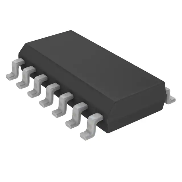
- Part No.:
- MICRF001BM
- Manufacturer:
- Microchip Technology
- Category:
- RF Receivers
- Package:
- 14-SOIC (0.154", 3.90mm Width)
- Datasheet:
-
 MICRF001BM.pdf
- Description:
- RF RCVR OOK 300MHZ-440MHZ 14SOIC
- Quantity:
- Payment:

- Shipping:

Inventory:1,370
Please send an inquiry. Send us your inquiry, and we will respond immediately.
Product details
Overview
MICRF001BM from Micrel Inc. is a monolithic UHF OOK (ON-OFF Keyed) receiver IC designed for antenna-in/data-out wireless remote control systems operating at 300–440 MHz, with typical decode range >100 m using a monopole antenna, data rates up to 4.8 kbps, and integrated automatic tuning eliminating manual RF alignment. It serves as the complete front-end demodulator in keyless entry, security, and garage door opener receivers.
For engineers reviewing the MICRF001BM datasheet, MICRF001BM pinout, MICRF001BM application, or MICRF001BM equivalent, this page delivers verified functional identity, confirmed 14-pin SOIC package mapping, validated four-bandwidth programmable LPF architecture, real-world sensitivity (-95 dBm), and two field-validated alternative receivers with documented interface and selectivity trade-offs.
Technical Context
The MICRF001BM implements a patented SWP (Swept Local Oscillator) architecture enabling ±0.5% transmitter frequency drift tolerance without retuning-critical for LC-based transmitters-while supporting fixed superheterodyne mode via SWEN pin grounding for SAW/crystal-stable systems. Its on-chip AGC uses CAGC capacitor to set attack/decay ratio (10:1 fixed), and internal switched-cap "resistor" RSC dynamically scales with filter bandwidth selection.
All RF/IF tuning is performed autonomously using a single external ceramic resonator (e.g., 3.00 MHz) connected to REFOSC, with ±0.5% initial tolerance sufficiency. Demodulation includes fully integrated post-detection filtering across four selectable low-pass bandwidths (0.6–4.8 kHz), each paired with a defined CTH source impedance (200k–1600kΩ) for precise slicing level time-constant design.
Key Specifications
| Parameter | Value and Actual Design Meaning |
|---|---|
| Frequency Range | 300–440 MHz RF input band; supports both SAW and LC transmitters without manual alignment. |
| Receiver Sensitivity | -95 dBm at 2400 bps, 10⁻² BER; defines minimum detectable signal under matched 50Ω conditions. |
| Data Rate Support | 0.1–4.8 kbps; compatible with Manchester and 33/66% PWM coding schemes. |
| Supply Voltage | 4.75–5.5 V; dual-rail VDDRF/VDDBB with separate RF/baseband ground returns (VSSRF/VSSBB). |
| Operating Current | 6.3 mA typical at 25°C; drops to 2 mA when reference oscillator is powered down. |
| Filter Bandwidths | Four user-selectable LPF options: 0.6/1.2/2.4/4.8 kHz via SEL0/SEL1 pins; sets CTH time constant and noise rejection profile. |
| Output Interface | CMOS-compatible DO pin; 0.9VDD high / 0.1VDD low at 1 µA load; drives standard decoders (e.g., HT-12D) directly. |
Pinout & Package
MICRF001BM is housed in a 14-pin SOIC package (JEDEC MS-012AC), pin-compatible with the DIP variant MICRF001BN but with reduced footprint and thermal resistance (θJA ≈ 140°C/W vs. 90°C/W for DIP).
| Pin/Terminal | Circuit Role | Design Meaning |
|---|---|---|
| 1 (SEL0) | Bandwidth control input | Binary LSB for selecting one of four LPF bandwidths; internally pulled up to VDD; requires no external pull-up. |
| 2/3 (VSSRF) | RF section ground return | Dedicated low-noise ground path for RF circuitry; must be isolated from VSSBB except at power supply node to prevent coupling. |
| 4 (ANT) | RF input terminal | High-impedance FET-gate input (≈2 pF shunt); accepts direct antenna connection; optional band-pass network possible for EMI immunity. |
| 5 (VDDRF) | RF supply rail | Positive supply for RF/IF stages; must be tied directly to VDDBB at IC pins; bypassed to VSSRF with low-ESL capacitor. |
| 6 (VDDBB) | Baseband supply rail | Positive supply for demodulator and digital logic; tied directly to VDDRF at IC pins; bypassed to VSSBB. |
| 7 (CTH) | DC slicing reference node | Extracts average demodulated waveform level; external capacitor value depends on selected bandwidth and desired time constant (5–50 ms). |
| 8 (DO) | Data output | CMOS-level push-pull output; directly interfaces microcontrollers or decoder ICs (e.g., HT-12D); 10 µA drive capability. |
| 9/10 (VSSBB) | Baseband ground return | Dedicated ground for baseband circuits; kept separate from VSSRF except at common supply point to avoid noise injection. |
| 11 (CAGC) | AGC timing capacitor node | External capacitor sets AGC attack time constant; decay/attack ratio fixed at 10:1; enables wide dynamic range (−20 to −95 dBm). |
| 12 (SEL1) | Bandwidth control input | Binary MSB for LPF selection; used with SEL0 to configure 0.6/1.2/2.4/4.8 kHz filters. |
| 13 (REFOSC) | Reference oscillator input | Accepts ceramic resonator (no integral caps), crystal, or AC-coupled 0.5 VPP external clock; Colpitts-type internal oscillator. |
| 14 (SWEN) | Mode selection control | High = SWP mode (swept LO, tolerant of ±0.5% TX drift); Low = fixed superheterodyne mode; internally pulled up to VDD. |
Key Features
| Feature | Design Value |
|---|---|
| Single-chip UHF OOK receiver | Eliminates all external filters, inductors, and manual tuning components-only CTH, CAGC, REFOSC resonator, and decoupling caps required. |
| Programmable demodulator LPF | Four bandwidth options (0.6–4.8 kHz) selected via two logic pins, enabling optimization for data rate, noise immunity, and range. |
| SWP architecture | Enables interoperability with low-cost LC transmitters by sweeping LO over ±2–3% band, removing need for tight TX frequency stability. |
| Integrated AGC with fixed 10:1 decay/attack ratio | Extends usable input dynamic range from −20 dBm to −95 dBm using only one external capacitor (CAGC). |
| Direct CMOS logic interface | DO pin outputs rail-to-rail CMOS levels compatible with standard decoders (HT-12D) and microcontroller GPIOs without level-shifting. |
Applications
| Keyless Entry Systems | Security Alarm Panels |
|---|---|
|
Use Scenario: Vehicle door unlock command transmitted via 315 MHz OOK signal from handheld fob. IC Role / Device Role / Timing Role: MICRF001BM acts as the sole RF front-end and OOK demodulator, converting antenna signal to clean CMOS data stream for address decoding. Use Value: Enables <100 µA standby current (with oscillator off) and >100 m range using compact PCB trace antenna-reducing BOM count by 7+ discrete RF components. |
Use Scenario: Wireless motion sensor reporting intrusion events to central panel via 433.92 MHz link. IC Role / Device Role / Timing Role: MICRF001BM provides selective reception in noisy residential environments, rejecting adjacent FM broadcast and pager interference via programmable 1.2 kHz LPF. Use Value: Achieves reliable 50 m indoor range with 2.4 kHz filter setting while maintaining compatibility with low-cost LC transmitters-cutting system cost vs. crystal-based alternatives. |
| Garage Door Openers | Remote Fan/Light Controllers |
|
Use Scenario: Push-button transmitter activates garage motor using 387 MHz OOK signal in residential setting. IC Role / Device Role / Timing Role: MICRF001BM operates in SWP mode (SWEN = HIGH) to accommodate ±0.5% frequency drift from aging LC tank, ensuring long-term reliability without recalibration. Use Value: Eliminates need for factory tuning stations and reduces production test time by >90%, accelerating time-to-market for OEM remotes. |
Use Scenario: Wall-mounted RF switch controlling ceiling fan speed and light dimming via 315 MHz OOK packets. IC Role / Device Role / Timing Role: MICRF001BM's 0.6 kHz LPF and CTH time constant optimized for 1.2 kbps Manchester-encoded commands suppress ambient noise in electrically noisy home environments. Use Value: Delivers error-free operation at 30 m through drywall and wood framing-achieving same robustness as higher-cost superheterodyne receivers at ~40% lower BOM cost. |
Equivalent & Alternatives
The following parts are listed as comparable options for similar OOK receiver applications.
| Alternative Part | Technical Difference | Application Difference | Selection Advice |
|---|---|---|---|
| Silicon Labs Si4322-B1B-FM | Higher sensitivity (−114 dBm), narrower IF bandwidth (120 kHz), requires external LNA and matching network; 24-pin QFN. | Better suited for ultra-low-power battery-operated sensors requiring sub-µA sleep current and longer range. | Select Si4322-B1B-FM only if system demands >150 m range or integration into multi-protocol SoC designs; adds layout complexity and cost. |
| ON Semiconductor NB3N502DG | Fixed 433.92 MHz OOK receiver; no bandwidth programming or SWP mode; simpler 8-pin SOIC; −102 dBm sensitivity. | Ideal for cost-sensitive, single-frequency applications where transmitter stability is guaranteed (e.g., SAW-based remotes). | Choose NB3N502DG when frequency is fixed and design prioritizes minimal external parts over flexibility-MICRF001BM remains superior for multi-band or LC-transmitter use. |
Compared with Si4322-B1B-FM and NB3N502DG, the MICRF001BM uniquely balances low BOM count, programmable selectivity, and SWP-mode drift tolerance-making it optimal for high-volume, multi-frequency remote control systems where transmitter cost and production scalability are critical.
Availability
MICRF001BM is available at Aetrix Electronics and suitable for keyless entry systems, security alarm panels, garage door openers, and remote fan/light controllers requiring stable component supply across automotive, industrial, and consumer electronics programs.
Supply support for MICRF001BM includes scheduled delivery planning, volume procurement assistance, BOM continuity management, traceable sourcing, and lifecycle availability coordination for OEM customers, industrial embedded developers, connected-device designers, and electronics production programs.
Manufacturer
Micrel Inc. was a U.S.-based analog and mixed-signal semiconductor company headquartered in San Jose, CA, specializing in power management, RF, and timing solutions before its acquisition by Microchip Technology in 2015.
The MICRF001BM belongs to Micrel's QwikRadio™ family of single-chip UHF receivers, engineered specifically for low-cost, high-volume wireless remote control applications demanding minimal external components and production-line tunability.
FAQ
What is the primary function of the MICRF001BM in a wireless system?
The MICRF001BM serves as a complete monolithic OOK receiver IC that converts RF signals from 300–440 MHz antennas directly into CMOS-level digital data. It integrates RF amplification, mixing, IF filtering, AGC, and demodulation-eliminating the need for external filters, inductors, or manual tuning. In a typical system, the MICRF001BM feeds decoded data to a logic decoder like the HT-12D or microcontroller GPIO, making it the core RF front-end for remote control receivers.
How does the SWP mode of the MICRF001BM improve compatibility with LC-based transmitters?
The SWP (Swept Local Oscillator) mode allows the MICRF001BM to automatically adjust its LO frequency across a ±2–3% band around the nominal transmit frequency, accommodating up to ±0.5% drift from LC transmitter aging, temperature, and tolerance. This eliminates the need for precise crystal or SAW references on the transmitter side. When SWEN = HIGH, the MICRF001BM enters SWP mode-enabling robust interoperability with low-cost LC transmitters while maintaining >100 m range and low bit error rate.
Which external components are mandatory for basic operation of the MICRF001BM?
Four external components are mandatory: (1) CAGC capacitor (typically 0.047 µF X7R) for AGC timing, (2) CTH capacitor (value depends on selected LPF bandwidth and desired slicing time constant), (3) REFOSC timing element (ceramic resonator, e.g., 3.00 MHz CSA3.00MG, without integral capacitors), and (4) decoupling capacitors-low-ESL 0.1 µF from VDDRF to VSSRF and from VDDBB to VSSBB. No inductors, transformers, or external filters are required.
Can the MICRF001BM operate with a crystal instead of a ceramic resonator?
Yes-the MICRF001BM's REFOSC pin supports three timing configurations: ceramic resonator (standard), quartz crystal, or externally supplied AC-coupled 0.5 VPP clock. When using a crystal, the device operates in fixed superheterodyne mode (SWEN = LOW), improving selectivity against close-in interferers but requiring tighter transmitter frequency stability. Crystal use is recommended only for SAW- or crystal-based transmitter systems where maximum adjacent-channel rejection is needed.
What is the significance of separating VSSRF and VSSBB ground pins on the MICRF001BM?
VSSRF and VSSBB are physically separate ground terminals to isolate high-frequency RF return currents from sensitive baseband logic and demodulator circuits. Routing RF noise through the baseband ground path would degrade sensitivity and increase bit error rate. The MICRF001BM datasheet specifies connecting VSSRF and VSSBB only at the main power supply node-ensuring clean signal integrity. Failure to observe this separation can reduce effective range by >30% and cause intermittent decoding failures.
MICRF001BM Specifications
- Product attributes
- Attribute value
- Manufacturer:
- Microchip Technology
- Series:
- -
- Package/Case:
- 14-SOIC (0.154", 3.90mm Width)
- Packaging:
- Bulk
- Product Status:
- Discontinued at Digi-Key
- Frequency:
- 300MHz ~ 440MHz
- Sensitivity:
- -95dBm
- Data Rate (Max):
- 4.8kbps
- Modulation or Protocol:
- OOK
- Applications:
- Garage Door, RKE
- Current - Receiving:
- 6.3mA
- Data Interface:
- PCB, Surface Mount
- Memory Size:
- -
- Antenna Connector:
- PCB, Surface Mount
- Features:
- Automatic Tuning
- Voltage - Supply:
- 4.75V ~ 5.5V
- Operating Temperature:
- -40°C ~ 85°C
- Grade:
- -
- Qualification:
- -
- Mounting Type:
- Surface Mount
- Supplier Device Package:
- 14-SOIC
MICRF001BM FAQ
1.How can I place an order for MICRF001BM through Aetrix?
Please submit a Request for Quotation (RFQ) for MICRF001BM on Aetrix. Our sales agent will provide a competitive quotation and guide you through the order confirmation once you accept the terms.
2.Are the price and stock information for MICRF001BM reliable?
The price and inventory of MICRF001BM are updated periodically and may fluctuate due to market conditions. Stock and pricing data are typically refreshed every 24 hours. Quotation validity for MICRF001BM is usually 5 days.
3.What payment methods are accepted for MICRF001BM?
We accept Wire Transfer, PayPal, Credit Card, Western Union, MoneyGram, and Escrow for MICRF001BM transactions.
Note: Certain payment methods may incur a processing fee.
4.How is shipping managed for MICRF001BM?
MICRF001BM orders can be shipped via leading logistics carriers, including DHL, UPS, FedEx, TNT, or Registered Mail.
Once your MICRF001BM order is processed, you will receive an email with the shipment details and tracking number.
Note: Tracking information may take up to 24 hours to appear. Express delivery typically takes 3–5 business days.
5.How can I obtain technical support or documentation for MICRF001BM?
For technical support, including MICRF001BM datasheets, pinout diagrams, or application guidance, please contact our engineering support team. They can provide detailed documentation and assistance for your MICRF001BM requirements.
6.How does Aetrix verify that MICRF001BM is sourced from the original manufacturer or authorized distributors?
All MICRF001BM products on Aetrix are procured from qualified distributors and authorized channels. Our dedicated quality assurance team conducts strict verification, including traceability checks and, if necessary, third-party testing. This ensures that MICRF001BM meets industry standards.
7.What is the process for return or replacement of MICRF001BM?
All MICRF001BM units undergo pre-shipment inspection (PSI). If there is an issue with MICRF001BM, returns or replacements are accepted under the following conditions:
1.Quantity discrepancies, incorrect items, or visible external defects (such as breakage or corrosion), acknowledged by Aetrix.
2.The issue is reported within 90 days of delivery.
3.The MICRF001BM part is unused and in its original packaging.
Return procedure for MICRF001BM:
1.Submit a request within 90 days.
2.Obtain a Return Material Authorization (RMA) from Aetrix.
MICRF001BM Tags
-
MICRF220AYQS-TR
Microchip Technology
-
SX1239IMLTRT
Semtech Corporation

-
SI4356-B1A-FMR
Silicon Labs

-
SI4362-C2A-GMR
Silicon Labs

-
MAX1473EUI+T
Analog Devices Inc./Maxim Integrated

-
CMX992Q3
CML Micro

-
CMX994AQ4
CML Micro

-
MAX2112ETI+
Analog Devices Inc./Maxim Integrated
-
MAX2112ETI+T
Analog Devices Inc./Maxim Integrated
-
TESEO-LIV3R
STMicroelectronics
-
M20048-1
Antenova
-
CMX994EQ4
CML Micro
Tech Hub

TTL and CMOS logic families differ in thresholds, loading, output drive, power and timing. This engineering guide compares 74HC and 74HCT, calculates noise margins and checks 3.3 V/5 V compatibility.

A practical engineering guide to 3.3V and 5V logic compatibility, input thresholds, resistor dividers, translator ICs, MOSFET level shifting, I2C pull-ups, timing limits and power-sequencing risks.

The 74HC595 uses push-pull logic outputs, while the TPIC6B595 uses 50 V open-drain DMOS sinks for higher-power loads. This guide compares timing, current limits, 3.3 V interfacing, load wiring, thermal…

The 74HC595 converts serial data into eight stable parallel outputs. This guide covers pin functions, shift and storage timing, OE and MR behavior, drive-current limits, cascading, voltage compatibilit…

A technical comparison of level-sensitive latches and edge-triggered flip-flops, covering timing windows, setup and hold limits, master–slave operation, time borrowing, race-through, HDL inference and…

A D latch stores one bit while Enable controls when data can pass. This reference covers gate-level operation, truth tables, transparency, setup and hold timing, LE versus OE, common ICs and practical …

An SR latch stores one bit through cross-coupled feedback. This engineering reference covers NOR and NAND implementations, truth tables, forbidden-state recovery, gated operation, switch debouncing, fa…

Latch circuits retain one bit through feedback. This technical reference covers SR and D latches, truth tables, transparency, timing limits, latch-versus-flip-flop behavior, applications and common log…

An engineering guide to LED driver operation, constant-current and constant-voltage outputs, linear and switching topologies, dimming, IC selection, calculations, replacement compatibility, and fault c…

Operational amplifier guide covering op amp basics, feedback, ideal vs real op amps, common configurations, buffer circuits, offset, bias current, gain-bandwidth, slew rate, rail-to-rail limits and sel…


