
 My Inquiry
 My Account


Renesas MK712R
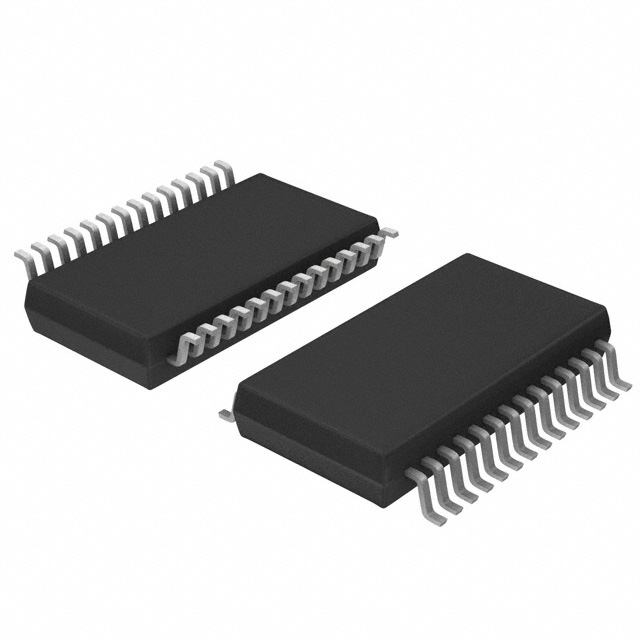
- Part No.:
- MK712R
- Manufacturer:
- Renesas
- Category:
- Touch Screen Controllers
- Package:
- 28-SSOP (0.154", 3.90mm Width)
- Datasheet:
-
 MK712R.pdf
- Description:
- IC SCREEN CNTRL 12BIT 28QSOP
- Quantity:
- Payment:

- Shipping:

Inventory:4,397
Please send an inquiry. Send us your inquiry, and we will respond immediately.
Product details
Overview
MK712R from Integrated Device Technology (IDT) is a 4-wire analog resistive touch screen controller IC with integrated 12-bit ratiometric A/D converter, parallel interface, and ultra-low standby current of 0.5 µA (typical at 5.0 V). It continuously monitors touch activity, performs up to 197 points/second conversions, stores X/Y coordinates in internal registers, and asserts an interrupt signal-enabling direct integration into industrial HMI panels and automotive infotainment displays.
For engineers reviewing the MK712R datasheet, MK712R pinout, MK712R application, or MK712R equivalent, key selection considerations include its 28-pin SSOP package, 3.3 V/5 V dual-supply support, monotonic 12-bit ADC, programmable conversion rate, and compatibility with Gazelle pen digitizer register mapping for software reuse.
Technical Context
The MK712R implements a dedicated analog front-end for 4-wire resistive touch screens, applying voltage across X-plate (XH/XL) or Y-plate (YH/YL) and measuring the resulting ratiometric voltage on the orthogonal plate. Its internal timing engine synchronizes sampling with clock input (12–20 MHz), supports automatic wake-up from sub-3 µA power-down mode upon touch detection, and uses register-based control (8×8-bit registers) for configuration and data retrieval.
Operation relies on parallel bus interface (8-bit bidirectional data bus D0–D7, address lines A0–A2, RD/WR/CS controls) and discrete touch-screen drive pins (XH, XL, YH, YL, TOUCH). The IC requires no external transistors-capacitors are the only external components-and features built-in debouncing logic tied to screen decoupling time constants.
Key Specifications
| Parameter | Value and Actual Design Meaning |
|---|---|
| Supply Voltage | 3.0–5.5 V (commercial/industrial); 3.135–5.5 V (automotive) - supports dual-rail system integration without level shifters. |
| Standby Current | 0.5 µA typical at 5 V - enables battery-backed operation in portable HMIs with multi-week sleep duration. |
| Max Conversion Rate | 197 points/second - ensures responsive user interaction on 10.5" displays with ≥350 dpi resolution capability. |
| A/D Resolution | 12-bit monotonic ratiometric - eliminates need for per-unit calibration by referencing full-scale to applied screen voltage. |
| Operating Temperature | -35°C to +85°C - qualified for under-dash automotive environments per ordering suffix RWLFTR. |
| Input Clock Range | 12–20 MHz - tolerates wide frequency variation; 14.318 MHz recommended for optimal noise immunity and power efficiency. |
| Touch Screen Resistance | 100–2000 Ω - compatible with standard off-the-shelf 4-wire resistive overlays without external buffering. |
Pinout & Package
Packaged in 28-pin SSOP (150 mil wide body), JEDEC MS-012AC compliant, with 0.635 mm pitch and 9.80–10.00 mm body length. Pin 1 is NC (no connect); all VDD pins must be tied to same supply rail; GND pins (10, 11, 13, 21) require low-inductance grounding.
| Pin/Terminal | Circuit Role | Design Meaning |
|---|---|---|
| INT (2) | Interrupt output | Active-high signal indicating valid X/Y coordinate capture; cleared by any register read - enables interrupt-driven firmware polling. |
| TOUCH (3) | Touch status output | Drives low when screen contact is detected - provides hardware-level touch presence flag independent of conversion cycle. |
| XH (6), XL (7), YH (8), YL (9) | Touch screen interface | Direct connection to resistive overlay electrodes - eliminates external driver transistors and reduces BOM count. |
| RD (13), WR (12), CS (14), A0–A2 (15–17) | Parallel bus control | Standard 8080-style memory-mapped interface - simplifies integration with microcontrollers lacking SPI/I²C peripherals. |
| D0–D7 (19, 20, 23–28) | Data I/O | Bidirectional 8-bit data path for register reads/writes - supports byte-aligned access to 8×8-bit register set including rate and power-down controls. |
| CLKIN (18) | Clock input | Accepts 12–20 MHz CMOS clock - internal timing engine derives sampling intervals and conversion sequencing from this source. |
Key Features
| Feature | Design Value |
|---|---|
| Ratiometric 12-bit A/D conversion | Eliminates dependency on absolute VDD stability and screen resistance drift - delivers consistent coordinate accuracy across temperature and aging. |
| 0.5 µA standby current | Enables always-on touch readiness in energy-constrained applications such as automotive keyless entry interfaces or medical handhelds. |
| Register compatibility with Gazelle digitizer | Allows reuse of existing driver software stack - reduces firmware development time and validation effort for legacy system upgrades. |
| Capacitor-only external components | Removes need for external op-amps, transistors, or precision references - cuts PCB area and improves long-term reliability. |
| Programmable conversion rate (up to 197 PPS) | Permits dynamic trade-off between responsiveness and power consumption - adjustable via Rate Register (Register 7) for application-specific optimization. |
Applications
| Automotive Infotainment Display | Industrial HMI Panel |
|---|---|
Use Scenario: Touch-enabled navigation and climate control interface mounted in vehicle cabin with wide ambient temperature swings. IC Role / Device Role / Timing Role: Primary touch coordinate acquisition engine interfacing directly to 4-wire resistive overlay; manages autonomous wake-up and low-power monitoring. Use Value: -35°C to +85°C operating range (MK712RWLFTR variant) ensures reliable operation under dash-mounted thermal stress without active cooling. | Use Scenario: Factory-floor operator terminal exposed to dust, vibration, and ESD events in manufacturing automation systems. IC Role / Device Role / Timing Role: Standalone touch controller handling coordinate digitization and interrupt generation for ARM Cortex-M host MCU. Use Value: 0.5 µA standby current extends battery backup runtime during mains power loss; robust 2000 Ω screen resistance tolerance accommodates aged overlays. |
| Medical Handheld Device | Retail Point-of-Sale Terminal |
Use Scenario: Disinfectant-resistant tablet used for patient data entry in clinical environments requiring glove-compatible touch response. IC Role / Device Role / Timing Role: Low-noise analog front-end converting physical pressure into digital X/Y positions; ratiometric ADC rejects supply ripple from shared medical-grade DC-DC converters. Use Value: Monotonic 12-bit conversion guarantees no missing codes during rapid swipes - critical for accurate signature capture and gesture recognition. | Use Scenario: Compact countertop POS system with integrated resistive touchscreen for cashier interaction in high-traffic retail settings. IC Role / Device Role / Timing Role: Dedicated controller managing touch polling, coordinate storage, and interrupt signaling to application processor over parallel bus. Use Value: Parallel interface avoids software overhead of bit-banged SPI/I²C - delivers deterministic <1 ms latency from touch to host interrupt assertion. |
Equivalent & Alternatives
The following parts are listed as comparable options for similar touch screen controller applications.
| Alternative Part | Technical Difference | Application Difference | Selection Advice |
|---|---|---|---|
| AK4183VT-EVAL | 8-bit resolution, I²C interface, no built-in touch detection logic - requires external MCU polling. | Limited to low-resolution overlays (<200 dpi); unsuitable for automotive temperature range. | Consider only for cost-sensitive consumer electronics where resolution and temperature range are secondary. |
| TSC2007IPW | 12-bit delta-sigma ADC, I²C/SPI interface, integrated charge pump for VREF - higher active current (600 µA typical). | Supports both 4-wire and 5-wire touch; lacks native Gazelle register compatibility. | Prefer when multi-touch or higher noise immunity is required, but expect firmware rework and increased power budget. |
Compared with AK4183VT-EVAL and TSC2007IPW, the MK712R delivers superior integration (parallel interface, touch detection, ultra-low standby), guaranteed monotonicity, and automotive qualification - making it optimal for deterministic, low-power, single-touch HMI designs where software reuse and thermal robustness are priorities.
Availability
MK712R is available at Aetrix Electronics and suitable for automotive infotainment displays, industrial HMI panels, and medical handheld devices requiring stable component supply across extended temperature ranges and long production lifecycles.
Supply support for MK712R includes scheduled delivery planning, volume procurement assistance, BOM continuity management, traceable sourcing, and lifecycle availability coordination for OEM customers, industrial embedded developers, connected-device designers, and electronics production programs.
Manufacturer
Integrated Device Technology (IDT) is a fabless semiconductor company specializing in timing, memory interface, RF, and sensor signal conditioning solutions for communications, computing, and industrial markets.
The MK712R belongs to IDT's touch screen controller product line, designed specifically to simplify integration of 4-wire resistive touchscreens into resource-constrained embedded systems through fully integrated analog front-end, low-power operation, and register-level software compatibility.
FAQ
What is the primary function of the MK712R in a touch-enabled system?
The MK712R serves as a dedicated 4-wire analog resistive touch screen controller IC that performs real-time X/Y coordinate digitization using a 12-bit ratiometric A/D converter, manages autonomous touch detection and wake-up, stores results in internal registers, and signals completion via the INT pin. It eliminates the need for external analog circuitry or MCU-based polling loops, enabling deterministic, low-latency touch response in systems like automotive displays and industrial HMIs.
Does the MK712R support both 3.3 V and 5 V supply rails?
Yes, the MK712R operates across a supply voltage range of 3.0–5.5 V for commercial and industrial grades, and 3.135–5.5 V for automotive-grade variants (e.g., MK712RWLFTR). All VDD pins (4, 5, 22) must be connected to the same rail, and the device maintains full functionality-including 0.5 µA standby current and 197 PPS conversion rate-across both voltages without configuration changes.
How does the MK712R achieve calibration-free operation?
The MK712R uses a ratiometric A/D conversion technique where the full-scale reference is derived directly from the voltage applied across the touch screen plates. This makes coordinate values independent of absolute VDD variations, screen resistance drift, and temperature shifts. As a result, the MK712R can deliver repeatable X/Y positions without factory or runtime calibration-though parasitic interconnect resistance may reduce usable full-scale range by ~20%.
What package type is used for the MK712R, and is it RoHS-compliant?
The MK712R is packaged in a 28-pin SSOP (150 mil wide body) with 0.635 mm lead pitch, compliant with JEDEC MS-012AC. Ordering suffixes "LF" or "WLF" (e.g., MK712RWLFTR) indicate lead-free, RoHS-compliant construction. The SSOP footprint offers higher density than SOIC while maintaining hand-solderability and compatibility with standard SMT assembly processes.
Can existing Gazelle digitizer software drivers be reused with the MK712R?
Yes-the MK712R register map is explicitly designed to match the Gazelle pen digitizer, supporting identical 8×8-bit register addressing (Registers 0–7) and command sequences. This allows direct reuse of mature Gazelle driver stacks in embedded Linux, RTOS, or bare-metal firmware without modification, significantly reducing integration time and validation risk for legacy system upgrades.
MK712R Specifications
- Product attributes
- Attribute value
- Manufacturer:
- Renesas
- Package/Case:
- 28-SSOP (0.154", 3.90mm Width)
- Touchscreen:
- 4 Wire Resistive
- Resolution (Bits):
- 12 b
- Interface:
- Parallel
- Voltage Reference:
- -
- Voltage - Supply:
- 3V ~ 5.5V
- Current - Supply:
- 5 mA
- Operating Temperature:
- -
- Mounting Type:
- Surface Mount
- Grade:
- -
- Qualification:
- -
- Supplier Device Package:
- 28-QSOP
MK712R FAQ
1.How can I place an order for MK712R through Aetrix?
Please submit a Request for Quotation (RFQ) for MK712R on Aetrix. Our sales agent will provide a competitive quotation and guide you through the order confirmation once you accept the terms.
2.Are the price and stock information for MK712R reliable?
The price and inventory of MK712R are updated periodically and may fluctuate due to market conditions. Stock and pricing data are typically refreshed every 24 hours. Quotation validity for MK712R is usually 5 days.
3.What payment methods are accepted for MK712R?
We accept Wire Transfer, PayPal, Credit Card, Western Union, MoneyGram, and Escrow for MK712R transactions.
Note: Certain payment methods may incur a processing fee.
4.How is shipping managed for MK712R?
MK712R orders can be shipped via leading logistics carriers, including DHL, UPS, FedEx, TNT, or Registered Mail.
Once your MK712R order is processed, you will receive an email with the shipment details and tracking number.
Note: Tracking information may take up to 24 hours to appear. Express delivery typically takes 3–5 business days.
5.How can I obtain technical support or documentation for MK712R?
For technical support, including MK712R datasheets, pinout diagrams, or application guidance, please contact our engineering support team. They can provide detailed documentation and assistance for your MK712R requirements.
6.How does Aetrix verify that MK712R is sourced from the original manufacturer or authorized distributors?
All MK712R products on Aetrix are procured from qualified distributors and authorized channels. Our dedicated quality assurance team conducts strict verification, including traceability checks and, if necessary, third-party testing. This ensures that MK712R meets industry standards.
7.What is the process for return or replacement of MK712R?
All MK712R units undergo pre-shipment inspection (PSI). If there is an issue with MK712R, returns or replacements are accepted under the following conditions:
1.Quantity discrepancies, incorrect items, or visible external defects (such as breakage or corrosion), acknowledged by Aetrix.
2.The issue is reported within 90 days of delivery.
3.The MK712R part is unused and in its original packaging.
Return procedure for MK712R:
1.Submit a request within 90 days.
2.Obtain a Return Material Authorization (RMA) from Aetrix.
MK712R Tags

-
TSC2046IPWR
Texas Instruments
-
TSC2007IPWR
Texas Instruments
-
TSC2046EIPWR
Texas Instruments
-
AR1021-I/SS
Microchip Technology
-
AR1020-I/SS
Microchip Technology
-
AR1100-I/MQ
Microchip Technology
-
AR1021T-I/ML
Microchip Technology
-
AR1100T-I/SS
Microchip Technology
-
TSC2003IPWR
Texas Instruments
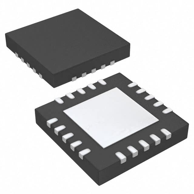
-
TSC2004IRTJR
Texas Instruments
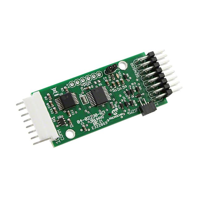
-
AR1100BRD
Microchip Technology
.jpg)
-
TSC2046IRGVR
Texas Instruments
Tech Hub

TTL and CMOS logic families differ in thresholds, loading, output drive, power and timing. This engineering guide compares 74HC and 74HCT, calculates noise margins and checks 3.3 V/5 V compatibility.

A practical engineering guide to 3.3V and 5V logic compatibility, input thresholds, resistor dividers, translator ICs, MOSFET level shifting, I2C pull-ups, timing limits and power-sequencing risks.

The 74HC595 uses push-pull logic outputs, while the TPIC6B595 uses 50 V open-drain DMOS sinks for higher-power loads. This guide compares timing, current limits, 3.3 V interfacing, load wiring, thermal…

The 74HC595 converts serial data into eight stable parallel outputs. This guide covers pin functions, shift and storage timing, OE and MR behavior, drive-current limits, cascading, voltage compatibilit…

A technical comparison of level-sensitive latches and edge-triggered flip-flops, covering timing windows, setup and hold limits, master–slave operation, time borrowing, race-through, HDL inference and…

A D latch stores one bit while Enable controls when data can pass. This reference covers gate-level operation, truth tables, transparency, setup and hold timing, LE versus OE, common ICs and practical …

An SR latch stores one bit through cross-coupled feedback. This engineering reference covers NOR and NAND implementations, truth tables, forbidden-state recovery, gated operation, switch debouncing, fa…

Latch circuits retain one bit through feedback. This technical reference covers SR and D latches, truth tables, transparency, timing limits, latch-versus-flip-flop behavior, applications and common log…

An engineering guide to LED driver operation, constant-current and constant-voltage outputs, linear and switching topologies, dimming, IC selection, calculations, replacement compatibility, and fault c…

Operational amplifier guide covering op amp basics, feedback, ideal vs real op amps, common configurations, buffer circuits, offset, bias current, gain-bandwidth, slew rate, rail-to-rail limits and sel…


