
 My Inquiry
 My Account


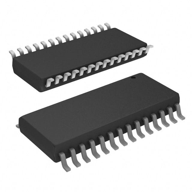
Renesas MK712SLFTR
- Part No.:
- MK712SLFTR
- Manufacturer:
- Renesas
- Category:
- Touch Screen Controllers
- Package:
- 28-SOIC (0.295", 7.50mm Width)
- Datasheet:
-
 MK712SLFTR.pdf
- Description:
- IC SCREEN CNTRL 12BIT 28SOIC
- Quantity:
- Payment:

- Shipping:

Inventory:2,192
Please send an inquiry. Send us your inquiry, and we will respond immediately.
Product details
Overview
MK712SLFTR from Integrated Device Technology (IDT) is a 4-wire analog resistive touch screen controller IC with integrated 12-bit ratiometric A/D converter, parallel interface, and ultra-low standby current of 0.5 µA (typical at 5.0 V). It continuously monitors touch events, performs X/Y coordinate conversion at up to 197 points/second, stores results in internal registers, and asserts an interrupt signal-enabling direct integration into industrial HMI panels and embedded display systems.
For engineers reviewing the MK712SLFTR datasheet, MK712SLFTR pinout, MK712SLFTR application, or MK712SLFTR equivalent, this page delivers verified technical context-including confirmed 28-pin SOIC package mapping, parallel register interface timing, automotive-grade temperature support (-35°C to +85°C variant available), and real-world design implications of its ratiometric ADC architecture for calibration-free operation.
Technical Context
The MK712SLFTR implements a dedicated analog front-end for 4-wire resistive touch screens, applying voltage across X or Y plates and measuring resulting voltages via a monotonic 12-bit ratiometric ADC. Its conversion rate is programmable via registers 6 and 7, supporting 86–197 points/second depending on configuration.
It uses a parallel 8-bit data bus (D0–D7) with discrete address lines (A0–A2), chip select (CS), read/write strobes (RD/WR), and clock input (CLKIN, 12–20 MHz). The TOUCH output pin signals screen contact state, while INT asserts on valid coordinate capture-cleared only by register read or power-down register write.
Key Specifications
| Parameter | Value and Actual Design Meaning |
|---|---|
| Supply Voltage | 3.0–5.5 V (commercial/industrial); enables direct use with 3.3 V or 5 V system rails without level-shifting. |
| Standby Current | 0.5 µA typical at 5 V - allows battery-backed HMIs to maintain touch readiness for weeks without significant drain. |
| Active Current | <10 mA during conversion - limits thermal load and simplifies power budgeting in compact displays. |
| ADC Resolution | 12-bit ratiometric - eliminates need for factory calibration by referencing full-scale to applied screen voltage, not fixed reference. |
| Max Conversion Rate | 197 points/second - supports responsive user interaction on 10.5" displays resolving 350 dots/inch. |
| Touch Interface | Direct 4-wire resistive drive - no external transistors or drivers required; XL/XH/YL/YH pins connect directly to screen electrodes. |
| Operating Temperature | 0°C to +70°C (MK712SLFTR) - validated for commercial panel applications; industrial (-30°C to +70°C) and automotive (-35°C to +85°C) variants exist. |
Pinout & Package
Packaged in 28-pin SOIC (300 mil wide body), JEDEC MS-013AC compliant, with 1.27 mm pitch and 17.7–18.4 mm body length. RoHS-compliant Pb-free finish (LF suffix).
| Pin/Terminal | Circuit Role | Design Meaning |
|---|---|---|
| 1 | NC | No-connect; must remain unconnected to avoid parasitic coupling or latch-up risk. |
| 2 | INT | Open-drain interrupt output; goes high on valid X/Y capture and clears only after register read or power-down register write. |
| 3 | TOUCH | Dedicated touch-status output; low during screen contact, high otherwise-enables hardware debouncing without CPU polling. |
| 4,5,22 | VDD | Power supply inputs; all must be tied to same 3.3 V or 5 V rail-decoupling required per datasheet layout guidelines. |
| 6,7,8,9 | XH, XL, YH, YL | Direct touch screen electrode connections; drive X/Y plates and sense resulting voltages-no external buffers needed. |
| 10,11,13,21 | GND | Four ground terminals; mandatory star grounding to minimize noise coupling into analog measurement path. |
| 12 | WR | Active-low write strobe; initiates register write when CS and address lines are stable-timing critical per TRCSW/TRWR specs. |
| 14 | CS | Chip select; must be asserted before RD/WR edges-supports shared bus operation with other peripherals. |
| 15–17 | A2–A0 | 3-bit register address bus; selects one of eight 8-bit registers (0–7) for read/write access-compatible with Gazelle digitizer software drivers. |
| 18 | CLKIN | 12–20 MHz clock input; 14.318 MHz recommended; undershoot/overshoot increases supply current-requires series termination per layout note. |
| 19–20,23–28 | D7–D0 | 8-bit bidirectional data bus; shares pins between read and write cycles-requires proper tristate control and bus loading management. |
Key Features
| Feature | Design Value |
|---|---|
| Ratiometric 12-bit ADC | Eliminates dependency on stable voltage reference-full-scale defined by applied screen voltage, enabling calibration-free startup in production. |
| Ultra-low standby current | 0.5 µA typical at 5 V allows continuous touch monitoring in battery-powered portable HMIs without compromising runtime. |
| Integrated touch drive circuitry | Direct connection to 4-wire resistive screen electrodes (XH/XL/YH/YL) removes need for external MOSFETs or op-amps-reducing BOM count and PCB area. |
| Programmable conversion rate | Configurable from 86 to 197 points/second via registers 6 and 7-balances responsiveness against power consumption and noise susceptibility. |
| Monotonic conversion guarantee | No missing codes over full 12-bit range ensures deterministic coordinate mapping-critical for accurate gesture recognition and UI navigation. |
Applications
| Industrial HMI Panels | Medical Display Terminals |
|---|---|
Use Scenario: Operator interface on factory-floor PLC panels with glove-compatible touch operation under variable ambient lighting and EMI conditions. IC Role / Device Role / Timing Role: Touch screen controller providing X/Y coordinate acquisition, interrupt-driven event signaling, and ratiometric ADC conversion independent of supply drift. Use Value: Enables reliable touch detection at 0.5 µA standby current and immunity to 3.0–5.5 V rail variation-reducing recalibration frequency and field service calls. |
Use Scenario: Patient monitor touchscreen requiring low-power, long-term reliability and immunity to clinical-grade ESD events. IC Role / Device Role / Timing Role: Primary touch acquisition IC interfacing to 4-wire resistive overlay, managing touch wake-up, coordinate capture, and register-based host communication. Use Value: Delivers monotonic 12-bit resolution and guaranteed no-missing-codes performance-ensuring precise cursor positioning for diagnostic UI navigation. |
| Automotive Infotainment Displays | Retail Kiosk Interfaces |
Use Scenario: In-vehicle center console display operating across -35°C to +85°C ambient with vibration and thermal cycling. IC Role / Device Role / Timing Role: Touch controller supporting extended temperature grade (via MK712RWLFTR variant), direct screen drive, and programmable PPS for adaptive responsiveness. Use Value: Validated automotive temperature range and ratiometric ADC eliminate cold-start calibration drift-improving first-touch accuracy after vehicle ignition. |
Use Scenario: Self-service retail kiosk exposed to high-use, variable environmental conditions and frequent firmware updates. IC Role / Device Role / Timing Role: Touch acquisition engine with parallel register interface, interrupt signaling, and software-compatible register map (Gazelle digitizer compatible). Use Value: Simplifies driver porting and reduces firmware development time-leveraging existing Gazelle-based touch stack without hardware modification. |
Equivalent & Alternatives
The following parts are listed as comparable options for similar touch screen controller applications.
| Alternative Part | Technical Difference | Application Difference | Selection Advice |
|---|---|---|---|
| TI TSC2007IPW | 12-bit SAR ADC, I²C interface, integrated touchscreen driver, 1.6–3.6 V supply; lacks parallel bus and programmable PPS register set. | Targets low-pin-count, low-power portable devices; requires I²C host support and external level shifters for 5 V systems. | Select when I²C bus availability and ultra-low active current (<600 µA) outweigh need for register compatibility and high-speed parallel throughput. |
| Microchip AR1021T-I/ML | 10-bit delta-sigma ADC, SPI interface, built-in gesture engine, 2.7–5.5 V supply; includes on-chip firmware for swipe/tap detection. | Designed for embedded gesture-aware interfaces; requires SPI host and lacks ratiometric full-scale independence from VDD. | Choose when advanced gesture processing is required and host MCU lacks resources for coordinate interpolation-accepting trade-off in absolute coordinate precision vs. MK712SLFTR. |
Compared with TI TSC2007IPW and Microchip AR1021T-I/ML, the MK712SLFTR provides deterministic parallel register access, ratiometric calibration-free operation, and higher maximum sampling rate (197 PPS), making it optimal for deterministic industrial HMIs where register-level control and minimal firmware overhead are prioritized.
Availability
MK712SLFTR is available at Aetrix Electronics and suitable for industrial HMI panels, medical display terminals, and retail kiosk interfaces requiring stable component supply, RoHS compliance, and long-term lifecycle continuity.
Supply support for MK712SLFTR includes scheduled delivery planning, volume procurement assistance, BOM continuity management, traceable sourcing, and lifecycle availability coordination for OEM customers, industrial embedded developers, connected-device designers, and electronics production programs.
Manufacturer
Integrated Device Technology (IDT), now part of Renesas Electronics, is a fabless semiconductor company specializing in timing, memory interface, RF, and sensor signal-path solutions for communications, computing, and industrial markets.
The MK712SLFTR belongs to IDT's legacy touch screen controller product line, designed specifically for cost-sensitive, high-reliability 4-wire resistive touch applications in commercial and industrial displays-prioritizing low power, minimal external components, and software compatibility with existing Gazelle-based drivers.
FAQ
What is the primary function of the MK712SLFTR in a touch-enabled system?
The MK712SLFTR serves as a dedicated 4-wire analog resistive touch screen controller IC. It drives the X and Y electrode plates, performs ratiometric 12-bit analog-to-digital conversion of touch coordinates, stores X/Y values in internal registers, and asserts an interrupt signal (INT) to notify the host processor. Its design eliminates the need for external transistors or calibration routines in many applications, and the MK712SLFTR operates with ultra-low standby current (0.5 µA typical) to extend battery life in portable HMIs.
Does the MK712SLFTR support both 3.3 V and 5 V supply rails?
Yes, the MK712SLFTR supports dual-supply operation: VDD may be either 3.3 V or 5 V, with specified operating ranges of 3.0–5.5 V (commercial/industrial) and 3.135–5.5 V (automotive). All VDD pins (pins 4, 5, and 22) must be connected to the same voltage rail, and appropriate decoupling capacitors are required per the datasheet layout recommendations. The MK712SLFTR's I/O thresholds scale accordingly-VIH is 1.9 V at 3.3 V supply and 2.0 V at 5 V supply-ensuring robust logic-level compatibility.
How does the ratiometric ADC in the MK712SLFTR improve system calibration requirements?
The MK712SLFTR's 12-bit ratiometric ADC defines full-scale (4095) based on the actual voltage applied across the touch screen electrodes-not a fixed internal reference. This makes coordinate measurements largely independent of variations in screen resistance, temperature, and supply voltage drift. As a result, the MK712SLFTR can often eliminate factory or runtime calibration steps, especially in stable mechanical assemblies. However, parasitic interconnect resistance accounts for ~20% of total screen resistance, rendering the outer ~10% of full-scale range inaccessible-a known design constraint of the MK712SLFTR's architecture.
What is the role of the TOUCH pin (pin 3) on the MK712SLFTR?
The TOUCH pin (pin 3) is a dedicated open-drain output that signals physical screen contact state: it goes low when the screen is touched and high when untouched. Unlike the INT pin-which asserts only after successful X/Y coordinate conversion-the TOUCH pin responds immediately to plate closure, enabling hardware-level debounce and fast wake-up decisions without CPU intervention. This behavior is intrinsic to the MK712SLFTR's analog sensing architecture and is unaffected by register configuration or conversion rate settings.
Can the MK712SLFTR be used with a switching regulator power supply?
The MK712SLFTR can be powered from a switching regulator, but screen conversions must not occur while the regulator is in burst-mode or other low-power noise-generating states. As documented in the datasheet, such modes introduce power supply noise that causes spurious coordinate readings. To ensure accuracy, the MK712SLFTR's conversion activity should be synchronized to periods when the regulator operates in continuous conduction mode-or the regulator's low-power mode must be disabled during touch acquisition. This requirement applies specifically to the MK712SLFTR's sensitive analog measurement path and is not mitigated by standard decoupling alone.
MK712SLFTR Specifications
- Product attributes
- Attribute value
- Manufacturer:
- Renesas
- Package/Case:
- 28-SOIC (0.295", 7.50mm Width)
- Touchscreen:
- 4 Wire Resistive
- Resolution (Bits):
- 12 b
- Interface:
- Parallel
- Voltage Reference:
- -
- Voltage - Supply:
- 3V ~ 5.5V
- Current - Supply:
- 5 mA
- Operating Temperature:
- 0°C ~ 70°C
- Mounting Type:
- Surface Mount
- Grade:
- -
- Qualification:
- -
- Supplier Device Package:
- 28-SOIC
MK712SLFTR FAQ
1.How can I place an order for MK712SLFTR through Aetrix?
Please submit a Request for Quotation (RFQ) for MK712SLFTR on Aetrix. Our sales agent will provide a competitive quotation and guide you through the order confirmation once you accept the terms.
2.Are the price and stock information for MK712SLFTR reliable?
The price and inventory of MK712SLFTR are updated periodically and may fluctuate due to market conditions. Stock and pricing data are typically refreshed every 24 hours. Quotation validity for MK712SLFTR is usually 5 days.
3.What payment methods are accepted for MK712SLFTR?
We accept Wire Transfer, PayPal, Credit Card, Western Union, MoneyGram, and Escrow for MK712SLFTR transactions.
Note: Certain payment methods may incur a processing fee.
4.How is shipping managed for MK712SLFTR?
MK712SLFTR orders can be shipped via leading logistics carriers, including DHL, UPS, FedEx, TNT, or Registered Mail.
Once your MK712SLFTR order is processed, you will receive an email with the shipment details and tracking number.
Note: Tracking information may take up to 24 hours to appear. Express delivery typically takes 3–5 business days.
5.How can I obtain technical support or documentation for MK712SLFTR?
For technical support, including MK712SLFTR datasheets, pinout diagrams, or application guidance, please contact our engineering support team. They can provide detailed documentation and assistance for your MK712SLFTR requirements.
6.How does Aetrix verify that MK712SLFTR is sourced from the original manufacturer or authorized distributors?
All MK712SLFTR products on Aetrix are procured from qualified distributors and authorized channels. Our dedicated quality assurance team conducts strict verification, including traceability checks and, if necessary, third-party testing. This ensures that MK712SLFTR meets industry standards.
7.What is the process for return or replacement of MK712SLFTR?
All MK712SLFTR units undergo pre-shipment inspection (PSI). If there is an issue with MK712SLFTR, returns or replacements are accepted under the following conditions:
1.Quantity discrepancies, incorrect items, or visible external defects (such as breakage or corrosion), acknowledged by Aetrix.
2.The issue is reported within 90 days of delivery.
3.The MK712SLFTR part is unused and in its original packaging.
Return procedure for MK712SLFTR:
1.Submit a request within 90 days.
2.Obtain a Return Material Authorization (RMA) from Aetrix.
MK712SLFTR Tags

-
TSC2046IPWR
Texas Instruments
-
TSC2007IPWR
Texas Instruments
-
TSC2046EIPWR
Texas Instruments
-
AR1021-I/SS
Microchip Technology
-
AR1020-I/SS
Microchip Technology
-
AR1100-I/MQ
Microchip Technology
-
AR1021T-I/ML
Microchip Technology
-
AR1100T-I/SS
Microchip Technology
-
TSC2003IPWR
Texas Instruments
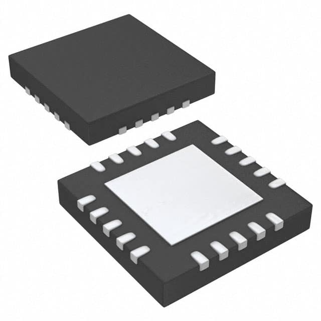
-
TSC2004IRTJR
Texas Instruments
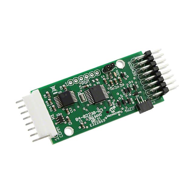
-
AR1100BRD
Microchip Technology
.jpg)
-
TSC2046IRGVR
Texas Instruments
Tech Hub

TTL and CMOS logic families differ in thresholds, loading, output drive, power and timing. This engineering guide compares 74HC and 74HCT, calculates noise margins and checks 3.3 V/5 V compatibility.

A practical engineering guide to 3.3V and 5V logic compatibility, input thresholds, resistor dividers, translator ICs, MOSFET level shifting, I2C pull-ups, timing limits and power-sequencing risks.

The 74HC595 uses push-pull logic outputs, while the TPIC6B595 uses 50 V open-drain DMOS sinks for higher-power loads. This guide compares timing, current limits, 3.3 V interfacing, load wiring, thermal…

The 74HC595 converts serial data into eight stable parallel outputs. This guide covers pin functions, shift and storage timing, OE and MR behavior, drive-current limits, cascading, voltage compatibilit…

A technical comparison of level-sensitive latches and edge-triggered flip-flops, covering timing windows, setup and hold limits, master–slave operation, time borrowing, race-through, HDL inference and…

A D latch stores one bit while Enable controls when data can pass. This reference covers gate-level operation, truth tables, transparency, setup and hold timing, LE versus OE, common ICs and practical …

An SR latch stores one bit through cross-coupled feedback. This engineering reference covers NOR and NAND implementations, truth tables, forbidden-state recovery, gated operation, switch debouncing, fa…

Latch circuits retain one bit through feedback. This technical reference covers SR and D latches, truth tables, transparency, timing limits, latch-versus-flip-flop behavior, applications and common log…

An engineering guide to LED driver operation, constant-current and constant-voltage outputs, linear and switching topologies, dimming, IC selection, calculations, replacement compatibility, and fault c…

Operational amplifier guide covering op amp basics, feedback, ideal vs real op amps, common configurations, buffer circuits, offset, bias current, gain-bandwidth, slew rate, rail-to-rail limits and sel…


