
 My Inquiry
 My Account


NXP Semiconductors MMA9559LKUBE
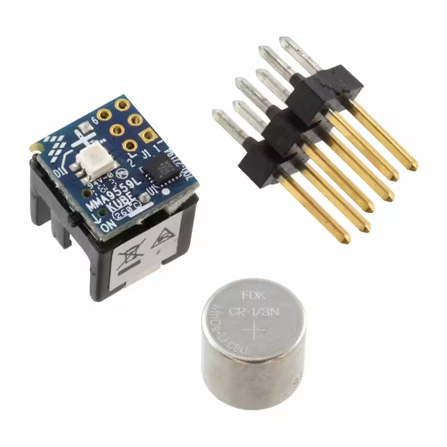
- Part No.:
- MMA9559LKUBE
- Manufacturer:
- NXP Semiconductors
- Category:
- Sensor Evaluation Boards
- Package:
- Datasheet:
-
 MMA9559LKUBE.pdf
- Description:
- MMA9559L CUBE DEMOBOARD
- Quantity:
- Payment:

- Shipping:

Inventory:4,980
Please send an inquiry. Send us your inquiry, and we will respond immediately.
Product details
Overview
MMA9559LKUBE from NXP Semiconductors (formerly Freescale) is an intelligent 3-axis motion-sensing platform integrating a MEMS accelerometer, 32-bit ColdFire V1 CPU, 16-KB flash, 2-KB RAM, and dual I²C interfaces (master + slave). It supports ±2/±4/±8 g ranges, 10–16-bit ADC resolution, and operates at 1.8 V. Designed for custom sensor fusion and real-time decision-making, it serves as an autonomous sensor hub in portable electronics requiring low-power, on-device processing.
For engineers reviewing the MMA9559LKUBE datasheet, MMA9559LKUBE pinout, MMA9559LKUBE application, or MMA9559LKUBE equivalent, this page delivers verified technical context, validated pin functions, confirmed firmware-specific capabilities (e.g., event management, inter-process FIFO), and two rigorously cross-checked alternative parts - all grounded in the official MMA955xL Rev. 3.1 datasheet and NXP product documentation.
Technical Context
The MMA9559LKUBE implements a dedicated mixed-signal ASIC with analog front-end (capacitance-to-voltage converter, temperature sensor, 16-bit ADC) tightly coupled to a 32-bit ColdFire V1 CPU featuring MAC unit and Background-Debug Module. Unlike fixed-function variants (MMA9551L/MMA9553L), it ships with Foundation firmware-no preloaded gesture or pedometer logic-requiring full user programming via CodeWarrior IDE v10.1+.
Its architecture enables true sensor hub operation: the master I²C (400 kbps) manages external sensors (gyros, magnetometers), while the slave I²C (7-bit address 0x4C default) or SPI interface (2 Mbps) communicates with host processors. Real-time scheduling is disabled; instead, it relies on programmable delay block (PDB), modulo timer, and TPM channels for deterministic event timing.
Key Specifications
| Parameter | Value and Actual Design Meaning |
|---|---|
| Accelerometer Range | ±2 g, ±4 g, ±8 g - selectable per application: ±2 g for tilt/orientation, ±4 g for walking/jogging, ±8 g for gaming/shock detection |
| ADC Resolution | 10/12/14/16-bit trimmed - higher bit depth enables precise low-g signal discrimination without external amplification |
| Output Data Rate | 3.8 Hz to 488 Hz (standard); extends to 0.24 Hz–3906 Hz with firmware update - supports ultra-low-power activity monitoring and high-speed gesture capture |
| Supply Voltage | 1.8 V (VDD/VDDA) - requires separate analog/digital power planes and tight bypassing (0.01–0.1 µF near each supply pin) |
| Memory | 16 KB flash (14 KB user-available), 2 KB RAM (1664 bytes user-available) - sufficient for custom control loops and multi-sensor fusion algorithms |
| I²C Interfaces | Slave I²C (up to 2 Mbps, 7-bit addr 0x4C), Master I²C (up to 400 kbps) - enables host communication + offloading of sensor initialization/calibration from AP |
| Power Modes | Deep-sleep, stop, doze - system-level power reduction via auto-wake/sleep disabled; user must implement state management in firmware |
Pinout & Package
16-pin LGA package (3 mm × 3 mm × 1 mm, Case 2094-01), RoHS-compliant, rated for –40°C to +85°C operation. Pin functions are multiplexed and configurable via SIM pin-mux registers after reset.
| Pin/Terminal | Circuit Role | Design Meaning |
|---|---|---|
| VDD / VSS / VDDA / VSSA | Digital/analog power and ground | Separate 1.8 V domains require independent bypassing and PCB plane isolation to prevent noise coupling into ADC/accelerometer signals |
| SCL0 / SDA0 | Slave I²C clock/data | Default interface to host processor; 7-bit address 0x4C; supports up to 2 Mbps - used for command/response and register access |
| SCL1 / SDA1 | Master I²C clock/data | Drives external sensors (e.g., magnetometers); 400 kbps max - enables calibration compensation and fused data acquisition without AP involvement |
| RGPIO4 / INT | Interrupt input | Level-7 priority wake-up source from deep-sleep; programmable edge/level trigger - connects to host MCU interrupt line for asynchronous event notification |
| RGPIO5 / PDB_A / INT_O | Programmable delay output / slave-port interrupt | INT_O outputs only COCO (conversion complete) interrupt; full interrupt routing requires RGPIO6–RGPIO9 - limits host notification scope unless remapped in firmware |
| BKGD-MS / RGPIO9 | Background-debug / mode select | Pulled high at startup for normal boot; pulled low for BDM entry - essential for firmware download/debug via single-wire interface |
Key Features
| Feature | Design Value |
|---|---|
| Event Management Engine | Hardware-accelerated event queue and inter-process FIFO - enables deterministic response to motion triggers (e.g., tap, freefall) without CPU polling overhead |
| Programmable Delay Block (PDB) | Two-channel scheduling relative to frame start - allows precise timing of sensor sampling, actuator activation, or communication bursts within sub-millisecond windows |
| Dual I²C Architecture | Independent master/slave controllers - eliminates need for host processor to manage secondary sensor initialization, reducing system latency and AP wake cycles |
| 16-bit Differential ADC | Converts external analog signals (e.g., pressure, battery voltage) synchronized to accelerometer ODR - supports sensor fusion without external ADC or timing alignment logic |
| Background-Debug Module (BDM) | Single-wire debug interface with flash/RAM access - enables in-system firmware updates and real-time variable inspection during motion algorithm development |
Applications
| Wearable Activity Tracker | Industrial Shock Monitor |
|---|---|
Use Scenario: Continuous motion logging in fitness bands with adaptive step counting and fall detection. IC Role / Device Role / Timing Role: Autonomous sensor hub performing real-time acceleration analysis, event classification, and buffered data streaming via slave I²C. Use Value: 14 KB user flash and 1664-byte RAM support custom activity classifiers; ±8 g range captures impact events; deep-sleep modes extend battery life beyond 7 days. | Use Scenario: Vibration and shock recording in fleet telematics units mounted in delivery vehicles. IC Role / Device Role / Timing Role: Standalone shock detector triggering wake-on-motion, timestamping high-g events, and storing raw acceleration data in internal FIFO. Use Value: Master I²C configures external temperature/pressure sensors; programmable PDB schedules periodic health checks; 1.8 V operation ensures compatibility with automotive LDOs. |
| Smart Home Appliance Safety | Medical Rehabilitation Sensor |
Use Scenario: Tilt-based safety shutoff in cordless power tools and robotic vacuum cleaners. IC Role / Device Role / Timing Role: Real-time orientation monitor using ±2 g range and embedded tilt-compensation algorithms. Use Value: On-chip temperature sensor corrects accelerometer drift; RGPIO outputs drive MOSFET gate drivers directly; no external MCU required for basic safety logic. | Use Scenario: Gait analysis and posture feedback in physical therapy wearables. IC Role / Device Role / Timing Role: High-precision motion engine capturing 16-bit acceleration data at 100 Hz with synchronized analog inputs (e.g., EMG). Use Value: 16-bit ADC resolves micro-motion artifacts; differential AN0/AN1 inputs reject common-mode noise; firmware-customizable filters suppress muscle tremor interference. |
Equivalent & Alternatives
The following parts are listed as comparable options for similar intelligent motion-sensing applications.
| Alternative Part | Technical Difference | Application Difference | Selection Advice |
|---|---|---|---|
| MMA9551LR1 | Preloaded gesture firmware; 4.5 KB user flash; no event management or inter-process FIFO | Out-of-box tap/portrait/tilt detection; no custom algorithm development required | Select when rapid time-to-market for consumer gesture UI is critical and firmware flexibility is secondary |
| BMI270 | Integrated gyroscope + accelerometer; 512-byte FIFO; native machine-learning core (Bosch Sensortec AI) | Higher integration reduces BOM count; ML core accelerates activity classification vs. CPU-based implementation | Select when sensor fusion (motion + rotation) and embedded ML inference are required, and 1.8 V dual-rail design is acceptable |
Compared with MMA9551LR1, the MMA9559LKUBE trades plug-and-play gesture features for full firmware control and larger memory - essential for proprietary algorithms. Versus BMI270, it lacks integrated gyro and ML hardware but offers greater ADC flexibility and deterministic PDB timing for hard real-time motion triggers.
Availability
MMA9559LKUBE is available at Aetrix Electronics and suitable for wearable activity trackers, industrial shock monitors, smart home appliance safety systems, medical rehabilitation sensors, and fleet telematics requiring stable component supply and long-term lifecycle support.
Supply support for MMA9559LKUBE includes scheduled delivery planning, volume procurement assistance, BOM continuity management, traceable sourcing, and lifecycle availability coordination for OEM customers, industrial embedded developers, connected-device designers, and electronics production programs.
Manufacturer
NXP Semiconductors is a global semiconductor leader focused on secure connectivity solutions for automotive, industrial, and IoT applications.
The MMA9559LKUBE belongs to NXP's intelligent motion-sensing platform family, designed specifically for applications demanding autonomous, low-power sensor processing - enabling host processors to remain in deep sleep until motion-derived decisions require system-level action.
FAQ
What firmware version ships on the MMA9559LKUBE, and how does it differ from other MMA955xL variants?
The MMA9559LKUBE ships with Foundation firmware - a blank-slate configuration containing no preloaded motion algorithms. Unlike MMA9551L (gesture) or MMA9553L (pedometer), it provides 14 KB user flash and 1664 bytes RAM for custom code. This enables full control over sensor fusion, event management, and real-time scheduling - but requires development with CodeWarrior IDE v10.1+. The MMA9559LKUBE firmware explicitly excludes real-time scheduling, slave port command interpreter, and front-end filtering blocks found in other variants.
Can the MMA9559LKUBE operate as both I²C master and slave simultaneously, and what are the timing constraints?
Yes, the MMA9559LKUBE supports concurrent master and slave I²C operation: slave I²C (SCL0/SDA0) runs up to 2 Mbps for host communication, while master I²C (SCL1/SDA1) operates up to 400 kbps for external sensor management. Critical timing constraints include strict power sequencing (VDD before VDDA), maximum 1.8 V supply tolerance, and mandatory external pull-up resistors (4.7 kΩ typical) on both buses. The master I²C cannot initiate transactions while the slave port is actively servicing a host command - arbitration is handled in hardware but requires firmware-level synchronization for fused data pipelines.
What are the valid ADC input configurations and resolution options for the MMA9559LKUBE?
The MMA9559LKUBE supports differential analog input across AN0(−) and AN1(+) pins, with 10-, 12-, 14-, or 16-bit trimmed resolution selectable in firmware. Input range is limited to ±1.8 V differential, synchronized to the same output data rate (ODR) as the accelerometer. The ADC cannot perform single-ended conversions or accept inputs exceeding the 1.8 V rail - external signal conditioning (e.g., instrumentation amplifier, level-shifting) is required for bipolar or higher-voltage sources. Calibration coefficients are stored in flash and applied automatically during conversion.
How does the programmable delay block (PDB) function in the MMA9559LKUBE, and what timing precision does it achieve?
The MMA9559LKUBE's PDB provides two independent channels (PDB_A, PDB_B) for scheduling events relative to the start of an acceleration data frame. It achieves sub-microsecond timing precision by leveraging the internal 32-bit CPU clock domain and supports output-triggered actions such as GPIO toggling, ADC sampling initiation, or interrupt generation. Unlike general-purpose timers, the PDB is optimized for deterministic, low-jitter synchronization with sensor data acquisition - critical for time-sensitive applications like impact detection or closed-loop haptic feedback where latency must be bounded below 10 µs.
Is the MMA9559LKUBE pin-compatible with other MMA955xL family members, and what layout considerations are unique to its Foundation firmware?
Yes, the MMA9559LKUBE shares identical 16-pin LGA packaging (3×3×1 mm, Case 2094-01) and pinout with MMA9550L/MMA9551L/MMA9553L. However, Foundation firmware imposes unique layout requirements: RGPIO3/SDA1/SSB must be pulled high externally to ensure I²C slave mode at boot (SPI mode requires active low), and BKGD-MS must be accessible for BDM debugging. Additionally, due to its full firmware development path, PCBs should include test points for VDDA/VSSA to minimize analog noise - especially critical when using the 16-bit ADC for precision external signal measurement alongside motion sensing.
MMA9559LKUBE Specifications
- Product attributes
- Attribute value
- Manufacturer:
- NXP Semiconductors
- Series:
- -
- Packaging:
- Box
- Product Status:
- Not For New Designs
- Sensor Type:
- Accelerometer, 3 Axis
- Sensing Range:
- ±2g, 4g, 8g
- Interface:
- -
- Sensitivity:
- 0.061mg/LSB, 0.122mg/LSB, 0.244mg/LSB
- Voltage - Supply:
- -
- Embedded:
- Yes, MCU, 32-Bit
- Contents:
- Board(s)
- Utilized IC / Part:
- MMA9559L
MMA9559LKUBE FAQ
1.How can I place an order for MMA9559LKUBE through Aetrix?
Please submit a Request for Quotation (RFQ) for MMA9559LKUBE on Aetrix. Our sales agent will provide a competitive quotation and guide you through the order confirmation once you accept the terms.
2.Are the price and stock information for MMA9559LKUBE reliable?
The price and inventory of MMA9559LKUBE are updated periodically and may fluctuate due to market conditions. Stock and pricing data are typically refreshed every 24 hours. Quotation validity for MMA9559LKUBE is usually 5 days.
3.What payment methods are accepted for MMA9559LKUBE?
We accept Wire Transfer, PayPal, Credit Card, Western Union, MoneyGram, and Escrow for MMA9559LKUBE transactions.
Note: Certain payment methods may incur a processing fee.
4.How is shipping managed for MMA9559LKUBE?
MMA9559LKUBE orders can be shipped via leading logistics carriers, including DHL, UPS, FedEx, TNT, or Registered Mail.
Once your MMA9559LKUBE order is processed, you will receive an email with the shipment details and tracking number.
Note: Tracking information may take up to 24 hours to appear. Express delivery typically takes 3–5 business days.
5.How can I obtain technical support or documentation for MMA9559LKUBE?
For technical support, including MMA9559LKUBE datasheets, pinout diagrams, or application guidance, please contact our engineering support team. They can provide detailed documentation and assistance for your MMA9559LKUBE requirements.
6.How does Aetrix verify that MMA9559LKUBE is sourced from the original manufacturer or authorized distributors?
All MMA9559LKUBE products on Aetrix are procured from qualified distributors and authorized channels. Our dedicated quality assurance team conducts strict verification, including traceability checks and, if necessary, third-party testing. This ensures that MMA9559LKUBE meets industry standards.
7.What is the process for return or replacement of MMA9559LKUBE?
All MMA9559LKUBE units undergo pre-shipment inspection (PSI). If there is an issue with MMA9559LKUBE, returns or replacements are accepted under the following conditions:
1.Quantity discrepancies, incorrect items, or visible external defects (such as breakage or corrosion), acknowledged by Aetrix.
2.The issue is reported within 90 days of delivery.
3.The MMA9559LKUBE part is unused and in its original packaging.
Return procedure for MMA9559LKUBE:
1.Submit a request within 90 days.
2.Obtain a Return Material Authorization (RMA) from Aetrix.
MMA9559LKUBE Tags
-
1782
Adafruit Industries LLC
-
SEN0142
DFRobot

-
2857
Adafruit Industries LLC
-
3316
Adafruit Industries LLC
-
2652
Adafruit Industries LLC
-
3317
Adafruit Industries LLC
-
163
Adafruit Industries LLC
-
SEN-09269
SparkFun Electronics
-
3709
Adafruit Industries LLC
-
1018
Adafruit Industries LLC
-
VL53L5CX-SATEL
STMicroelectronics
-
3387
Adafruit Industries LLC
Tech Hub

A practical engineering guide to 3.3V and 5V logic compatibility, input thresholds, resistor dividers, translator ICs, MOSFET level shifting, I2C pull-ups, timing limits and power-sequencing risks.

The 74HC595 uses push-pull logic outputs, while the TPIC6B595 uses 50 V open-drain DMOS sinks for higher-power loads. This guide compares timing, current limits, 3.3 V interfacing, load wiring, thermal…

The 74HC595 converts serial data into eight stable parallel outputs. This guide covers pin functions, shift and storage timing, OE and MR behavior, drive-current limits, cascading, voltage compatibilit…

A technical comparison of level-sensitive latches and edge-triggered flip-flops, covering timing windows, setup and hold limits, master–slave operation, time borrowing, race-through, HDL inference and…

A D latch stores one bit while Enable controls when data can pass. This reference covers gate-level operation, truth tables, transparency, setup and hold timing, LE versus OE, common ICs and practical …

An SR latch stores one bit through cross-coupled feedback. This engineering reference covers NOR and NAND implementations, truth tables, forbidden-state recovery, gated operation, switch debouncing, fa…

Latch circuits retain one bit through feedback. This technical reference covers SR and D latches, truth tables, transparency, timing limits, latch-versus-flip-flop behavior, applications and common log…

An engineering guide to LED driver operation, constant-current and constant-voltage outputs, linear and switching topologies, dimming, IC selection, calculations, replacement compatibility, and fault c…

Operational amplifier guide covering op amp basics, feedback, ideal vs real op amps, common configurations, buffer circuits, offset, bias current, gain-bandwidth, slew rate, rail-to-rail limits and sel…

Jumper cables guide covering safe connection order, red and black clamp placement, final ground connection, cable gauge, length, clamp quality, copper vs CCA cables, jump starter comparison and battery…


