
 My Inquiry
 My Account


Monolithic Power Systems Inc. MP2607DL-LF-P
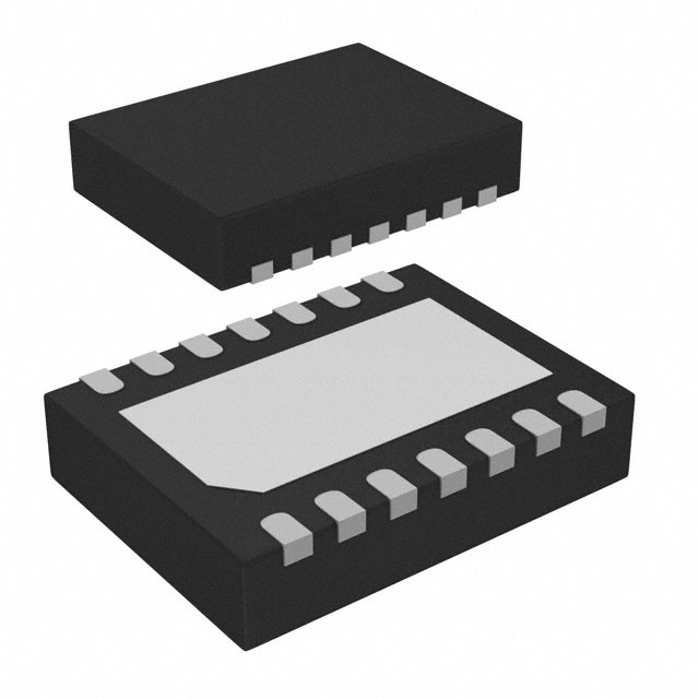
- Part No.:
- MP2607DL-LF-P
- Manufacturer:
- Monolithic Power Systems Inc.
- Category:
- Battery Chargers
- Package:
- 14-VFDFN Exposed Pad
- Datasheet:
-
 MP2607DL-LF-P.pdf
- Description:
- IC BATT CHG LI-ION 1CELL 14QFN
- Quantity:
- Payment:

- Shipping:

Inventory:1,494
Please send an inquiry. Send us your inquiry, and we will respond immediately.
Product details
Overview
MP2607DL-LF-P from Monolithic Power Systems is a fully autonomous linear Li-ion/Li-polymer battery charger IC with integrated system power path management. It supports dual-input selection (AC adapter or USB port), delivers up to 1.5 A programmable charge current, maintains ±0.75% CV voltage accuracy at 4.2 V, and features a 50 mΩ battery-to-system switch for instantaneous system power-up from deeply discharged batteries - used in portable handheld devices requiring simultaneous system operation and battery charging.
For engineers reviewing the MP2607DL-LF-P datasheet, MP2607DL-LF-P pinout, MP2607DL-LF-P application, or MP2607DL-LF-P equivalent, key selection criteria include input source selection logic (MODE pin), thermal fold-back threshold (105–135°C), programmable ICHG via external resistor (RCHG), end-of-charge current threshold (7–13% of ICHG), and power path behavior during system load surges exceeding input current limits.
Technical Context
The MP2607DL-LF-P implements a dual-path power architecture: an internal LDO regulates SYS from IN in AC mode (4.65–5.05 V), while a current-limited switch connects IN to SYS in USB mode (410–490 mA limit). Charging occurs via a P-channel FET (RON_BATT ≤ 400 mΩ) between IN and BATT, decoupling charge current from system load.
Power path control uses real-time arbitration: when ISYS + ICHG exceeds the input current limit, ICHG is reduced first; if SYS voltage drops below VBATT, a 50 mΩ N-channel switch (RON_BSW = 50–80 mΩ) engages to supplement system load from battery - enabling uninterrupted operation even with weak or current-limited sources.
Key Specifications
| Parameter | Value and Actual Design Meaning |
|---|---|
| Charging Voltage Accuracy | ±0.75% at 4.2 V - ensures battery stays within safe voltage window across –5°C to +75°C ambient. |
| Max Input Voltage | 12 V - supports low-cost, high-ripple AC adapters without external overvoltage protection. |
| USB Input Current Limit | 410–490 mA - enforces strict USB 2.0 compliance and prevents host port overload. |
| Battery-to-System RON | 50–80 mΩ - minimizes conduction loss during battery-supplement mode, extending runtime. |
| Thermal Fold-back Threshold | 105–135°C - dynamically reduces ICHG before thermal shutdown, preserving charge progress. |
| End-of-Charge Current | 7–13% of programmed ICHG - enables precise CC/CV termination without external sense resistors. |
| Trickle Charge Threshold | 2.7–2.9 V VBATT - initiates preconditioning for deeply discharged cells before full-rate charging. |
Pinout & Package
MP2607DL-LF-P is housed in a thermally enhanced QFN-14 package (3 mm × 4 mm, 0.5 mm pitch) with exposed thermal pad. The package supports high-power dissipation (θJA = 40°C/W on 4-layer board) and enables compact layout in space-constrained portable designs.
| Pin/Terminal | Circuit Role | Design Meaning |
|---|---|---|
| 1, 2 BATT | Battery terminal | Direct connection to single-cell Li-ion/Li-polymer anode/cathode; supports reverse-current blocking (1 µA leakage). |
| 3 MODE | Input source select | Logic-high = AC adapter mode (5.9 V OVP); logic-low = USB mode (6.27 V OVP); internal pull-up defaults to AC. |
| 4 ICHSET | Charge current programming | Connects to external resistor (RCHG) to set ICHG from 210 mA to 1.5 A using 1.26 V reference. |
| 5 TMR | Charge timer capacitor | Accepts CTMR (e.g., 1 µF = 1.1 hr at 1 A) to enforce safety timeout independent of EOC detection. |
| 6 CEB | Chip enable/battery-only mode | High (>2 V) disables IN regulation and charging; system powered solely by BATT via always-on 50 mΩ switch. |
| 7 GND | Power ground | Common return for IN, BATT, SYS paths; ties to exposed thermal pad for thermal performance. |
| 8 NTC | Battery temperature sense | Interfaces with NTC thermistor divider to halt charging outside safe temp range (0°C–50°C typical). |
| 9, 10 STAT2, STAT1 | Status indication | Open-drain outputs encoding 4 states: charging, EOC, suspend (battery supplement/NTC fault), or fault (thermal/time-out). |
| 11, 12 IN | Input power source | Accepts 4.51–12 V; internally routes to SYS regulator (AC) or current-limited switch (USB). |
| 13, 14 SYS | System power rail | Delivers regulated 4.85 V (AC) or VIN-derived voltage (USB); sourced from IN, BATT, or both simultaneously. |
Key Features
| Feature | Design Value |
|---|---|
| Autonomous power path arbitration | Real-time allocation of input current between system load and battery charge - no MCU intervention required. |
| Zero-downtime system startup | 50 mΩ BATT-to-SYS switch enables immediate SYS power-up even with 2.3 V battery voltage. |
| Programmable safety timers | External CTMR sets charge timeout (1.1–8.4 hr), preventing indefinite CV phase under fault conditions. |
| Integrated USB current limiting | Factory-trimmed 450 mA ±5% USB current limit eliminates need for external current-sense resistor. |
| Thermal-aware charge regulation | On-die temperature monitoring reduces ICHG before junction reaches 125°C, avoiding thermal shutdown cycles. |
Applications
| Smartphone Power Management | Digital Camera Battery System |
|---|---|
Use Scenario: Dual-input charging (USB-C or wall adapter) while camera remains operational during photo capture and video recording. IC Role / Device Role / Timing Role: MP2607DL-LF-P manages concurrent SYS power delivery and battery charging, dynamically sourcing current from IN or BATT based on load demand and input capability. Use Value: Eliminates system brownouts during high-current sensor/processor bursts by supplementing from battery - ensuring uninterrupted image capture and storage. | Use Scenario: Fast-charging Li-polymer battery in compact digital camera with USB-powered preview and flash charging. IC Role / Device Role / Timing Role: Acts as the primary battery charger and system power arbiter, enforcing USB current limits while maintaining 4.2 V ±0.75% float voltage for cell longevity. Use Value: Enables full USB compliance without derating - 450 mA USB limit is enforced internally, allowing direct connection to host PC without external current-limiting circuitry. |
| Handheld Test Equipment | Portable Medical Monitor |
Use Scenario: Field-deployable multimeter or oscilloscope running from battery while connected to USB for firmware updates and data logging. IC Role / Device Role / Timing Role: Provides seamless transition between USB-powered operation and battery backup; STATUS pins signal charge state to host MCU for UI feedback. Use Value: Maintains continuous instrument operation during USB disconnect events - battery supplements SYS within microseconds, avoiding measurement interruption. | Use Scenario: Battery-backed vital sign monitor that must remain active during AC adapter plug/unplug cycles and USB data export. IC Role / Device Role / Timing Role: Delivers regulated SYS rail and charges battery independently; NTC interface halts charging if battery temperature exceeds clinical safety thresholds. Use Value: Ensures uninterrupted patient monitoring by sustaining SYS voltage during input transients and enforcing medical-grade thermal safety via hardware-level NTC supervision. |
Equivalent & Alternatives
The following parts are listed as comparable options for similar Li-ion linear charger with power path applications.
| Alternative Part | Technical Difference | Application Difference | Selection Advice |
|---|---|---|---|
| BQ24075RGTR | Fixed 1 A charge current; no programmable ICHSET; 4.2 V CV accuracy ±0.5%; lacks thermal fold-back. | Requires external current-limiting for USB; no dynamic ICHG reduction under thermal stress - less robust in sealed enclosures. | Select when fixed-current, lower-cost solution suffices and thermal margin is ample. |
| TP4056 | No power path management; SYS not supported - only charges battery; no MODE/CEB control; no NTC interface. | Cannot power system during charge; requires separate LDO or DC-DC for SYS rail - increases BOM and PCB area. | Select only for cost-sensitive, non-system-power applications where battery charging is sole function. |
Compared with BQ24075RGTR and TP4056, MP2607DL-LF-P uniquely combines programmable charge current, hardware-enforced USB current limiting, and true power path arbitration - enabling smaller form factors, higher reliability under thermal load, and elimination of external current-sense or system power sequencing components.
Availability
MP2607DL-LF-P is available at Aetrix Electronics and suitable for smartphone power management, digital camera battery systems, handheld test equipment, and portable medical monitors requiring stable component supply, long-term lifecycle support, and RoHS-compliant packaging.
Supply support for MP2607DL-LF-P includes scheduled delivery planning, volume procurement assistance, BOM continuity management, traceable sourcing, and lifecycle availability coordination for OEM customers, industrial embedded developers, connected-device designers, and electronics production programs.
Manufacturer
Monolithic Power Systems (MPS) is a fabless semiconductor company specializing in high-performance analog and mixed-signal ICs for power management, motor drive, and automotive applications - with over 20 years of expertise in monolithic DC-DC conversion and battery solutions.
The MP2607 product line targets portable electronics requiring autonomous, space-efficient battery charging with zero-intervention power path control - designed specifically for applications where system uptime, battery health, and USB compliance must be guaranteed in a single chip.
FAQ
What is the maximum allowable input voltage for MP2607DL-LF-P, and how does overvoltage protection behave?
The absolute maximum input voltage is 13 V, but the device triggers overvoltage protection at 5.9 V in AC adapter mode and 6.27 V in USB mode. Recovery is automatic after input drops 260–310 mV below threshold. This allows use of unregulated 9 V or 12 V adapters while protecting internal circuitry from transient spikes without external TVS diodes.
How does MP2607DL-LF-P handle system load exceeding the USB current limit?
When ISYS exceeds 450 mA in USB mode, MP2607DL-LF-P first reduces or halts charging current. If SYS voltage then falls below VBATT, the 50 mΩ BATT-to-SYS switch activates to supplement load - maintaining SYS rail stability. This battery-supplement mode operates with constant-VDS control at low currents and transitions to constant-RDS at higher loads, preventing system reset.
Can MP2607DL-LF-P charge a battery while the system is powered off?
Yes - when CEB is pulled high (>2 V), the IN path and charger are disabled, but the BATT-to-SYS switch remains fully on, allowing battery to power SYS. However, charging is suspended. To charge while SYS is inactive, CEB must be low (<0.3 V) and a valid input source applied to IN; SYS can be left unconnected or lightly loaded.
What is the role of the TMR pin, and how is charge timeout calculated?
The TMR pin accepts an external capacitor (CTMR) to set a safety timeout - e.g., 1 µF yields 1.1 hours at 1 A ICHG. Timeout scales inversely with actual charging current, including reductions due to thermal fold-back or power path arbitration. The timer pauses when charging stops (e.g., during battery-supplement mode) and resets upon full charge, ensuring energy-based rather than time-based termination.
Does MP2607DL-LF-P support battery temperature monitoring, and how is it implemented?
Yes - the NTC pin interfaces with a resistor divider formed by the battery pack's NTC thermistor and two external resistors (RT1, RT2). MP2607DL-LF-P compares the resulting voltage against internal thresholds corresponding to user-defined high/low temperature limits. If out-of-range, charging halts immediately and STAT pins indicate "charge suspended", resuming automatically when temperature returns to safe bounds.
How accurate is the 4.2 V constant-voltage regulation, and over what conditions is it specified?
CV regulation accuracy is ±0.75% (4.179–4.221 V) at +25°C with zero battery load. Over –5°C to +75°C ambient and full load range, it degrades to ±0.83% (4.158–4.242 V). This specification includes process variation and temperature drift - critical for maximizing Li-ion cycle life and preventing overvoltage stress during field operation.
What happens to the SYS rail when the input source is removed during active charging?
Upon IN removal, MP2607DL-LF-P seamlessly transfers SYS supply from IN to BATT via the 50 mΩ switch - with no detectable dropout or glitch. The transition is hardware-controlled and occurs within microseconds, ensuring uninterrupted operation of connected processors, sensors, or displays. Battery voltage must exceed 2.3 V for this function to engage reliably.
MP2607DL-LF-P Specifications
- Product attributes
- Attribute value
- Manufacturer:
- Monolithic Power Systems Inc.
- Series:
- -
- Package/Case:
- 14-VFDFN Exposed Pad
- Packaging:
- Tape & Reel (TR)
- Product Status:
- Active
- Battery Chemistry:
- Lithium Ion/Polymer
- Number of Cells:
- 1
- Current - Charging:
- Constant - Programmable
- Programmable Features:
- Timer
- Fault Protection:
- Over Voltage
- Charge Current - Max:
- 1.5A
- Battery Pack Voltage:
- 4.2V
- Voltage - Supply (Max):
- 12V
- Interface:
- USB
- Operating Temperature:
- -40°C ~ 85°C (TA)
- Grade:
- -
- Qualification:
- -
- Mounting Type:
- Surface Mount
- Supplier Device Package:
- 14-QFN (3x4)
MP2607DL-LF-P FAQ
1.How can I place an order for MP2607DL-LF-P through Aetrix?
Please submit a Request for Quotation (RFQ) for MP2607DL-LF-P on Aetrix. Our sales agent will provide a competitive quotation and guide you through the order confirmation once you accept the terms.
2.Are the price and stock information for MP2607DL-LF-P reliable?
The price and inventory of MP2607DL-LF-P are updated periodically and may fluctuate due to market conditions. Stock and pricing data are typically refreshed every 24 hours. Quotation validity for MP2607DL-LF-P is usually 5 days.
3.What payment methods are accepted for MP2607DL-LF-P?
We accept Wire Transfer, PayPal, Credit Card, Western Union, MoneyGram, and Escrow for MP2607DL-LF-P transactions.
Note: Certain payment methods may incur a processing fee.
4.How is shipping managed for MP2607DL-LF-P?
MP2607DL-LF-P orders can be shipped via leading logistics carriers, including DHL, UPS, FedEx, TNT, or Registered Mail.
Once your MP2607DL-LF-P order is processed, you will receive an email with the shipment details and tracking number.
Note: Tracking information may take up to 24 hours to appear. Express delivery typically takes 3–5 business days.
5.How can I obtain technical support or documentation for MP2607DL-LF-P?
For technical support, including MP2607DL-LF-P datasheets, pinout diagrams, or application guidance, please contact our engineering support team. They can provide detailed documentation and assistance for your MP2607DL-LF-P requirements.
6.How does Aetrix verify that MP2607DL-LF-P is sourced from the original manufacturer or authorized distributors?
All MP2607DL-LF-P products on Aetrix are procured from qualified distributors and authorized channels. Our dedicated quality assurance team conducts strict verification, including traceability checks and, if necessary, third-party testing. This ensures that MP2607DL-LF-P meets industry standards.
7.What is the process for return or replacement of MP2607DL-LF-P?
All MP2607DL-LF-P units undergo pre-shipment inspection (PSI). If there is an issue with MP2607DL-LF-P, returns or replacements are accepted under the following conditions:
1.Quantity discrepancies, incorrect items, or visible external defects (such as breakage or corrosion), acknowledged by Aetrix.
2.The issue is reported within 90 days of delivery.
3.The MP2607DL-LF-P part is unused and in its original packaging.
Return procedure for MP2607DL-LF-P:
1.Submit a request within 90 days.
2.Obtain a Return Material Authorization (RMA) from Aetrix.
MP2607DL-LF-P Tags

-
BQ21040DBVR
Texas Instruments

-
MCP73812T-420I/OT
Microchip Technology
-
MCP73831T-2ACI/OT
Microchip Technology
-
MCP73832T-2ACI/OT
Microchip Technology
-
MCP73831T-2DCI/OT
Microchip Technology
-
MCP73832T-2DCI/OT
Microchip Technology
-
MCP73831T-2ATI/OT
Microchip Technology
-
MCP73832T-2ATI/OT
Microchip Technology
-
MCP73831T-5ACI/OT
Microchip Technology

-
MCP73832T-2ACI/MC
Microchip Technology
-
MCP73831T-2ACI/MC
Microchip Technology
-
MCP73831T-2ATI/MC
Microchip Technology
Tech Hub

Operational amplifier guide covering op amp basics, feedback, ideal vs real op amps, common configurations, buffer circuits, offset, bias current, gain-bandwidth, slew rate, rail-to-rail limits and sel…

Jumper cables guide covering safe connection order, red and black clamp placement, final ground connection, cable gauge, length, clamp quality, copper vs CCA cables, jump starter comparison and battery…

LDO regulator guide covering low dropout voltage, power dissipation, thermal design, PSRR, output noise, capacitor stability, adjustable LDO circuits, LDO vs buck converter and datasheet selection chec…

Conditional Access Module guide covering CAM meaning, CI/CI+ interface, smart card authorization, DVB security workflow, TV and set-top box compatibility, internal electronics, ESD protection, connecto…

Guide to electronic component obsolescence covering EOL risk, PCN/PDN notices, last-time buy planning, replacement options, form-fit-function validation, counterfeit risk and BOM lifecycle management.

18650 battery guide covering lithium-ion cell basics, 3.6V/3.7V voltage, 4.2V charging, mAh and Wh capacity, protected cells, chargers, BMS, series-parallel packs, holders, welding and sourcing checks.…

Hall effect sensor guide covering working principle, linear and digital sensors, Arduino circuits, current sensing, speed detection, automotive applications, A3144 examples, signal filtering and datash…

Product Change Notification guide for electronic components, covering PCN meaning, PCN vs PDN/EOL, common change types, risk levels, form-fit-function review, engineering validation, BOM control, LTB/L…

A practical guide to blend door actuators, covering HVAC function, symptoms, location, AC and heater issues, reset and calibration, replacement cost, electrical diagnosis, compatibility checks, and rep…

Engineering guide to Raspberry Pi alternatives, covering chip-level differences, Orange Pi, ROCK, Jetson, Banana Pi, NanoPi, Compute Module, Pico, GPIO, camera, HAT compatibility, and replacement risks…


