
 My Inquiry
 My Account


Monolithic Power Systems Inc. MP3214DQ-LF-Z
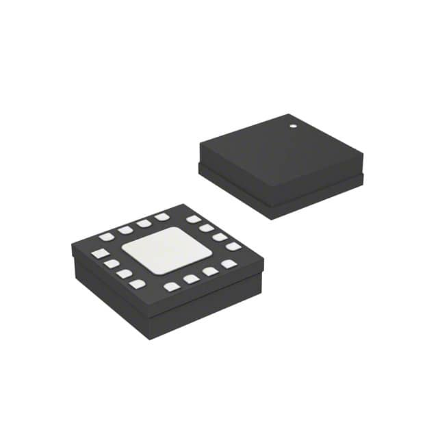
- Part No.:
- MP3214DQ-LF-Z
- Manufacturer:
- Monolithic Power Systems Inc.
- Category:
- LED Drivers
- Package:
- 16-VFQFN Exposed Pad
- Datasheet:
-
 MP3214DQ-LF-Z.pdf
- Description:
- IC LED DRIVER RGLTR 500MA 16QFN
- Quantity:
- Payment:

- Shipping:

Inventory:2,731
Please send an inquiry. Send us your inquiry, and we will respond immediately.
Product details
Overview
MP3214DQ-LF-Z from Monolithic Power Systems is a 500mA charge pump LED flash driver IC for camera modules, operating from 2.7V to 5.5V input and delivering programmable constant current up to 500mA via external RSET resistor. It features automatic gain switching (1X/1.5X/2X), PWM brightness control via EN pin, soft-start, open/short LED protection, and no inductor requirement. Used in smartphone camera flash circuits with tight space constraints.
For engineers reviewing the MP3214DQ-LF-Z datasheet, MP3214DQ-LF-Z pinout, MP3214DQ-LF-Z application, or MP3214DQ-LF-Z equivalent, key selection criteria include output current programmability (±8% gain accuracy), 1.35MHz fixed-frequency charge pump operation, thermal shutdown at 150°C, and QFN16 (3×3mm) package compatibility with handheld PCB layouts.
Technical Context
The MP3214DQ-LF-Z implements a switched-capacitor charge pump architecture with dynamically selectable voltage gain modes (1X, 1.5X, 2X) controlled by internal feedback to maintain LED forward voltage headroom across battery discharge (2.7–5.5V). It uses two external 1µF charge pump capacitors (C1, C2) and one 2.2µF bypass capacitor (CP).
Current regulation is achieved through ISET pin biasing with a precision external resistor (e.g., 17.8kΩ sets 202mA typical), while EN pin accepts 50Hz–2kHz PWM for analog-equivalent brightness control. TOE pin enables 1.55s post-enable timeout for flash duration extension without host MCU intervention.
Key Specifications
| Parameter | Value and Actual Design Meaning |
|---|---|
| Output Current | Up to 500mA programmable via RSET; ±8% gain accuracy ensures stable flash intensity across units. |
| Input Voltage Range | 2.7V to 5.5V; supports full Li-ion battery discharge curve without external LDO or buck pre-regulation. |
| Charge Pump Frequency | 1.35MHz fixed; enables use of small 1µF ceramic capacitors, minimizing board area and EMI. |
| Shutdown Current | 0.1µA; preserves battery life during standby in always-on camera subsystems. |
| LED Current Turn-On Delay | 4µs; meets fast-response requirements for burst-mode camera flash synchronization. |
| Thermal Shutdown Threshold | 150°C; protects die under sustained 500mA load in compact QFN16 package with θJA = 60°C/W. |
| EN Logic Thresholds | VIL = 0.75V, VIH = 0.81V; compatible with 1.8V/3.3V GPIO without level-shifting. |
Pinout & Package
MP3214DQ-LF-Z is housed in a thermally enhanced 16-pin QFN package (3mm × 3mm, 0.5mm pitch) with exposed thermal pad connected to GND (Pins 5 and 9). The package supports high-power dissipation (PDMAX = 2.1W at TA = 25°C) and requires JEDEC MO-220 VEED-4 compliant land pattern.
| Pin/Terminal | Circuit Role | Design Meaning |
|---|---|---|
| 1 CP | Charge pump bypass node | Connects to 2.2µF bypass capacitor; stabilizes internal charge pump reference and reduces noise on CP rail. |
| 2 C2B / 3 C1B / 4 C1A / 6 C2A | Charge pump capacitor terminals | Interface with two external 1µF ceramic caps (C1, C2); defines charge pump topology and voltage gain path. |
| 5,9 GND | Power ground & thermal pad connection | Primary return path for all currents; exposed pad must be soldered to PCB ground plane for thermal and electrical integrity. |
| 7 VIN | Main power input | Accepts 2.7–5.5V battery supply; requires ≥2.2µF local bypass capacitor to suppress input ripple. |
| 8 EN | Enable/PWM control input | Logic-level enable with 30ms shutdown delay; accepts 50Hz–2kHz PWM for precise flash brightness scaling. |
| 10 TOE | Timeout enable control | High = 1.55s flash hold time after EN deactivation; eliminates need for precise MCU timing in burst flash sequences. |
| 11 ISET | Current programming input | Connects to GND via RSET resistor; sets LED current per IOUT = 3570/RSET (kΩ), enabling factory-trimmed or software-adjustable flash intensity. |
| 14,15 IOUT | High-current LED driver outputs | Parallel 500mA sink outputs; connect common-cathode LED anode to battery and cathodes to IOUT pins for dual-LED flash configuration. |
| 12,13,16 NC | No-connect terminals | Unbonded or internally unused; must remain unconnected and un-routed to avoid parasitic coupling. |
Key Features
| Feature | Design Value |
|---|---|
| Automatic gain mode selection | Switches between 1X/1.5X/2X charge pump ratios in real time to maximize efficiency across 2.7–5.5V input range. |
| Open/short LED fault protection | Detects open-circuit or shorted LED strings and disables output to prevent overvoltage stress or thermal runaway. |
| Soft-start circuitry | Controls inrush current during power-up to limit input voltage droop and avoid false brown-out detection in shared battery rails. |
| No-inductor design | Eliminates magnetic components and associated EMI concerns, reducing BOM count and PCB footprint versus boost converter alternatives. |
| PWM brightness control via EN | Enables linear dimming using standard GPIO without requiring dedicated PWM peripheral or external transistor driver. |
Applications
| Smartphone Camera Flash | Tablet Dual-LED Torch |
|---|---|
Use Scenario: High-intensity brief illumination for auto-focus assist and low-light image capture in mobile phone rear/front cameras. IC Role / Device Role / Timing Role: Constant-current charge pump driver delivering up to 500mA peak current with <4µs turn-on delay for frame-synchronized flash triggering. Use Value: Enables consistent flash luminance across battery voltage range (2.7–4.2V) without brightness falloff or manual gain adjustment. | Use Scenario: Dual-white LED torch mode in tablets requiring steady 300–400mA output for extended illumination duration. IC Role / Device Role / Timing Role: Dual-channel current sink (Pins 14 & 15) driving parallel LEDs with matched current sharing and thermal foldback. Use Value: Eliminates need for discrete current-setting resistors per LED, reducing component count and improving current matching (<±8% gain accuracy). |
| Industrial Barcode Scanner Flash | USB-C Portable Camera Module |
Use Scenario: Short-duration, high-current pulse for barcode illumination in handheld scanners powered from USB or coin cell. IC Role / Device Role / Timing Role: Low-quiescent, fast-response flash controller with 0.1µA shutdown current and 1.35MHz switching for minimal capacitor size. Use Value: Supports compact form factor with only five external passive components (2×1µF, 1×2.2µF, 1×RSET, 1×bypass) and no inductor. | Use Scenario: Embedded camera module powered directly from USB-C 5V rail with strict EMI and space constraints. IC Role / Device Role / Timing Role: Inductorless charge pump providing regulated 500mA flash current while meeting CISPR-32 Class B conducted emissions limits. Use Value: Avoids magnetic field interference with nearby RF antennas and sensors due to absence of inductive energy storage. |
Equivalent & Alternatives
The following parts are listed as comparable options for similar LED flash driver applications.
| Alternative Part | Technical Difference | Application Difference | Selection Advice |
|---|---|---|---|
| RT9397BF | Fixed 400mA output; no RSET programmability; 1.2MHz switching frequency; requires larger 4.7µF charge pump caps. | Limited to single fixed-current setting; less flexible for multi-mode flash (torch vs. strobe) in same design. | Select when cost sensitivity outweighs current flexibility and board space is not constrained. |
| TPS61310DSKR | Inductor-based boost converter; 1.5A max output; wider 2.5–5.5V input; higher quiescent current (25µA vs. 0.1µA). | Better suited for high-voltage white LEDs (>3.6V VF) but introduces EMI and inductor footprint penalties. | Select when driving high-VF LEDs or when >500mA is required; avoid for ultra-low-power or EMI-sensitive camera modules. |
Compared with RT9397BF and TPS61310DSKR, MP3214DQ-LF-Z uniquely balances programmable current, ultra-low shutdown current, and inductorless operation-making it optimal for space-constrained, battery-sensitive camera flash systems requiring both torch and strobe modes.
Availability
MP3214DQ-LF-Z is available at Aetrix Electronics and suitable for smartphone camera flash, tablet LED torch, industrial barcode scanner illumination, and USB-C portable camera modules requiring stable component supply and RoHS-compliant packaging.
Supply support for MP3214DQ-LF-Z includes scheduled delivery planning, volume procurement assistance, BOM continuity management, traceable sourcing, and lifecycle availability coordination for OEM customers, industrial embedded developers, connected-device designers, and electronics production programs.
Manufacturer
Monolithic Power Systems (MPS) is a fabless semiconductor company specializing in high-performance analog and power ICs, with core expertise in DC/DC conversion, LED drivers, and motor control solutions.
The MP3214 belongs to MPS's LED flash driver product line, engineered specifically for compact, high-efficiency camera illumination in battery-powered portable devices where thermal density and solution size are critical.
FAQ
What is the maximum allowable RSET value for 100mA LED current?
The MP3214DQ-LF-Z uses the formula IOUT = 3570 / RSET (with RSET in kΩ). For 100mA output, RSET = 3570 / 100 = 35.7kΩ. The datasheet confirms 35.7kΩ yields 100mA typical, and the maximum recommended RSET is 35.7kΩ to ensure stable regulation within ±8% gain accuracy.
Can MP3214DQ-LF-Z drive multiple LEDs in series?
No - MP3214DQ-LF-Z is designed for common-anode configurations where LEDs connect anode-to-battery and cathode-to-IOUT pins. Its charge pump architecture provides voltage boosting below ground, not above VIN, so it cannot generate output voltages higher than the input rail. Series LED strings require a boost converter with positive voltage lift.
How does the TOE pin affect flash timing in burst photography?
When TOE = high, the device remains active for 1.55 seconds after EN goes low, allowing a single EN pulse to trigger a timed flash burst without continuous MCU intervention. This simplifies firmware timing for multi-frame capture and avoids race conditions between EN deassertion and LED current decay.
Is the exposed thermal pad electrically isolated?
No - the exposed pad on the QFN16 package is internally connected to GND (Pins 5 and 9). It must be soldered to a PCB copper pour tied to system ground for both thermal performance (θJC = 12°C/W) and electrical stability. Floating or insulated pads will cause overheating and functional failure.
Does MP3214DQ-LF-Z support analog dimming via ISET voltage?
No - ISET is a current-sense node that requires a resistor to GND; it does not accept analog voltage inputs. Brightness control is implemented exclusively via PWM on the EN pin or by changing RSET value. There is no DAC or analog voltage interface for dynamic current adjustment.
What happens during battery voltage drop from 4.2V to 2.7V?
The MP3214DQ-LF-Z automatically transitions from 1X (direct drive) to 1.5X to 2X charge pump gain to maintain constant LED current. At 4.2V, it operates in 1X mode; at ~3.3V, it switches to 1.5X; and below 3.0V, it engages 2X mode - all without external control or mode pin changes.
Are Pins 14 and 15 internally paralleled or independent?
Pins 14 and 15 are independent, matched current sinks with separate internal current mirrors. They share the same RSET programming but operate as two distinct 500mA-capable outputs - enabling dual-LED configurations with independent cathode routing and improved thermal distribution across the package.
MP3214DQ-LF-Z Specifications
- Product attributes
- Attribute value
- Manufacturer:
- Monolithic Power Systems Inc.
- Series:
- -
- Package/Case:
- 16-VFQFN Exposed Pad
- Packaging:
- Tape & Reel (TR)
- Product Status:
- Active
- Type:
- DC DC Regulator
- Topology:
- Switched Capacitor (Charge Pump)
- Internal Switch(s):
- Yes
- Number of Outputs:
- 1
- Voltage - Supply (Min):
- 2.7V
- Voltage - Supply (Max):
- 5.5V
- Voltage - Output:
- -
- Current - Output / Channel:
- 500mA (Flash)
- Frequency:
- 1.35MHz
- Dimming:
- -
- Applications:
- Backlight, Camera Flash
- Operating Temperature:
- -40°C ~ 85°C (TA)
- Grade:
- -
- Qualification:
- -
- Mounting Type:
- Surface Mount
- Supplier Device Package:
- 16-QFN (3x3)
MP3214DQ-LF-Z FAQ
1.How can I place an order for MP3214DQ-LF-Z through Aetrix?
Please submit a Request for Quotation (RFQ) for MP3214DQ-LF-Z on Aetrix. Our sales agent will provide a competitive quotation and guide you through the order confirmation once you accept the terms.
2.Are the price and stock information for MP3214DQ-LF-Z reliable?
The price and inventory of MP3214DQ-LF-Z are updated periodically and may fluctuate due to market conditions. Stock and pricing data are typically refreshed every 24 hours. Quotation validity for MP3214DQ-LF-Z is usually 5 days.
3.What payment methods are accepted for MP3214DQ-LF-Z?
We accept Wire Transfer, PayPal, Credit Card, Western Union, MoneyGram, and Escrow for MP3214DQ-LF-Z transactions.
Note: Certain payment methods may incur a processing fee.
4.How is shipping managed for MP3214DQ-LF-Z?
MP3214DQ-LF-Z orders can be shipped via leading logistics carriers, including DHL, UPS, FedEx, TNT, or Registered Mail.
Once your MP3214DQ-LF-Z order is processed, you will receive an email with the shipment details and tracking number.
Note: Tracking information may take up to 24 hours to appear. Express delivery typically takes 3–5 business days.
5.How can I obtain technical support or documentation for MP3214DQ-LF-Z?
For technical support, including MP3214DQ-LF-Z datasheets, pinout diagrams, or application guidance, please contact our engineering support team. They can provide detailed documentation and assistance for your MP3214DQ-LF-Z requirements.
6.How does Aetrix verify that MP3214DQ-LF-Z is sourced from the original manufacturer or authorized distributors?
All MP3214DQ-LF-Z products on Aetrix are procured from qualified distributors and authorized channels. Our dedicated quality assurance team conducts strict verification, including traceability checks and, if necessary, third-party testing. This ensures that MP3214DQ-LF-Z meets industry standards.
7.What is the process for return or replacement of MP3214DQ-LF-Z?
All MP3214DQ-LF-Z units undergo pre-shipment inspection (PSI). If there is an issue with MP3214DQ-LF-Z, returns or replacements are accepted under the following conditions:
1.Quantity discrepancies, incorrect items, or visible external defects (such as breakage or corrosion), acknowledged by Aetrix.
2.The issue is reported within 90 days of delivery.
3.The MP3214DQ-LF-Z part is unused and in its original packaging.
Return procedure for MP3214DQ-LF-Z:
1.Submit a request within 90 days.
2.Obtain a Return Material Authorization (RMA) from Aetrix.
MP3214DQ-LF-Z Tags

-
BCR402RE6327HTSA1
Infineon Technologies

-
BCR430UXTSA2
Infineon Technologies

-
BCR420UE6433HTMA1
Infineon Technologies
-
BCR420UE6327HTSA1
Infineon Technologies
-
BCR421UE6327HTSA1
Infineon Technologies

-
LYT1604D-TL
Power Integrations

-
HV9910CLG-G
Microchip Technology

-
CL2N8-G
Microchip Technology

-
BCR420UW6-7
Diodes Incorporated
-
BCR421UW6-7
Diodes Incorporated

-
BCR420UFD-7
Diodes Incorporated
-
BCR421UFD-7
Diodes Incorporated
Tech Hub

An engineering guide to LED driver operation, constant-current and constant-voltage outputs, linear and switching topologies, dimming, IC selection, calculations, replacement compatibility, and fault c…

Operational amplifier guide covering op amp basics, feedback, ideal vs real op amps, common configurations, buffer circuits, offset, bias current, gain-bandwidth, slew rate, rail-to-rail limits and sel…

Jumper cables guide covering safe connection order, red and black clamp placement, final ground connection, cable gauge, length, clamp quality, copper vs CCA cables, jump starter comparison and battery…

LDO regulator guide covering low dropout voltage, power dissipation, thermal design, PSRR, output noise, capacitor stability, adjustable LDO circuits, LDO vs buck converter and datasheet selection chec…

Conditional Access Module guide covering CAM meaning, CI/CI+ interface, smart card authorization, DVB security workflow, TV and set-top box compatibility, internal electronics, ESD protection, connecto…

Guide to electronic component obsolescence covering EOL risk, PCN/PDN notices, last-time buy planning, replacement options, form-fit-function validation, counterfeit risk and BOM lifecycle management.

18650 battery guide covering lithium-ion cell basics, 3.6V/3.7V voltage, 4.2V charging, mAh and Wh capacity, protected cells, chargers, BMS, series-parallel packs, holders, welding and sourcing checks.…

Hall effect sensor guide covering working principle, linear and digital sensors, Arduino circuits, current sensing, speed detection, automotive applications, A3144 examples, signal filtering and datash…

Product Change Notification guide for electronic components, covering PCN meaning, PCN vs PDN/EOL, common change types, risk levels, form-fit-function review, engineering validation, BOM control, LTB/L…

A practical guide to blend door actuators, covering HVAC function, symptoms, location, AC and heater issues, reset and calibration, replacement cost, electrical diagnosis, compatibility checks, and rep…


