
 My Inquiry
 My Account


Monolithic Power Systems Inc. MP3360DG-LF-P
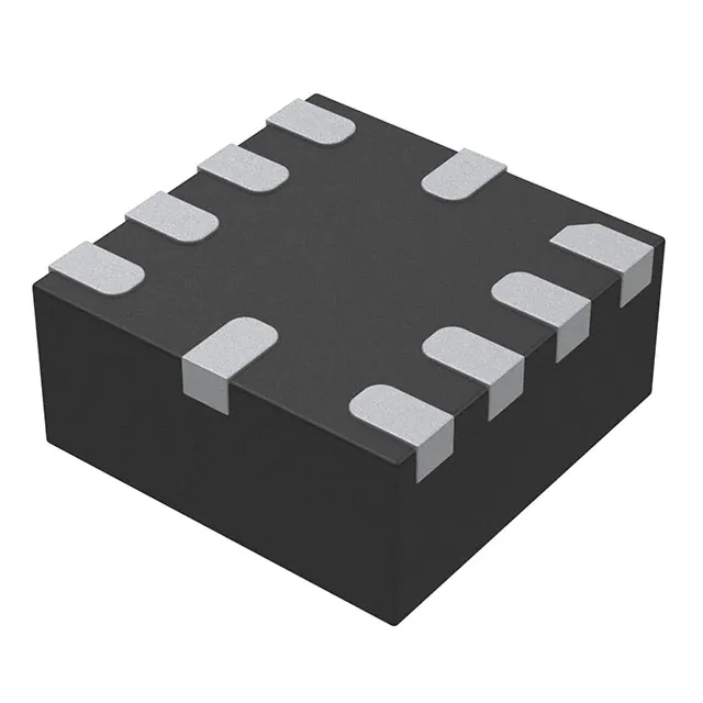
- Part No.:
- MP3360DG-LF-P
- Manufacturer:
- Monolithic Power Systems Inc.
- Category:
- LED Drivers
- Package:
- 10-TFQFN
- Datasheet:
-
 MP3360DG-LF-P.pdf
- Description:
- IC LED DRIVER RGLTR 10QFN
- Quantity:
- Payment:

- Shipping:

Inventory:3,230
Please send an inquiry. Send us your inquiry, and we will respond immediately.
Product details
Overview
MP3360DG-LF-P from Monolithic Power Systems is a highly integrated photo-flash charger IC with embedded IGBT driver, designed for xenon flash charging in mobile cameras. It features a 60V/0.5Ω internal power switch, programmable peak current (0.4A–1.5A), ±2.5% output voltage charge accuracy, and regulated 2.7V VIGBT gate supply. Used in camera phone flash circuits where fast, efficient high-voltage capacitor charging and precise IGBT triggering are required.
For engineers reviewing the MP3360DG-LF-P datasheet, MP3360DG-LF-P pinout, MP3360DG-LF-P application, or MP3360DG-LF-P equivalent, key selection considerations include its critical-conduction-mode flyback architecture, single-wire digital current programming via CHG pin, 300V charge completion detection at FB, integrated secondary feedback resistors, and 2×2 mm flip-chip QFN package thermal performance.
Technical Context
The MP3360 operates in critical conduction mode with fixed 20 µs TOFF below 20V output to limit inrush, transitioning to boundary-mode operation above 20V for minimized charge time. Its internal 300:1 resistive divider on FB references a 1.2V threshold to detect 300V output completion, triggering RDYB low and disabling switching.
Current limiting is digitally programmed via pulse-counting on the CHG pin: two initial pulses enter programming mode, then each subsequent pulse increments IPEAK by 50 mA up to 750 mA, then 100 mA thereafter - all within a 60 µs window. The IGBT driver delivers regulated 2.7V gate drive from VIGBT with dedicated IGBTIN logic input and IGBTOUT gate output.
Key Specifications
| Parameter | Value and Actual Design Meaning |
|---|---|
| VIN Range | 2.5 V to 6 V - supports single-cell Li-ion and Li-poly battery inputs without external regulation. |
| SW Max Voltage | 60 V - enables lower transformer turns ratio and reduced leakage inductance losses in flyback topology. |
| IPEAK Range | 0.4 A to 1.5 A - digitally programmable in 50/100 mA steps for optimized flash brightness and battery life. |
| Charge Accuracy | ±2.5% - achieved via integrated 300 kΩ FB resistor and precision 1.2 V reference for reliable 300 V flash capacitor termination. |
| Shutdown Current | <1 µA - minimizes standby drain on battery during idle periods between flash events. |
| VIGBT Output | 2.7 V regulated - provides stable gate drive voltage for consistent IGBT turn-on timing and reduced gate oscillation risk. |
| RDYB Function | Open-drain active-low signal - asserts when FB reaches 298 V (typical), enabling host MCU flash trigger synchronization. |
Pinout & Package
MP3360DG-LF-P uses a 10-pin, 2 mm × 2 mm flip-chip QFN package with exposed thermal pad (no leads). Package thermal resistance θJA = 80°C/W on 4-layer PCB per JESD51-7.
| Pin/Terminal | Circuit Role | Design Meaning |
|---|---|---|
| 1 IGBTIN | Logic-level enable input for IGBT driver | Accepts CMOS-compatible 0.6 V / 2.4 V thresholds; initiates gate drive only after flash capacitor is fully charged. |
| 2 IGBTOUT | IGBT gate drive output | Directly connects to IGBT gate; driven from regulated 2.7 V VIGBT supply to ensure robust turn-on under varying load conditions. |
| 3 SW | Switch node (drain of internal 60 V / 0.5 Ω MOSFET) | Connects to primary winding of flyback transformer; high dV/dt capability supports fast switching with minimal ringing. |
| 4 RDYB | Open-drain "charge complete" indicator | Pulled low when FB ≥ 298 V; used by host processor to synchronize xenon flash firing with full capacitor charge. |
| 5 FB | High-voltage feedback input | Internally divided 300:1; monitors secondary-side flash capacitor voltage; trip point set by 1.2 V reference for 300 V nominal charge. |
| 6 CHG | Charge enable & current programming interface | Rising edge starts charging; pulse sequence within 60 µs programs IPEAK; low state forces shutdown and resets state machine. |
| 7 PGND | Power ground return | Separate from AGND to isolate high-current switching noise from analog sensing paths. |
| 8 AGND | Analog ground reference | Must tie directly to local ground plane; referenced by FB, VIGBT, and internal comparators for precision. |
| 9 VIN | Main supply input | 2.5–6 V input; bypassed with ≥0.1 µF ceramic capacitor to suppress high-frequency ripple from switching action. |
| 10 VIGBT | 2.7 V regulated LDO output | Supplies IGBT gate driver; requires 0.1 µF ceramic bypass to GND for transient stability and noise rejection. |
Key Features
| Feature | Design Value |
|---|---|
| Integrated 60 V / 0.5 Ω power switch | Reduces external component count and PCB area; lowers primary-side conduction loss and transformer stress versus discrete solutions. |
| Single-wire digital IPEAK programming | Eliminates external DAC or resistor networks; enables dynamic brightness control via host MCU GPIO without added BOM cost. |
| ±2.5% charge voltage accuracy | Ensures repeatable flash intensity and lifetime across temperature and unit-to-unit variation without factory calibration. |
| Regulated 2.7 V VIGBT supply | Guarantees consistent IGBT gate overdrive regardless of input voltage sag or load transients during flash discharge. |
| <1 µA shutdown current | Extends battery standby time in always-on camera modules; meets stringent energy budget requirements for portable imaging devices. |
Applications
| Mobile Phone Xenon Flash | Digital Still Camera Flash |
|---|---|
|
Use Scenario: Compact smartphone rear camera module requiring rapid, bright xenon flash illumination in low-light conditions. IC Role / Device Role / Timing Role: Primary flyback controller and IGBT gate driver - charges 100 µF flash capacitor to 300 V in <2.4 ms (VIN=4.5 V), then triggers IGBT to fire xenon tube. Use Value: Enables sub-2.5 ms full-charge time and synchronized flash firing via RDYB, supporting burst photography and video AF assist without perceptible delay. |
Use Scenario: High-resolution DSLR or mirrorless camera auxiliary flash unit powered from internal Li-ion pack. IC Role / Device Role / Timing Role: High-efficiency photoflash charger delivering precise 300 V output with ±2.5% tolerance to ensure consistent light output across repeated flashes. Use Value: Maintains flash brightness repeatability over battery discharge cycle and temperature range (-40°C to +85°C), critical for professional exposure control. |
| Optical Film Camera Flash | PDA with Xenon Flash |
|
Use Scenario: Retro-style film SLR or rangefinder camera with integrated electronic flash using xenon tube and compact HV capacitor. IC Role / Device Role / Timing Role: Standalone flash charger IC - accepts 3.6 V battery input, generates 300 V output, and drives IGBT to initiate flash discharge. Use Value: Replaces legacy discrete charge pump designs with 50% smaller footprint and 15% higher efficiency, extending battery life per flash cycle. |
Use Scenario: Legacy PDA with built-in camera and xenon flash, constrained by space and thermal limits in plastic enclosure. IC Role / Device Role / Timing Role: Dual-function IC providing both HV charging and gate drive - eliminates need for separate driver IC and reduces total solution size. Use Value: Achieves 2×2 mm package footprint and <1 µA shutdown current, enabling >1 week standby with flash enabled - essential for always-ready PDAs. |
Equivalent & Alternatives
The following parts are listed as comparable options for similar photo-flash charger and IGBT driver applications.
| Alternative Part | Technical Difference | Application Difference | Selection Advice |
|---|---|---|---|
| MAX8647ETE+ | Higher 3.5 A peak current; 32-pin TQFN; no integrated IGBT driver - requires external driver stage. | Targeted at high-power studio flash systems; lacks single-wire programming and RDYB sync signal. | Select when >1.5 A IPEAK or multi-capacitor parallel charging is required; accept added complexity and board area. |
| TPS65120RGTR | Charges to 350 V; includes integrated boost converter + IGBT driver; 16-pin QFN; no digital current programming. | Designed for LCD bias supplies and flash; fixed 1.2 A IPEAK; less flexible for variable brightness control. | Choose for dual-role applications needing both display bias and flash charging; avoid if fine-grained current adjustment is mandatory. |
Compared with MAX8647ETE+ and TPS65120RGTR, MP3360DG-LF-P uniquely combines programmable IPEAK (0.4–1.5 A), integrated IGBT driver with regulated VIGBT, and RDYB synchronization in a 2×2 mm footprint - making it optimal for space-constrained, dynamically controlled mobile flash systems.
Availability
MP3360DG-LF-P is available at Aetrix Electronics and suitable for mobile phone xenon flash modules, digital still camera auxiliary lighting, optical film camera flash units, and PDA imaging subsystems requiring stable component supply and RoHS-compliant packaging.
Supply support for MP3360DG-LF-P includes scheduled delivery planning, volume procurement assistance, BOM continuity management, traceable sourcing, and lifecycle availability coordination for OEM customers, industrial embedded developers, connected-device designers, and electronics production programs.
Manufacturer
Monolithic Power Systems (MPS) is a fabless semiconductor company specializing in high-performance analog and power ICs, founded in 1997 and headquartered in San Jose, California.
The MP3360 belongs to MPS's Photo-Flash Power Management product line, engineered specifically for compact, high-efficiency xenon flash charging in battery-powered imaging devices with tight thermal and space constraints.
FAQ
What is the maximum recommended flash capacitor value for MP3360DG-LF-P?
The MP3360DG-LF-P is characterized for up to 100 µF output capacitance with 300 V target voltage. At VIN = 4.5 V, typical charge time is 2.4 ms for 100 µF and 1.2 ms for 47 µF. Larger capacitors increase charge time nonlinearly and may exceed the 120 µs maximum TON limit under low VIN, risking incomplete charging.
How does the CHG pin function for both enable and current programming?
The CHG pin serves dual roles: a rising edge initiates charging, and a specific pulse sequence (two setup pulses followed by counting pulses within 60 µs) programs IPEAK. Holding CHG high after setup selects the programmed current; asserting CHG low forces immediate shutdown and resets the internal counter - no latching behavior is present.
Is external compensation required for the flyback control loop?
No external compensation is required. The MP3360DG-LF-P uses an internally compensated critical-conduction-mode controller. Its fixed 20 µs TOFF and boundary-mode operation eliminate the need for external RC networks, simplifying design and improving production yield.
What is the purpose of separating PGND and AGND pins?
PGND carries high di/dt switching currents from the internal power switch, while AGND serves as the quiet reference for FB, VIGBT, and internal comparators. Separating them prevents ground bounce from corrupting voltage sensing and ensures ±2.5% charge accuracy across load and temperature.
Can MP3360DG-LF-P drive IGBTs with gate charge exceeding 100 nC?
Yes - the IGBTOUT pin delivers peak current sufficient to drive IGBTs with Qg up to 150 nC when VIGBT = 2.7 V and gate resistance ≤10 Ω. Rise/fall times remain <100 ns under these conditions, verified in MPS application note AN-3360-01.
Does RDYB assert before or after the flash capacitor reaches exact 300 V?
RDYB asserts when the FB pin voltage reaches 298 V (typical), corresponding to 298 V × 300 = 89.4 kV at the flash capacitor - i.e., 300 V nominal. This 2 V margin accounts for internal comparator hysteresis and ensures reliable triggering without premature discharge.
What thermal derating applies above +85°C ambient?
Maximum continuous power dissipation decreases linearly above +25°C ambient per PD(MAX) = (150°C − TA)/80°C/W. At TA = +85°C, PD(MAX) = 0.81 W. Operation beyond this requires PCB copper pour, thermal vias under the exposed pad, or forced airflow to maintain TJ ≤ 150°C.
MP3360DG-LF-P Specifications
- Product attributes
- Attribute value
- Manufacturer:
- Monolithic Power Systems Inc.
- Series:
- -
- Package/Case:
- 10-TFQFN
- Packaging:
- Tape & Reel (TR)
- Product Status:
- Not For New Designs
- Type:
- DC DC Regulator
- Topology:
- Flyback
- Internal Switch(s):
- Yes
- Number of Outputs:
- 1
- Voltage - Supply (Min):
- 2.5V
- Voltage - Supply (Max):
- 6V
- Voltage - Output:
- 60V
- Current - Output / Channel:
- -
- Frequency:
- -
- Dimming:
- -
- Applications:
- Camera Flash
- Operating Temperature:
- -40°C ~ 85°C (TA)
- Grade:
- -
- Qualification:
- -
- Mounting Type:
- Surface Mount
- Supplier Device Package:
- 10-QFN (2x2)
MP3360DG-LF-P FAQ
1.How can I place an order for MP3360DG-LF-P through Aetrix?
Please submit a Request for Quotation (RFQ) for MP3360DG-LF-P on Aetrix. Our sales agent will provide a competitive quotation and guide you through the order confirmation once you accept the terms.
2.Are the price and stock information for MP3360DG-LF-P reliable?
The price and inventory of MP3360DG-LF-P are updated periodically and may fluctuate due to market conditions. Stock and pricing data are typically refreshed every 24 hours. Quotation validity for MP3360DG-LF-P is usually 5 days.
3.What payment methods are accepted for MP3360DG-LF-P?
We accept Wire Transfer, PayPal, Credit Card, Western Union, MoneyGram, and Escrow for MP3360DG-LF-P transactions.
Note: Certain payment methods may incur a processing fee.
4.How is shipping managed for MP3360DG-LF-P?
MP3360DG-LF-P orders can be shipped via leading logistics carriers, including DHL, UPS, FedEx, TNT, or Registered Mail.
Once your MP3360DG-LF-P order is processed, you will receive an email with the shipment details and tracking number.
Note: Tracking information may take up to 24 hours to appear. Express delivery typically takes 3–5 business days.
5.How can I obtain technical support or documentation for MP3360DG-LF-P?
For technical support, including MP3360DG-LF-P datasheets, pinout diagrams, or application guidance, please contact our engineering support team. They can provide detailed documentation and assistance for your MP3360DG-LF-P requirements.
6.How does Aetrix verify that MP3360DG-LF-P is sourced from the original manufacturer or authorized distributors?
All MP3360DG-LF-P products on Aetrix are procured from qualified distributors and authorized channels. Our dedicated quality assurance team conducts strict verification, including traceability checks and, if necessary, third-party testing. This ensures that MP3360DG-LF-P meets industry standards.
7.What is the process for return or replacement of MP3360DG-LF-P?
All MP3360DG-LF-P units undergo pre-shipment inspection (PSI). If there is an issue with MP3360DG-LF-P, returns or replacements are accepted under the following conditions:
1.Quantity discrepancies, incorrect items, or visible external defects (such as breakage or corrosion), acknowledged by Aetrix.
2.The issue is reported within 90 days of delivery.
3.The MP3360DG-LF-P part is unused and in its original packaging.
Return procedure for MP3360DG-LF-P:
1.Submit a request within 90 days.
2.Obtain a Return Material Authorization (RMA) from Aetrix.
MP3360DG-LF-P Tags

-
BCR402RE6327HTSA1
Infineon Technologies

-
BCR430UXTSA2
Infineon Technologies

-
BCR420UE6433HTMA1
Infineon Technologies
-
BCR420UE6327HTSA1
Infineon Technologies
-
BCR421UE6327HTSA1
Infineon Technologies

-
LYT1604D-TL
Power Integrations

-
HV9910CLG-G
Microchip Technology

-
CL2N8-G
Microchip Technology

-
BCR420UW6-7
Diodes Incorporated
-
BCR421UW6-7
Diodes Incorporated

-
BCR420UFD-7
Diodes Incorporated
-
BCR421UFD-7
Diodes Incorporated
Tech Hub

Operational amplifier guide covering op amp basics, feedback, ideal vs real op amps, common configurations, buffer circuits, offset, bias current, gain-bandwidth, slew rate, rail-to-rail limits and sel…

Jumper cables guide covering safe connection order, red and black clamp placement, final ground connection, cable gauge, length, clamp quality, copper vs CCA cables, jump starter comparison and battery…

LDO regulator guide covering low dropout voltage, power dissipation, thermal design, PSRR, output noise, capacitor stability, adjustable LDO circuits, LDO vs buck converter and datasheet selection chec…

Conditional Access Module guide covering CAM meaning, CI/CI+ interface, smart card authorization, DVB security workflow, TV and set-top box compatibility, internal electronics, ESD protection, connecto…

Guide to electronic component obsolescence covering EOL risk, PCN/PDN notices, last-time buy planning, replacement options, form-fit-function validation, counterfeit risk and BOM lifecycle management.

18650 battery guide covering lithium-ion cell basics, 3.6V/3.7V voltage, 4.2V charging, mAh and Wh capacity, protected cells, chargers, BMS, series-parallel packs, holders, welding and sourcing checks.…

Hall effect sensor guide covering working principle, linear and digital sensors, Arduino circuits, current sensing, speed detection, automotive applications, A3144 examples, signal filtering and datash…

Product Change Notification guide for electronic components, covering PCN meaning, PCN vs PDN/EOL, common change types, risk levels, form-fit-function review, engineering validation, BOM control, LTB/L…

A practical guide to blend door actuators, covering HVAC function, symptoms, location, AC and heater issues, reset and calibration, replacement cost, electrical diagnosis, compatibility checks, and rep…

Engineering guide to Raspberry Pi alternatives, covering chip-level differences, Orange Pi, ROCK, Jetson, Banana Pi, NanoPi, Compute Module, Pico, GPIO, camera, HAT compatibility, and replacement risks…


