
 My Inquiry
 My Account


Monolithic Power Systems Inc. MP6510DM-LF
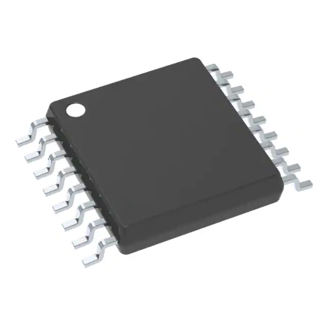
- Part No.:
- MP6510DM-LF
- Manufacturer:
- Monolithic Power Systems Inc.
- Category:
- Motor Drivers, Controllers
- Package:
- 16-TSSOP (0.173", 4.40mm Width)
- Datasheet:
-
 MP6510DM-LF.pdf
- Description:
- IC MOTOR DRIVER 4.5V-16V 16TSSOP
- Quantity:
- Payment:

- Shipping:

Inventory:2,564
Please send an inquiry. Send us your inquiry, and we will respond immediately.
Product details
Overview
MP6510DM-LF from Monolithic Power Systems is a single-phase brushless DC motor driver IC with integrated high-side (370 mΩ) and low-side (230 mΩ) MOSFETs, operating from 4.5V to 16V input and delivering up to 1.2A continuous output current. It implements Hall-sensor-based commutation, supports speed control via analog voltage or PWM on VTH, and integrates locked-rotor protection, thermal shutdown, input over-voltage protection (20V threshold), and 1.2V Hall bias regulation - deployed in CPU fan control for servers and desktops.
For engineers reviewing the MP6510DM-LF datasheet, MP6510DM-LF pinout, MP6510DM-LF application, or MP6510DM-LF equivalent, key selection criteria include its TSSOP16 package compatibility, Hall-input sensitivity down to 3mV differential, programmable minimum speed via RMI, FG/ RD open-collector status outputs, and dual-current-limit architecture (Hall-proportional + fixed 2.5A peak).
Technical Context
The MP6510DM-LF uses a Hall-sensor feedback loop to synchronize MOSFET switching across two drive paths (OUT1/OUT2), with commutation logic governed by amplified Hall differential inputs (IN+/IN−). Its oscillator frequency (26.4–35.6 kHz) is set externally via COSC capacitor, while CT pin controls locked-rotor recovery timing through charge/discharge current sources (ICT1 = 1.1–2.85 μA; ICT2 = 0.08–0.25 μA).
Speed regulation operates in four distinct modes-Minimum Speed, Variable Speed, Full-Speed, and Locked-Rotor Protection-determined by comparisons among VTH, RMI, and COSC ramp voltage. The device embeds dual protection layers: input OVP triggers HS-FET shutdown at 20V with 1.7V hysteresis, and thermal shutdown activates at ~175°C with automatic recovery at ~155°C.
Key Specifications
| Parameter | Value and Actual Design Meaning |
|---|---|
| Input Voltage Range | 4.5V to 16V - supports standard 5V/12V rail operation in PC/server cooling systems. |
| Max Continuous Output Current | 1.2A at TA = 25°C - defines thermal design margin for sustained fan motor drive without forced airflow. |
| HS/LS RDS(on) | 370 mΩ / 230 mΩ at VCC = 12V - determines conduction loss and junction temperature rise under load. |
| Hall Bias Voltage | 1.2V ±0.05V - powers external Hall sensors with stable low-noise reference, eliminating need for external bias supply. |
| Oscillator Frequency | 26.4–35.6 kHz (CP = 100 pF) - sets PWM switching rate to balance EMI, efficiency, and audible noise in fan applications. |
| Locked-Rotor Detection Threshold | Voltage on CT pin reaches 3.6V (VCTH) - triggers protection after fixed time determined by CT capacitor value and ICT1. |
| Quiescent Current | 1.4 mA (excluding Hall sensor) - enables low-power idle operation in thermally adaptive fan control loops. |
Pinout & Package
MP6510DM-LF is housed in a thermally enhanced 16-pin TSSOP package (5.0 mm × 6.4 mm), with exposed thermal pad connected to P-GND for improved heat dissipation. Pin numbering follows JEDEC MO-153 AB standard.
| Pin/Terminal | Circuit Role | Design Meaning |
|---|---|---|
| 1, 16 P-GND | Power Ground | Primary return path for motor current; must be low-impedance and tied to thermal pad for thermal management. |
| 2 OUT1 / 15 OUT2 | Motor Phase Outputs | Half-bridge terminals driving BLDC motor winding; polarity reversal enables bidirectional torque generation. |
| 3 VCC | Main Supply Input | Accepts 4.5–16V; powers internal regulators, gate drivers, and logic - requires ≥10 µF input capacitance for OVP margin. |
| 4 RMI | Minimum Speed Set | Analog input setting lowest allowable PWM duty cycle; connects to VTH if unused to disable min-speed clamp. |
| 5 VTH | Speed Control Input | Accepts 0–6V DC or PWM signal; directly modulates commutation timing to regulate motor RPM proportionally. |
| 6 COSC | Oscillator Timing | Connects to 100 pF capacitor to fix internal clock at ~30 kHz - critical for EMI compliance and gate drive timing. |
| 7 FG | Rotational Speed Indicator | Open-collector output pulsing at frequency proportional to motor RPM; requires external pull-up for logic-level interface. |
| 8 RD | Locked-Rotor Detector | Open-collector output pulled high during rotation; floats (Hi-Z) when rotor lock is detected - signals fault condition. |
| 9 IN+ / 11 IN− | Hall Sensor Differential Inputs | Accept ≥3 mV differential Hall signal; internal amplifier provides hysteresis and current-limit scaling (GC = 9 A/V). |
| 10 HB | Hall Bias Regulator | Stable 1.2V output sourcing up to 5 mA - powers external Hall ICs without external LDO or resistor divider. |
| 12 VREF | Internal Reference | 6V ±0.3V precision reference used for internal comparators and protection thresholds - not intended for external use. |
| 13 CT | Locked-Rotor Timer | Capacitor-connected node charged by ICT1 (1.1–2.85 μA); voltage crossing 3.6V initiates protection sequence. |
| 14 S-GND | Signal Ground | Separate ground return for Hall inputs, references, and logic - must be star-connected to P-GND near IC for noise immunity. |
Key Features
| Feature | Design Value |
|---|---|
| Integrated Half-Bridge Power Stage | Eliminates need for external MOSFETs and gate drivers - reduces BOM count and PCB area in compact fan modules. |
| Hall-Proportional Current Limit | Peak current scales linearly with Hall differential voltage (GC = 9 A/V), enabling dynamic torque limiting during commutation transitions. |
| Programmable Minimum Speed | RMI pin allows setting lowest operational duty cycle - prevents stalling at low ambient temperatures in server cooling profiles. |
| Dual-Stage Locked-Rotor Recovery | Automatic retry cycle (charge CT → detect lock → discharge CT → re-attempt) avoids manual reset and improves system reliability. |
| Built-in Input Over-Voltage Protection | Shuts down HS FETs at 20V input spike (1.7V hysteresis) - protects against inductive kickback during BLDC commutation. |
Applications
| CPU Fan Control | Server Chassis Cooling |
|---|---|
|
Use Scenario: Thermal management of multi-core CPUs in desktop PCs and workstations, where fan speed dynamically tracks die temperature. IC Role / Device Role / Timing Role: Motor driver IC providing Hall-synchronized commutation, speed regulation via VTH analog input, and real-time FG tachometer feedback. Use Value: Enables precise 0–100% RPM control with <3mV Hall sensitivity, reducing acoustic noise while maintaining thermal safety margins. |
Use Scenario: Redundant cooling in 1U/2U rack-mounted servers with multiple fans per chassis, requiring fault detection and graceful degradation. IC Role / Device Role / Timing Role: Single-chip BLDC driver with RD open-collector fault flag and automatic locked-rotor recovery to sustain airflow during partial failures. Use Value: Eliminates need for external watchdog circuitry; RD/FG outputs interface directly with BMC for telemetry and predictive maintenance. |
| Industrial Brushless Fans | Embedded System Cooling |
|
Use Scenario: Forced-air cooling in industrial PLC enclosures operating across -40°C to +85°C ambient range with variable dust loading. IC Role / Device Role / Timing Role: Robust motor controller with thermal shutdown (175°C), input OVP (20V), and wide 4.5–16V supply tolerance for unregulated DC rails. Use Value: Maintains operation under brownout and surge conditions common in factory power distribution, with automatic recovery post-fault. |
Use Scenario: Compact cooling solution for fanless-designed embedded gateways, edge AI accelerators, or medical imaging subsystems with strict size constraints. IC Role / Device Role / Timing Role: Integrated driver in TSSOP16 package (5.0×6.4mm) with exposed thermal pad - enables high-power density without heatsinks. Use Value: Reduces total footprint by >40% vs discrete MOSFET + gate driver solutions, supporting ultra-thin form factors. |
Equivalent & Alternatives
The following parts are listed as comparable options for similar single-phase BLDC motor driver applications.
| Alternative Part | Technical Difference | Application Difference | Selection Advice |
|---|---|---|---|
| ON Semiconductor MC33035 | Requires external N-channel MOSFETs; no integrated Hall bias or OVP; analog-only speed control (no PWM VTH support). | Lacks integrated protection features and Hall bias - demands additional components for server-grade reliability. | Select when legacy design reuse or discrete FET optimization is prioritized over integration and fault resilience. |
| Texas Instruments DRV10970 | Three-phase driver; supports sensorless (BEMF) and Hall modes; higher max current (2A); includes I²C configuration interface. | Over-specified for single-phase fans; adds complexity and cost where simple analog control suffices. | Prefer for multi-phase motors or designs requiring digital tuning - not drop-in compatible with MP6510DM-LF layout or pinout. |
Compared with MC33035 and DRV10970, MP6510DM-LF delivers optimal integration for cost-sensitive, single-phase fan applications - combining Hall bias, OVP, locked-rotor recovery, and analog/PWM speed control in one TSSOP16 package without requiring external FETs or configuration firmware.
Availability
MP6510DM-LF is available at Aetrix Electronics and suitable for CPU fan control, server chassis cooling, and industrial brushless fan applications requiring stable component supply, long-term lifecycle assurance, and RoHS-compliant packaging.
Supply support for MP6510DM-LF includes scheduled delivery planning, volume procurement assistance, BOM continuity management, traceable sourcing, and lifecycle availability coordination for OEM customers, industrial embedded developers, connected-device designers, and electronics production programs.
Manufacturer
Monolithic Power Systems (MPS) is a fabless semiconductor company specializing in high-performance power management ICs, with expertise in DC/DC converters, motor drivers, and LED controllers since 1997.
The MP6510 belongs to MPS's integrated BLDC motor driver product line, designed specifically for compact, reliable, and feature-rich cooling solutions in computing and industrial equipment - emphasizing Hall-based commutation, protection autonomy, and thermal robustness.
FAQ
What Hall sensor types are compatible with MP6510DM-LF?
The MP6510DM-LF supports bipolar latching Hall-effect sensors powered by its integrated 1.2V HB output. It accepts differential input sensitivity down to 3mV (IN+ − IN−), making it compatible with common 3-wire Hall ICs like Allegro A3291 or Melexis US5881. Unipolar or non-latching sensors are not supported due to required commutation phase detection.
How does the locked-rotor protection recover automatically?
Upon detecting no Hall transition for a time defined by CT capacitor and ICT1 current, the MP6510DM-LF disables PWM output and places RD in high-impedance state. ICT2 then discharges CT until voltage falls below VCTL (~1.73V), triggering automatic retry - repeating this cycle without external intervention until rotation resumes.
Can MP6510DM-LF drive motors requiring >1.2A continuous current?
No - its absolute maximum continuous output current is 1.2A at TA = 25°C with proper PCB copper area and thermal pad connection. Exceeding this risks thermal shutdown or permanent damage. For higher current, consider multi-phase alternatives like MP6530 or discrete half-bridge solutions with external FETs rated for the target load.
What is the purpose of separating P-GND and S-GND pins?
P-GND carries high di/dt motor return current and must be routed with low inductance to the thermal pad. S-GND serves as quiet reference for Hall inputs, VREF, and internal comparators. Separating them prevents noise coupling from power switching into sensitive analog circuits - essential for stable commutation and accurate current limiting.
Does MP6510DM-LF support PWM speed control on the VTH pin?
Yes - the VTH pin accepts either DC voltage (0–6V) or PWM signal (up to 30 kHz) to control motor speed. Internal filtering ensures stable operation with typical microcontroller PWM outputs; no external RC filter is required unless EMI mitigation is needed in noisy environments.
Is the exposed thermal pad electrically connected internally?
Yes - the exposed thermal pad is internally connected to P-GND and must be soldered to a large copper pour tied to P-GND. This connection is mandatory for both thermal performance (θJA = 90°C/W) and electrical stability, as it forms part of the main power return path for motor current.
What happens if the RMI pin is left floating?
Leaving RMI unconnected causes the device to default to full-speed mode - as RMI voltage drops below VTH, the driver bypasses minimum speed clamping and runs at 100% duty cycle. To avoid unintended full-speed operation, tie RMI to VTH (for disabled min-speed) or to a defined voltage divider for intentional minimum RPM setting.
MP6510DM-LF Specifications
- Product attributes
- Attribute value
- Manufacturer:
- Monolithic Power Systems Inc.
- Series:
- -
- Package/Case:
- 16-TSSOP (0.173", 4.40mm Width)
- Packaging:
- Tube
- Product Status:
- Active
- Motor Type - Stepper:
- -
- Motor Type - AC, DC:
- Brushless DC (BLDC)
- Function:
- Driver - Fully Integrated, Control and Power Stage
- Output Configuration:
- Half Bridge (2)
- Interface:
- Parallel
- Technology:
- Power MOSFET
- Step Resolution:
- -
- Applications:
- General Purpose
- Current - Output:
- 1.2A
- Voltage - Supply:
- 4.5V ~ 16V
- Voltage - Load:
- 4.5V ~ 16V
- Operating Temperature:
- -40°C ~ 125°C (TJ)
- Grade:
- -
- Qualification:
- -
- Mounting Type:
- Surface Mount
- Supplier Device Package:
- 16-TSSOP
MP6510DM-LF FAQ
1.How can I place an order for MP6510DM-LF through Aetrix?
Please submit a Request for Quotation (RFQ) for MP6510DM-LF on Aetrix. Our sales agent will provide a competitive quotation and guide you through the order confirmation once you accept the terms.
2.Are the price and stock information for MP6510DM-LF reliable?
The price and inventory of MP6510DM-LF are updated periodically and may fluctuate due to market conditions. Stock and pricing data are typically refreshed every 24 hours. Quotation validity for MP6510DM-LF is usually 5 days.
3.What payment methods are accepted for MP6510DM-LF?
We accept Wire Transfer, PayPal, Credit Card, Western Union, MoneyGram, and Escrow for MP6510DM-LF transactions.
Note: Certain payment methods may incur a processing fee.
4.How is shipping managed for MP6510DM-LF?
MP6510DM-LF orders can be shipped via leading logistics carriers, including DHL, UPS, FedEx, TNT, or Registered Mail.
Once your MP6510DM-LF order is processed, you will receive an email with the shipment details and tracking number.
Note: Tracking information may take up to 24 hours to appear. Express delivery typically takes 3–5 business days.
5.How can I obtain technical support or documentation for MP6510DM-LF?
For technical support, including MP6510DM-LF datasheets, pinout diagrams, or application guidance, please contact our engineering support team. They can provide detailed documentation and assistance for your MP6510DM-LF requirements.
6.How does Aetrix verify that MP6510DM-LF is sourced from the original manufacturer or authorized distributors?
All MP6510DM-LF products on Aetrix are procured from qualified distributors and authorized channels. Our dedicated quality assurance team conducts strict verification, including traceability checks and, if necessary, third-party testing. This ensures that MP6510DM-LF meets industry standards.
7.What is the process for return or replacement of MP6510DM-LF?
All MP6510DM-LF units undergo pre-shipment inspection (PSI). If there is an issue with MP6510DM-LF, returns or replacements are accepted under the following conditions:
1.Quantity discrepancies, incorrect items, or visible external defects (such as breakage or corrosion), acknowledged by Aetrix.
2.The issue is reported within 90 days of delivery.
3.The MP6510DM-LF part is unused and in its original packaging.
Return procedure for MP6510DM-LF:
1.Submit a request within 90 days.
2.Obtain a Return Material Authorization (RMA) from Aetrix.
MP6510DM-LF Tags

-
DRV2603RUNR
Texas Instruments

-
DRV8837CDSGR
Texas Instruments

-
DRV8837DSGR
Texas Instruments
-
DRV8838DSGR
Texas Instruments

-
DRV8839DSSR
Texas Instruments

-
EMC2301-1-ACZL-TR
Microchip Technology
-
DRV8231ADSGR
Texas Instruments

-
EMC2302-2-AIZL-TR
Microchip Technology

-
DRV8800PWPR
Texas Instruments
-
DRV8835DSSR
Texas Instruments

-
EMC2303-1-KP-TR
Microchip Technology

-
DRV8876PWPR
Texas Instruments
Tech Hub

Operational amplifier guide covering op amp basics, feedback, ideal vs real op amps, common configurations, buffer circuits, offset, bias current, gain-bandwidth, slew rate, rail-to-rail limits and sel…

Jumper cables guide covering safe connection order, red and black clamp placement, final ground connection, cable gauge, length, clamp quality, copper vs CCA cables, jump starter comparison and battery…

LDO regulator guide covering low dropout voltage, power dissipation, thermal design, PSRR, output noise, capacitor stability, adjustable LDO circuits, LDO vs buck converter and datasheet selection chec…

Conditional Access Module guide covering CAM meaning, CI/CI+ interface, smart card authorization, DVB security workflow, TV and set-top box compatibility, internal electronics, ESD protection, connecto…

Guide to electronic component obsolescence covering EOL risk, PCN/PDN notices, last-time buy planning, replacement options, form-fit-function validation, counterfeit risk and BOM lifecycle management.

18650 battery guide covering lithium-ion cell basics, 3.6V/3.7V voltage, 4.2V charging, mAh and Wh capacity, protected cells, chargers, BMS, series-parallel packs, holders, welding and sourcing checks.…

Hall effect sensor guide covering working principle, linear and digital sensors, Arduino circuits, current sensing, speed detection, automotive applications, A3144 examples, signal filtering and datash…

Product Change Notification guide for electronic components, covering PCN meaning, PCN vs PDN/EOL, common change types, risk levels, form-fit-function review, engineering validation, BOM control, LTB/L…

A practical guide to blend door actuators, covering HVAC function, symptoms, location, AC and heater issues, reset and calibration, replacement cost, electrical diagnosis, compatibility checks, and rep…

Engineering guide to Raspberry Pi alternatives, covering chip-level differences, Orange Pi, ROCK, Jetson, Banana Pi, NanoPi, Compute Module, Pico, GPIO, camera, HAT compatibility, and replacement risks…


