
 My Inquiry
 My Account


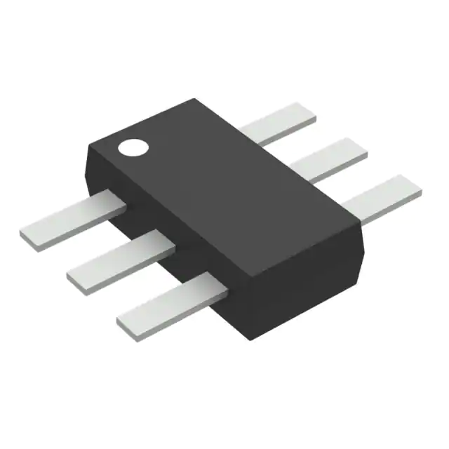
Monolithic Power Systems Inc. MP6517GJS-XXXX-P
- Part No.:
- MP6517GJS-XXXX-P
- Manufacturer:
- Monolithic Power Systems Inc.
- Category:
- Motor Drivers, Controllers
- Package:
- SOT-23-6 Thin, Flat Leads
- Datasheet:
-
 MP6517GJS-XXXX-P.pdf
- Description:
- SINGLE PHASE BLDC MOTOR DRIVER W
- Quantity:
- Payment:

- Shipping:

Inventory:2,375
Please send an inquiry. Send us your inquiry, and we will respond immediately.
Product details
Overview
MP6517GJS-XXXX-P from Monolithic Power Systems is a programmable single-phase BLDC motor driver IC with integrated Hall sensor, power MOSFETs (850 mΩ total RDS(on)), and reverse voltage protection. It delivers up to 1.2 A output current limit, operates from 3.3 V to 18 V, and provides programmable speed vs. PWM duty response for CPU fan control in servers and desktops.
For engineers reviewing the MP6517GJS-XXXX-P datasheet, MP6517GJS-XXXX-P pinout, MP6517GJS-XXXX-P application, or MP6517GJS-XXXX-P equivalent, key selection factors include its TSOT23-6-SL package, 26 kHz fixed switching frequency, soft on/off phase transition timing (1.45°–45°), rotor lock detection (0.6 s timeout), and I²C-capable FG/RD and PWM pins for register configuration.
Technical Context
The MP6517GJS-XXXX-P implements a Hall-based commutation controller with programmable θe delay (0°–15°) between Hall edge and current zero-crossing, enabling precise BEMF alignment. Its internal PLL locks to winding current zero-crossing during steady-state operation, reducing torque ripple and audible noise.
It integrates dual N-channel MOSFET half-bridge drivers (RHSON = 520 mΩ, RLSON = 330 mΩ), a 7 MHz oscillator, and OTP-programmable registers for startup current limit (320–1265 mA), soft-switching angles, and FG output scaling (1×/0.5×/2× Hall frequency). The FG/RD pin serves as open-drain speed indicator or rotor lock fault flag.
Key Specifications
| Parameter | Value and Actual Design Meaning |
|---|---|
| Input Voltage Range | 3.3 V to 18 V - supports wide-range DC input without external LDO; includes reverse voltage protection to eliminate external series diode. |
| Output Current Limit | Programmable up to 1.2 A - sets maximum motor drive capability; default SUCL = 860 mA for controlled spin-up. |
| Switching Frequency | Fixed 26 kHz - operates above audible range to suppress fan whine; independent of 12–48 kHz PWM input frequency. |
| Soft Transition Angle | 1.45° to 45° - configurable turn-on (SON_100/SOFTEN) and turn-off (SOFF_100) electrical angles reduce EMI and mechanical stress during phase switching. |
| Rotor Lock Detection | 0.6 s timeout - detects stalled rotor via missing Hall edges; triggers FG/RD low and auto-recovery after 1.8–3.6 s depending on RLOCK_SEL setting. |
| Thermal Shutdown | 150 °C with 25 °C hysteresis - disables H-bridge until die cools; enables automatic resumption without system reset. |
| FG Output Options | 1×, 0.5×, or 2× Hall frequency - selectable via FGRD[1:0] bits to match tachometer interface requirements across fan designs. |
Pinout & Package
MP6517GJS-XXXX-P is housed in a thermally enhanced TSOT23-6-SL package (0.95 mm height, 2.9 mm × 1.6 mm footprint), optimized for high-density fan module layouts and improved heat dissipation over standard TSOT23-6.
| Pin/Terminal | Circuit Role | Design Meaning |
|---|---|---|
| 1 GND | Power ground reference | Common return path for all internal circuits and motor current; must be low-impedance connection to minimize noise coupling. |
| 2 VCC | Main supply input | Accepts 3.3–18 V; includes reverse voltage protection and UVLO (3 V threshold) to prevent malfunction during brownout or miswiring. |
| 3 FG/RD/SCL | Open-drain multifunction pin | Outputs speed pulses (FG) or rotor lock flag (RD); functions as I²C SCL in test mode for register read/write via dedicated address 0xD0. |
| 4 PWM/SDA | PWM control input / I²C data | Accepts 12–48 kHz PWM signal to set target RPM; internal 100 kΩ pull-up enables direct MCU GPIO drive; doubles as I²C SDA in test mode. |
| 5 OUT2 | Half-bridge low-side output | Connects to motor winding midpoint; switches with complementary timing to OUT1 to generate rotating field; rated for continuous 1.2 A. |
| 6 OUT1 | Half-bridge high-side output | Drives motor winding opposite OUT2; shares same current-limit and thermal protection logic; forms complete N-MOSFET half-bridge with OUT2. |
Key Features
| Feature | Design Value |
|---|---|
| Integrated Hall sensor | High-sensitivity embedded cell (±1 mT min field) located at (540 µm, 508 µm, 80 µm) within package - eliminates external sensor placement calibration and reduces BOM count. |
| Programmable speed curve | 8-byte PWMO lookup table (0x00–0x08) stores linear or custom RPM vs. PWM duty mapping - enables precise airflow control across temperature and load variations. |
| Automatic phase-lock function | PLL synchronizes switching to winding BEMF zero-crossing using HA_OUT delay (THETA_E 0°–15°) - maintains optimal torque angle without external timing components. |
| Soft on/off transition | Configurable electrical angle ramp (SON_100/SOFF_100, 32-step resolution) - reduces acoustic noise and current overshoot during startup/shutdown. |
| OTP register configuration | Factory-programmable registers (0x09–0x0F) store SUCL, RPMS, RLOCK_SEL, and THETA_E - enables application-specific tuning without firmware changes. |
Applications
| CPU Fan Control | Server Chassis Cooling |
|---|---|
|
Use Scenario: Regulating rotational speed of 40–120 mm axial fans in x86-based servers under dynamic thermal load. IC Role / Device Role / Timing Role: Single-chip BLDC commutator with Hall feedback, PWM-to-RPM translation, and FG tachometer output. Use Value: Eliminates need for external gate drivers, Hall latches, and discrete protection devices-reducing PCB area by >35% versus discrete solutions. |
Use Scenario: Driving multiple 12 V brushless fans in redundant cooling modules with rotor lock detection and auto-recovery. IC Role / Device Role / Timing Role: Fault-tolerant motor driver with 0.6 s rotor lock timeout and programmable retry interval (1.8–3.6 s). Use Value: Prevents thermal runaway during fan stall events while maintaining system uptime via autonomous recovery-no host intervention required. |
| Embedded Industrial Fan | Network Equipment Thermal Management |
|
Use Scenario: Controlling compact 5 V–18 V fans in industrial HMIs and PLC enclosures operating from -40°C to +125°C junction. IC Role / Device Role / Timing Role: Integrated power stage with UVLO (3 V), OVP (19 V), and thermal shutdown (150 °C) for harsh environments. Use Value: Maintains stable operation across wide input transients and ambient extremes-no external protection circuitry needed. |
Use Scenario: Managing airflow in 1U/2U telecom switches where EMI-sensitive SerDes lanes require low-noise motor control. IC Role / Device Role / Timing Role: 26 kHz fixed-frequency driver with soft-switching angles (1.45°–45°) and 12–48 kHz PWM input compatibility. Use Value: Suppresses conducted EMI peaks near 10–50 MHz by eliminating variable-frequency jitter-meets CISPR 22 Class B limits. |
Equivalent & Alternatives
The following parts are listed as comparable options for similar single-phase BLDC motor driver applications.
| Alternative Part | Technical Difference | Application Difference | Selection Advice |
|---|---|---|---|
| MP6515GJS-Z | Lacks integrated Hall sensor; requires external Hall latch; identical TSOT23-6-SL package and 1.2 A current limit. | Suitable only when external Hall sensing is already present; no rotor lock detection or FG output. | Select when cost sensitivity outweighs integration benefit and Hall position is fixed externally. |
| DRV10970PWP | Texas Instruments part in HTSSOP-20; higher 2.5 A current rating but larger footprint; no OTP programming or soft-transition angle control. | Targets higher-power fans (>1.5 W); lacks programmable speed curve and rotor lock auto-recovery. | Choose for >1.5 A loads where board space allows larger package and register flexibility is secondary. |
Compared with MP6517GJS-XXXX-P, MP6515GJS-Z trades Hall integration for lower unit cost and simpler layout, while DRV10970PWP offers higher current headroom at the expense of programmability, acoustic optimization, and compactness-making MP6517GJS-XXXX-P optimal for space-constrained, noise-sensitive, and self-contained fan modules.
Availability
MP6517GJS-XXXX-P is available at Aetrix Electronics and suitable for CPU fan control, server chassis cooling, embedded industrial fan systems, and network equipment thermal management requiring stable component supply and long-term lifecycle support.
Supply support for MP6517GJS-XXXX-P includes scheduled delivery planning, volume procurement assistance, BOM continuity management, traceable sourcing, and lifecycle availability coordination for OEM customers, industrial embedded developers, connected-device designers, and electronics production programs.
Manufacturer
Monolithic Power Systems (MPS) is a fabless semiconductor company specializing in high-performance analog and power ICs, with design centers in the US, China, and Taiwan, and global manufacturing partnerships.
The MP6517 belongs to MPS's integrated motor driver product line, engineered specifically for compact, intelligent, and self-monitoring brushless DC fan applications in computing and communications infrastructure.
FAQ
What is the purpose of the THETA_E register (0x0F[3:0])?
The THETA_E register sets the electrical angle delay (0°–15°, 1° per step) between the raw Hall sensor edge and the generated HA_OUT signal used for commutation timing. This compensates for mechanical misalignment between the Hall sensor and motor poles, ensuring optimal BEMF-current phase alignment and maximizing torque efficiency.
Can MP6517GJS-XXXX-P drive a three-phase BLDC motor?
No. MP6517GJS-XXXX-P is strictly a single-phase BLDC driver with one half-bridge (OUT1/OUT2) and one integrated Hall sensor. It lacks the three-phase gate drive logic, Hall input channels, and commutation state machine required for three-phase motors. It is designed exclusively for single-coil axial fans.
How does the rotor lock detection recover after triggering?
Upon rotor lock detection (no Hall edge for 0.6 s), MP6517GJS-XXXX-P disables the H-bridge and pulls FG/RD low. After a programmable off-time (1.8–3.6 s, set by RLOCK_SEL bits), it automatically attempts restart. Recovery completes only after detecting three consecutive Hall edges, confirming rotor motion has resumed.
What is the role of the SUCL register (0x0A[2:0]) during fan startup?
The SUCL register configures the initial current limit during spin-up (320–1265 mA in 135 mA steps). The IC ramps this limit in 16 steps over ~250 ms to avoid inrush current, then holds the programmed value. This prevents stalling and ensures reliable start under static load or low-temperature conditions.
Is the FG/RD pin compatible with 5 V microcontrollers?
Yes. FG/RD is an open-drain output with 1 µA leakage and 0.35 V low-level voltage at 3 mA sink current. When pulled up to 5 V via an external resistor (e.g., 10 kΩ), it safely interfaces with 5 V logic without level-shifting, provided the pull-up voltage does not exceed VCC + 0.3 V.
Does MP6517GJS-XXXX-P support I²C write operations in normal operation?
No. I²C functionality (SCL/SDA on FG/RD and PWM pins) is only active in test mode, entered by applying a negative pulse to PWM with specific timing. In normal operation, those pins retain their primary functions (tach output/fault flag and PWM input), and registers are read-only unless re-entering test mode.
What thermal derating applies to the 1.25 W power dissipation rating?
The 1.25 W rating assumes TA = +25°C and θJA = 100°C/W on a 4-layer PCB (JESD51-7). At 85°C ambient, maximum continuous power drops to 0.85 W ((150 − 85)/100). Derating is linear; exceeding TJ = 150°C triggers thermal shutdown with 25°C hysteresis.
MP6517GJS-XXXX-P Specifications
- Product attributes
- Attribute value
- Manufacturer:
- Monolithic Power Systems Inc.
- Series:
- *
- Package/Case:
- SOT-23-6 Thin, Flat Leads
- Packaging:
- Tape & Reel (TR)
- Product Status:
- Active
- Motor Type - Stepper:
- -
- Motor Type - AC, DC:
- -
- Function:
- -
- Output Configuration:
- -
- Interface:
- -
- Technology:
- -
- Step Resolution:
- -
- Applications:
- -
- Current - Output:
- -
- Voltage - Supply:
- -
- Voltage - Load:
- -
- Operating Temperature:
- -
- Grade:
- -
- Qualification:
- -
- Mounting Type:
- Surface Mount
- Supplier Device Package:
- TSOT-23-6-SL
MP6517GJS-XXXX-P FAQ
1.How can I place an order for MP6517GJS-XXXX-P through Aetrix?
Please submit a Request for Quotation (RFQ) for MP6517GJS-XXXX-P on Aetrix. Our sales agent will provide a competitive quotation and guide you through the order confirmation once you accept the terms.
2.Are the price and stock information for MP6517GJS-XXXX-P reliable?
The price and inventory of MP6517GJS-XXXX-P are updated periodically and may fluctuate due to market conditions. Stock and pricing data are typically refreshed every 24 hours. Quotation validity for MP6517GJS-XXXX-P is usually 5 days.
3.What payment methods are accepted for MP6517GJS-XXXX-P?
We accept Wire Transfer, PayPal, Credit Card, Western Union, MoneyGram, and Escrow for MP6517GJS-XXXX-P transactions.
Note: Certain payment methods may incur a processing fee.
4.How is shipping managed for MP6517GJS-XXXX-P?
MP6517GJS-XXXX-P orders can be shipped via leading logistics carriers, including DHL, UPS, FedEx, TNT, or Registered Mail.
Once your MP6517GJS-XXXX-P order is processed, you will receive an email with the shipment details and tracking number.
Note: Tracking information may take up to 24 hours to appear. Express delivery typically takes 3–5 business days.
5.How can I obtain technical support or documentation for MP6517GJS-XXXX-P?
For technical support, including MP6517GJS-XXXX-P datasheets, pinout diagrams, or application guidance, please contact our engineering support team. They can provide detailed documentation and assistance for your MP6517GJS-XXXX-P requirements.
6.How does Aetrix verify that MP6517GJS-XXXX-P is sourced from the original manufacturer or authorized distributors?
All MP6517GJS-XXXX-P products on Aetrix are procured from qualified distributors and authorized channels. Our dedicated quality assurance team conducts strict verification, including traceability checks and, if necessary, third-party testing. This ensures that MP6517GJS-XXXX-P meets industry standards.
7.What is the process for return or replacement of MP6517GJS-XXXX-P?
All MP6517GJS-XXXX-P units undergo pre-shipment inspection (PSI). If there is an issue with MP6517GJS-XXXX-P, returns or replacements are accepted under the following conditions:
1.Quantity discrepancies, incorrect items, or visible external defects (such as breakage or corrosion), acknowledged by Aetrix.
2.The issue is reported within 90 days of delivery.
3.The MP6517GJS-XXXX-P part is unused and in its original packaging.
Return procedure for MP6517GJS-XXXX-P:
1.Submit a request within 90 days.
2.Obtain a Return Material Authorization (RMA) from Aetrix.
MP6517GJS-XXXX-P Tags

-
DRV2603RUNR
Texas Instruments

-
DRV8837CDSGR
Texas Instruments

-
DRV8837DSGR
Texas Instruments
-
DRV8838DSGR
Texas Instruments

-
DRV8839DSSR
Texas Instruments

-
EMC2301-1-ACZL-TR
Microchip Technology
-
DRV8231ADSGR
Texas Instruments

-
EMC2302-2-AIZL-TR
Microchip Technology

-
DRV8800PWPR
Texas Instruments
-
DRV8835DSSR
Texas Instruments

-
EMC2303-1-KP-TR
Microchip Technology

-
DRV8876PWPR
Texas Instruments
Tech Hub

A practical engineering guide to 3.3V and 5V logic compatibility, input thresholds, resistor dividers, translator ICs, MOSFET level shifting, I2C pull-ups, timing limits and power-sequencing risks.

The 74HC595 uses push-pull logic outputs, while the TPIC6B595 uses 50 V open-drain DMOS sinks for higher-power loads. This guide compares timing, current limits, 3.3 V interfacing, load wiring, thermal…

The 74HC595 converts serial data into eight stable parallel outputs. This guide covers pin functions, shift and storage timing, OE and MR behavior, drive-current limits, cascading, voltage compatibilit…

A technical comparison of level-sensitive latches and edge-triggered flip-flops, covering timing windows, setup and hold limits, master–slave operation, time borrowing, race-through, HDL inference and…

A D latch stores one bit while Enable controls when data can pass. This reference covers gate-level operation, truth tables, transparency, setup and hold timing, LE versus OE, common ICs and practical …

An SR latch stores one bit through cross-coupled feedback. This engineering reference covers NOR and NAND implementations, truth tables, forbidden-state recovery, gated operation, switch debouncing, fa…

Latch circuits retain one bit through feedback. This technical reference covers SR and D latches, truth tables, transparency, timing limits, latch-versus-flip-flop behavior, applications and common log…

An engineering guide to LED driver operation, constant-current and constant-voltage outputs, linear and switching topologies, dimming, IC selection, calculations, replacement compatibility, and fault c…

Operational amplifier guide covering op amp basics, feedback, ideal vs real op amps, common configurations, buffer circuits, offset, bias current, gain-bandwidth, slew rate, rail-to-rail limits and sel…

Jumper cables guide covering safe connection order, red and black clamp placement, final ground connection, cable gauge, length, clamp quality, copper vs CCA cables, jump starter comparison and battery…


