
 My Inquiry
 My Account


Monolithic Power Systems Inc. MP6527GF-Z
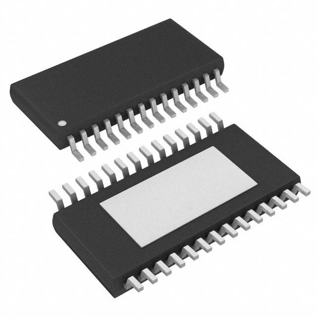
- Part No.:
- MP6527GF-Z
- Manufacturer:
- Monolithic Power Systems Inc.
- Category:
- Motor Drivers, Controllers
- Package:
- 28-TSSOP (0.173", 4.40mm Width) Exposed Pad
- Datasheet:
-
 MP6527GF-Z.pdf
- Description:
- 40V, 0.8A, 10-CHANNEL, HALF-BRID
- Quantity:
- Payment:

- Shipping:

Inventory:4,524
Please send an inquiry. Send us your inquiry, and we will respond immediately.
Product details
Overview
MP6527GF-Z from Monolithic Power Systems is a 10-channel, half-bridge motor driver IC with integrated DMOS power MOSFETs, serial SPI interface control, and comprehensive diagnostics. It delivers up to 0.8A per channel across 5.5V–40V supply range, features 1.3Ω typical RDS(ON) for HS/LS FETs, and operates in automotive and industrial motor control systems driving DC motors, solenoids, and valves.
For engineers reviewing the MP6527GF-Z datasheet, MP6527GF-Z pinout, MP6527GF-Z application, or MP6527GF-Z equivalent, key selection criteria include its 10 independent half-bridge topology, 5MHz SPI clock support, thermal pre-warning and shutdown thresholds (120°C/150°C), open-load detection with programmable shutdown, and dual VS1/VS2 power domains enabling flexible PCB layout in multi-motor modules.
Technical Context
The MP6527 implements a dual-domain power architecture: VS1 supplies drivers for channels 1,2,5,7,8 and internal LDO/charge pump; VS2 powers channels 3,4,6,9,10 - both must be externally tied. Its SPI interface uses CS-active-low framing, DI data latched on CLK falling edge, and DO output enabled on CS falling edge with PRE_15 thermal latch bit.
Each half-bridge supports independent high-side-on / low-side-on configuration via 16-bit input registers, with diagnostic feedback including latched over-current (OC), open-load (OLD), thermal warning (TW), and power supply failure (PSF) bits returned via DO. Faults persist until cleared by Status Register Reset (SRR), EN toggle, or VCC power-on reset.
Key Specifications
| Parameter | Value and Actual Design Meaning |
|---|---|
| VIN Range | 5.5V to 40V - supports 12V/24V/36V automotive and industrial battery rails without external regulators. |
| Output Current | 0.8A continuous per channel - sufficient for small DC motors, stepper coil phases, and solenoid actuation. |
| RDS(ON) | 1.3Ω typical (HS + LS) - limits conduction loss to ≤0.83W per channel at 0.8A, easing thermal design. |
| SPI Clock | Up to 5MHz - enables sub-100μs register update latency for real-time motor commutation control. |
| Thermal Protection | 120°C pre-warning + 150°C shutdown - provides early fault indication while maintaining operation until critical junction temperature. |
| Open-Load Detection | 1–45mA threshold with 200–600μs delay - identifies disconnected loads before startup or during runtime without external sensing. |
| Quiescent Current | 1–5μA in EN-low standby - enables always-on microcontroller wake-up capability in low-power systems. |
Pinout & Package
TSSOP-28EP package with exposed thermal pad on bottom for enhanced heat dissipation; pin-compatible with industry-standard TSSOP-28 footprint but requires solder paste stencil optimization for thermal pad reflow.
| Pin/Terminal | Circuit Role | Design Meaning |
|---|---|---|
| OUT1–OUT10 | Half-bridge outputs | 10 independent source/sink terminals; each drives one motor winding, solenoid, or valve coil in H-bridge mode. |
| VS1, VS2 | Power supply inputs | VS1 powers channels 1,2,5,7,8; VS2 powers channels 3,4,6,9,10 - must be externally shorted for single-rail use. |
| DI, DO, CLK, CS | SPI interface signals | Standard 4-wire SPI: DI accepts 16-bit command frames; DO returns 16-bit status + PRE_15 latch bit on CS falling edge. |
| EN | Enable control | Pull low to disable all outputs and enter 1–5μA standby; internal pull-down eliminates external resistor. |
| GND (Pins 2,13,16,27) | Ground reference | Four dedicated GND pins reduce ground bounce and improve noise immunity in high-current switching. |
| VCC | Logic supply | 3.15–5.25V logic rail - compatible with 3.3V or 5V MCU I/O without level shifters. |
| TEST (Pins 20,21) | Internal test node | Must be connected to GND per datasheet; not for user functionality or signal routing. |
| NC (Pins 1,14,15,28) | No connection | Unbonded die pads - leave unconnected and unrouted on PCB. |
Key Features
| Feature | Design Value |
|---|---|
| Dual VS domain architecture | Enables independent power routing for grouped motor channels, reducing trace congestion and improving EMI performance. |
| Latched diagnostic reporting | OC, OLD, PSF, and TW faults remain asserted until SRR command or reset - ensures no fault is missed in interrupt-driven firmware. |
| Programmable open-load shutdown | OLSD_EN bit allows selective disabling of affected outputs upon open-load detection - prevents system lockup while preserving healthy channels. |
| Thermal pre-warning flag | TW bit asserts at 120°C (typical), giving firmware 30°C margin to throttle load or trigger cooling before 150°C shutdown. |
| 5V/3.3V logic compatibility | Input thresholds (0.6V/2.0V) and output levels (0.4V low / VCC−0.6V high) work natively with both voltage domains - eliminates level-shifter BOM cost. |
Applications
| Automotive HVAC Actuators | Industrial PLC Output Modules |
|---|---|
Use Scenario: Controlling blend door, mode door, and recirculation flaps in vehicle climate systems using 10–30W DC motors. IC Role / Device Role / Timing Role: 10-channel half-bridge driver with serial command interface replaces discrete H-bridge arrays and reduces MCU GPIO count by >80%. Use Value: Integrated open-load detection confirms motor connection integrity before movement, preventing erroneous position feedback and field failures. | Use Scenario: Driving 24V solenoid valves, indicator lamps, and small pumps in modular industrial I/O racks. IC Role / Device Role / Timing Role: Serial-controlled motor driver providing isolated, protected, and diagnosable outputs from a single 28-pin package. Use Value: Latched over-current and thermal shutdown prevent cascade failures when multiple outputs share common 24V bus under overload conditions. |
| Medical Infusion Pump Motor Control | Robotics Joint Actuation |
Use Scenario: Precision control of peristaltic pump rollers and syringe drive mechanisms requiring bidirectional torque and stall detection. IC Role / Device Role / Timing Role: Half-bridge driver executing microstepping-like current direction sequencing via SPI register writes synchronized to MCU timing. Use Value: 5MHz SPI interface enables <100μs command-to-output latency, supporting closed-loop speed regulation at ≥1kHz update rates. | Use Scenario: Driving small DC gearmotors in collaborative robot end-effectors and sensorized joints where space and diagnostics are critical. IC Role / Device Role / Timing Role: Compact 10-output motor driver enabling distributed actuation with per-channel fault visibility over shared SPI bus. Use Value: Dual VS1/VS2 domains allow separate power routing to motor groups - simplifying thermal management and reducing crosstalk in dense PCB layouts. |
Equivalent & Alternatives
The following parts are listed as comparable options for similar 10-channel half-bridge motor driver applications.
| Alternative Part | Technical Difference | Application Difference | Selection Advice |
|---|---|---|---|
| TB9051FTG | 8-channel, 3.0A/channel, CAN FD interface, built-in current sense - higher current, lower channel count, automotive CAN-native protocol. | Requires CAN controller MCU; lacks open-load detection; targets safety-critical steering/braking vs. HVAC/valve control. | Select when CAN integration and >1A per channel are mandatory; avoid if SPI simplicity and 10-channel density are primary. |
| DRV8876N | 2-channel, 3.6A/channel, PWM-input only, no serial interface or diagnostics - simpler control, no fault reporting, no multi-channel integration. | Needs external logic/MCU GPIO for channel expansion; no SPI register access or latched diagnostics. | Select for cost-sensitive, low-channel-count applications where diagnostics and serial control are unnecessary. |
Compared with TB9051FTG and DRV8876N, MP6527GF-Z uniquely balances 10-channel integration, SPI configurability, full diagnostic latching, and 0.8A capability in a compact TSSOP-28EP - making it optimal for space-constrained, multi-actuator systems requiring deterministic fault handling without CAN infrastructure.
Availability
MP6527GF-Z is available at Aetrix Electronics and suitable for automotive HVAC actuators, industrial PLC output modules, medical infusion pump motor control, and robotics joint actuation requiring stable component supply across extended production lifecycles.
Supply support for MP6527GF-Z includes scheduled delivery planning, volume procurement assistance, BOM continuity management, traceable sourcing, and lifecycle availability coordination for OEM customers, industrial embedded developers, connected-device designers, and electronics production programs.
Manufacturer
Monolithic Power Systems (MPS) is a fabless semiconductor company specializing in high-performance power management ICs, with design centers in the US, China, and Taiwan, and global distribution since 1997.
The MP65xx series targets high-channel-count motor control in space- and reliability-constrained environments, emphasizing serial configurability, integrated protection, and diagnostic transparency for automotive and industrial applications.
FAQ
What is the maximum allowable voltage on the VS pins, and what happens above that limit?
The absolute maximum VS supply voltage is 45V. Exceeding this rating risks permanent damage to internal DMOS transistors and gate drivers. The device includes over-voltage lockout (OVLO) that triggers at 33–39V (typical 36V) to disable outputs before reaching 45V, but sustained exposure above 45V voids reliability guarantees and may cause immediate failure.
How does the open-load detection (OLD) function interact with the OLSD_EN bit?
When OLSD_EN is set to 1, detected open-load conditions (current <1–45mA for >200–600μs) force the corresponding half-bridge into Hi-Z state and latch the OLD bit. If OLSD_EN = 0, the OLD bit still asserts but the output remains active. Both modes require SRR or reset to clear the latched bit - the bit does not auto-clear when load is restored.
Can MP6527GF-Z drive inductive loads without external flyback diodes?
Yes - the integrated DMOS half-bridges include body diodes capable of clamping inductive kickback during turn-off. No external flyback diodes are required for standard DC motor or solenoid loads within the 0.8A/40V ratings. However, layout must minimize loop inductance, and thermal design must account for energy dissipated in RDS(ON) during freewheeling.
What is the purpose of the PRE_15 bit on the DO line, and how is it read?
PRE_15 is the latched thermal shutdown (TSD) status bit, asserted when junction temperature reaches 150°C. It appears as the MSB of the 16-bit DO response immediately after CS falls, and remains valid until the first rising CLK edge post-CS-fall. It is not part of the main status register and cannot be cleared by SRR - only by power cycle or EN toggle.
Is the TSSOP-28EP package RoHS-compliant and lead-free?
Yes - MP6527GF-Z is fully RoHS-compliant, lead-free, and halogen-free per MPS green policy. The TSSOP-28EP package uses matte tin lead finish and meets JEDEC J-STD-020 moisture sensitivity level 2A, requiring dry pack storage and assembly within 1 year of seal opening unless baked.
How does the dual VS1/VS2 supply architecture affect PCB layout and thermal design?
VS1 and VS2 must be externally shorted with low-inductance copper; splitting them violates internal biasing and causes malfunction. The exposed thermal pad requires ≥70% solder coverage and connection to a solid internal ground plane for θJA = 32°C/W. Thermal vias under the pad (≥8×0.3mm) are mandatory for >0.5A continuous operation per channel.
What is the minimum pulse width required on the EN pin to ensure reliable wake-up from standby?
The EN pin must remain high for ≥50μs after transition to guarantee full register initialization and output stage enable. This timing is specified in the "EN low valid time" parameter (50μs typ). Shorter pulses may result in partial initialization, inconsistent channel states, or failure to exit standby - firmware must enforce this minimum assertion width.
MP6527GF-Z Specifications
- Product attributes
- Attribute value
- Manufacturer:
- Monolithic Power Systems Inc.
- Series:
- -
- Package/Case:
- 28-TSSOP (0.173", 4.40mm Width) Exposed Pad
- Packaging:
- Tape & Reel (TR)
- Product Status:
- Active
- Motor Type - Stepper:
- Bipolar
- Motor Type - AC, DC:
- Brushless DC (BLDC)
- Function:
- Driver - Fully Integrated, Control and Power Stage
- Output Configuration:
- Half Bridge (10)
- Interface:
- SPI
- Technology:
- Power MOSFET
- Step Resolution:
- -
- Applications:
- Industrial
- Current - Output:
- 800mA
- Voltage - Supply:
- 5.5V ~ 40V
- Voltage - Load:
- -
- Operating Temperature:
- -40°C ~ 125°C (TJ)
- Grade:
- Automotive
- Qualification:
- AEC-Q100
- Mounting Type:
- Surface Mount
- Supplier Device Package:
- 28-TSSOP-EP
MP6527GF-Z FAQ
1.How can I place an order for MP6527GF-Z through Aetrix?
Please submit a Request for Quotation (RFQ) for MP6527GF-Z on Aetrix. Our sales agent will provide a competitive quotation and guide you through the order confirmation once you accept the terms.
2.Are the price and stock information for MP6527GF-Z reliable?
The price and inventory of MP6527GF-Z are updated periodically and may fluctuate due to market conditions. Stock and pricing data are typically refreshed every 24 hours. Quotation validity for MP6527GF-Z is usually 5 days.
3.What payment methods are accepted for MP6527GF-Z?
We accept Wire Transfer, PayPal, Credit Card, Western Union, MoneyGram, and Escrow for MP6527GF-Z transactions.
Note: Certain payment methods may incur a processing fee.
4.How is shipping managed for MP6527GF-Z?
MP6527GF-Z orders can be shipped via leading logistics carriers, including DHL, UPS, FedEx, TNT, or Registered Mail.
Once your MP6527GF-Z order is processed, you will receive an email with the shipment details and tracking number.
Note: Tracking information may take up to 24 hours to appear. Express delivery typically takes 3–5 business days.
5.How can I obtain technical support or documentation for MP6527GF-Z?
For technical support, including MP6527GF-Z datasheets, pinout diagrams, or application guidance, please contact our engineering support team. They can provide detailed documentation and assistance for your MP6527GF-Z requirements.
6.How does Aetrix verify that MP6527GF-Z is sourced from the original manufacturer or authorized distributors?
All MP6527GF-Z products on Aetrix are procured from qualified distributors and authorized channels. Our dedicated quality assurance team conducts strict verification, including traceability checks and, if necessary, third-party testing. This ensures that MP6527GF-Z meets industry standards.
7.What is the process for return or replacement of MP6527GF-Z?
All MP6527GF-Z units undergo pre-shipment inspection (PSI). If there is an issue with MP6527GF-Z, returns or replacements are accepted under the following conditions:
1.Quantity discrepancies, incorrect items, or visible external defects (such as breakage or corrosion), acknowledged by Aetrix.
2.The issue is reported within 90 days of delivery.
3.The MP6527GF-Z part is unused and in its original packaging.
Return procedure for MP6527GF-Z:
1.Submit a request within 90 days.
2.Obtain a Return Material Authorization (RMA) from Aetrix.
MP6527GF-Z Tags

-
DRV2603RUNR
Texas Instruments

-
DRV8837CDSGR
Texas Instruments

-
DRV8837DSGR
Texas Instruments
-
DRV8838DSGR
Texas Instruments

-
DRV8839DSSR
Texas Instruments

-
EMC2301-1-ACZL-TR
Microchip Technology
-
DRV8231ADSGR
Texas Instruments

-
EMC2302-2-AIZL-TR
Microchip Technology

-
DRV8800PWPR
Texas Instruments
-
DRV8835DSSR
Texas Instruments

-
EMC2303-1-KP-TR
Microchip Technology

-
DRV8876PWPR
Texas Instruments
Tech Hub

Operational amplifier guide covering op amp basics, feedback, ideal vs real op amps, common configurations, buffer circuits, offset, bias current, gain-bandwidth, slew rate, rail-to-rail limits and sel…

Jumper cables guide covering safe connection order, red and black clamp placement, final ground connection, cable gauge, length, clamp quality, copper vs CCA cables, jump starter comparison and battery…

LDO regulator guide covering low dropout voltage, power dissipation, thermal design, PSRR, output noise, capacitor stability, adjustable LDO circuits, LDO vs buck converter and datasheet selection chec…

Conditional Access Module guide covering CAM meaning, CI/CI+ interface, smart card authorization, DVB security workflow, TV and set-top box compatibility, internal electronics, ESD protection, connecto…

Guide to electronic component obsolescence covering EOL risk, PCN/PDN notices, last-time buy planning, replacement options, form-fit-function validation, counterfeit risk and BOM lifecycle management.

18650 battery guide covering lithium-ion cell basics, 3.6V/3.7V voltage, 4.2V charging, mAh and Wh capacity, protected cells, chargers, BMS, series-parallel packs, holders, welding and sourcing checks.…

Hall effect sensor guide covering working principle, linear and digital sensors, Arduino circuits, current sensing, speed detection, automotive applications, A3144 examples, signal filtering and datash…

Product Change Notification guide for electronic components, covering PCN meaning, PCN vs PDN/EOL, common change types, risk levels, form-fit-function review, engineering validation, BOM control, LTB/L…

A practical guide to blend door actuators, covering HVAC function, symptoms, location, AC and heater issues, reset and calibration, replacement cost, electrical diagnosis, compatibility checks, and rep…

Engineering guide to Raspberry Pi alternatives, covering chip-level differences, Orange Pi, ROCK, Jetson, Banana Pi, NanoPi, Compute Module, Pico, GPIO, camera, HAT compatibility, and replacement risks…


