
 My Inquiry
 My Account


Monolithic Power Systems Inc. MP6650GJL-0000-Z
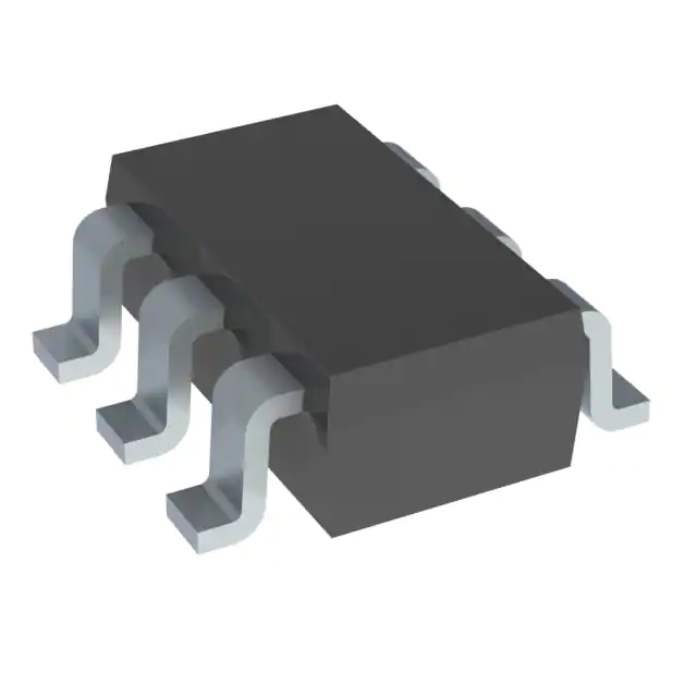
- Part No.:
- MP6650GJL-0000-Z
- Manufacturer:
- Monolithic Power Systems Inc.
- Category:
- Motor Drivers, Controllers
- Package:
- SOT-23-6 Thin, TSOT-23-6
- Datasheet:
-
 MP6650GJL-0000-Z.pdf
- Description:
- 18V, 2A,SINGLE-PHASE, BLDC MOTOR
- Quantity:
- Payment:

- Shipping:

Inventory:4,940
Please send an inquiry. Send us your inquiry, and we will respond immediately.
Product details
Overview
MP6650GJL-0000-Z from Monolithic Power Systems is a single-phase brushless DC motor driver IC with integrated Hall-effect sensor, power MOSFETs (740 mΩ total RDS(on)), and reverse-voltage protection. It delivers up to 2 A output current, operates from 3.3 V to 18 V, and features configurable speed curve, soft on/off phase transitions, and rotor lock detection via open-drain FG/RD pin. Used in CPU fan control for servers and desktops.
For engineers reviewing the MP6650GJL-0000-Z datasheet, MP6650GJL-0000-Z pinout, MP6650GJL-0000-Z application, or MP6650GJL-0000-Z equivalent, key selection criteria include integrated Hall sensing, 26 kHz fixed switching frequency, 2 kHz–100 kHz PWM input compatibility, thermal/overvoltage/rotor-lock protections, and TSOT23-6-L package footprint constraints.
Technical Context
The MP6650 implements closed-loop commutation using an embedded Hall sensor to detect rotor position and synchronize H-bridge switching with winding BEMF zero-crossing via automatic phase-lock logic. Its internal register-mapped configuration enables programmable start-up duty (0x14H), current limit (SUCL bits), and soft-switching enable (SOFTEN bit).
It integrates dual N-channel MOSFETs forming a half-bridge (OUT1/OUT2), supports PWM-based speed control with linear duty mapping, and provides dual-function FG/RD pin - configurable as tachometer output (1× or ½× Hall frequency) or open-drain rotor deadlock fault indicator with adaptive retry timing (0.6 s detection + 1.8–3.6 s lock-retry).
Key Specifications
| Parameter | Value and Actual Design Meaning |
|---|---|
| Input Voltage Range | 3.3 V to 18 V - supports wide-range 12 V fan rails and legacy 5 V or 3.3 V systems without external LDO. |
| Output Current Capability | Up to 2 A - sufficient for high-airflow CPU fans up to ~30 W mechanical load at 12 V. |
| Switching Frequency | Fixed 26 kHz - above audible range to eliminate fan coil whine and simplify EMI filtering. |
| PWM Input Frequency Range | 2 kHz to 100 kHz - compatible with standard motherboard PWM controllers and microcontroller GPIO outputs. |
| Hall Sensor Sensitivity | Operate point ±1–2 mT, hysteresis 2–4 mT - reliably detects small-gap rotor magnets in compact fan assemblies. |
| Thermal Shutdown Threshold | 150 °C with 25 °C hysteresis - enables automatic recovery after transient overload without system reset. |
| Reverse Voltage Protection | Active down to −18 V - eliminates need for external series diode in supply line, reducing BOM count and forward drop loss. |
Pinout & Package
MP6650GJL-0000-Z is housed in a TSOT23-6-L package - a 6-pin, lead-free, RoHS-compliant surface-mount package with 0.95 mm pitch, 2.9 mm × 1.6 mm footprint, and exposed pad for thermal enhancement. Pin 1 is lower-left when reading top marking left-to-right.
| Pin/Terminal | Circuit Role | Design Meaning |
|---|---|---|
| 1 GND | Power ground reference | Common return path for motor current, Hall sensor, and internal LDO; must be low-impedance connection to PCB ground plane. |
| 2 VCC | Supply input | Accepts 3.3–18 V DC; includes reverse-voltage protection and UVLO (3.25 V rising threshold) to prevent latch-up during brownout. |
| 3 FG/RD | Open-drain bidirectional signal | Configurable as tachometer (FG) or rotor lock fault (RD); requires external pull-up; outputs pulse train proportional to motor RPM or active-low fault flag. |
| 4 PWM | Speed control input | Accepts 2–100 kHz PWM; internal 41–50 kΩ pull-up enables direct MCU GPIO drive without external resistor; controls output duty cycle linearly. |
| 5 OUT2 | Motor phase output 2 | Midpoint of internal N-channel half-bridge; connects directly to one terminal of single-phase BLDC motor winding. |
| 6 OUT1 | Motor phase output 1 | Midpoint of same half-bridge; complementary to OUT2; together they drive unidirectional current through motor coil during commutation. |
Key Features
| Feature | Design Value |
|---|---|
| Integrated Hall sensor with ±1–2 mT operate point | Enables self-contained rotor position sensing without external sensor placement or alignment, reducing mechanical assembly complexity. |
| Soft on/off phase transition (22.5°–45° angle) | Reduces torque ripple and acoustic noise by ramping PWM duty in ≤16 steps, minimizing abrupt current changes that cause vibration. |
| Configurable current limit (0.7 A / 1.1 A / 1.6 A / 2 A) | Allows tuning motor acceleration and stall current per fan model via OTP register SUCL[1:0], preventing overcurrent damage during startup. |
| Automatic phase-lock detection | Synchronizes switching edges to winding BEMF zero-crossing using Hall signal timing, ensuring optimal torque generation across speed range. |
| Programmable start-up duty (0x14H register) | Defines minimum PWM input duty (e.g., 12.5%) required to initiate rotation, eliminating false starts under low-duty idle conditions. |
Applications
| CPU Fan Control | Server Chassis Cooling |
|---|---|
|
Use Scenario: Regulating rotational speed of 40–120 mm axial fans mounted on CPU heatsinks in desktop PCs and workstations. IC Role / Device Role / Timing Role: Single-phase BLDC driver with integrated Hall sensor providing closed-loop commutation, PWM-based speed modulation, and FG tach feedback to host controller. Use Value: Eliminates need for external Hall sensor and discrete MOSFETs, reducing board area by >40% versus discrete solutions while maintaining <±3% speed regulation accuracy. |
Use Scenario: Managing airflow in 1U–4U rack-mounted servers where thermal headroom is constrained and fan reliability is critical. IC Role / Device Role / Timing Role: Motor driver with rotor lock detection (RD) and automatic retry (3.6 s default), enabling autonomous recovery from dust-clogged or stalled fans without BMC intervention. Use Value: Reduces unplanned downtime by detecting and recovering from rotor deadlock within 4.2 s, avoiding full-system thermal shutdown. |
| Industrial Embedded Fan Modules | Network Equipment Thermal Management |
|
Use Scenario: Driving brushless fans in sealed industrial HMIs, PLC enclosures, or edge AI gateways operating at −40°C to +125°C ambient. IC Role / Device Role / Timing Role: High-integration motor controller with −40°C to +125°C junction-rated operation, UVLO/OVP/thermal shutdown, and reverse-voltage protection for harsh environments. Use Value: Ensures continuous cooling under voltage transients (e.g., 25 V surge) and polarity reversal events common in field-deployed equipment. |
Use Scenario: Controlling fans in 5G baseband units, optical line terminals, or enterprise switches where EMI-sensitive RF sections coexist with high-power digital ASICs. IC Role / Device Role / Timing Role: Fixed 26 kHz switching driver minimizing conducted noise in 15–25 kHz band, with soft-switching to suppress high-frequency harmonics. Use Value: Meets CISPR 32 Class B radiated emissions limits without additional ferrite beads or shielding, simplifying EMC validation. |
Equivalent & Alternatives
The following parts are listed as comparable options for similar single-phase BLDC motor driver applications.
| Alternative Part | Technical Difference | Application Difference | Selection Advice |
|---|---|---|---|
| MP6651GJL-Z | Same pinout and register map; adds I²C interface for real-time parameter readback and dynamic tuning (e.g., live current limit adjustment). | Required where host MCU needs runtime diagnostics (e.g., fan health monitoring, predictive maintenance). | Select MP6651GJL-Z if firmware-level visibility into motor current, temperature, or Hall status is needed; otherwise MP6650GJL-0000-Z offers lower cost and simpler integration. |
| TB67H401FNG | Discrete gate driver + external Hall sensor; no integrated MOSFETs or reverse-voltage protection; requires 6–20 V external FETs and bias circuitry. | Suitable for higher-current (>3 A) or custom-winding motors where thermal design demands separate power stage layout. | Choose TB67H401FNG only when >2 A peak current, multi-phase topology, or specialized motor winding configurations are required - not a drop-in replacement. |
Compared with MP6651GJL-Z, MP6650GJL-0000-Z trades diagnostic flexibility for lower BOM cost and reduced layout complexity; compared with TB67H401FNG, it delivers full integration but limits max current to 2 A and fixes switching frequency at 26 kHz.
Availability
MP6650GJL-0000-Z is available at Aetrix Electronics and suitable for CPU fan control, server chassis cooling, industrial embedded fan modules, and network equipment thermal management requiring stable component supply and long-term lifecycle support.
Supply support for MP6650GJL-0000-Z includes scheduled delivery planning, volume procurement assistance, BOM continuity management, traceable sourcing, and lifecycle availability coordination for OEM customers, industrial embedded developers, connected-device designers, and electronics production programs.
Manufacturer
Monolithic Power Systems (MPS) is a fabless semiconductor company specializing in high-performance power management ICs, including DC/DC converters, motor drivers, and LED drivers, with global manufacturing and quality certifications.
The MP6650 belongs to MPS's Phase Fan Driver product line, designed specifically for cost-sensitive, space-constrained BLDC fan applications requiring integrated Hall sensing, robust protection, and minimal external components.
FAQ
What is the function of the FG/RD pin?
The FG/RD pin is a multifunction open-drain output. When configured via register 0x0A[1:0] = 00 or 01, it outputs a pulse train (1× or ½× Hall frequency) indicating motor RPM. When set to 11, it asserts low during rotor lock detection. External pull-up is mandatory; typical value is 4.7 kΩ to 5 V.
Does MP6650GJL-0000-Z require external MOSFETs?
No. The device integrates two N-channel power MOSFETs (HS-FET and LS-FET) forming a half-bridge with total RDS(on) of 740 mΩ (480 mΩ HS + 260 mΩ LS at 25°C). These directly drive the motor winding between OUT1 and OUT2; no external switches are needed.
How is rotor lock detection time configured?
Rotor lock detection time is fixed at 0.6 s (tRD), but the lock-retry interval is configurable via register 0x0F[5:4]. Settings 00–11 select 1.8 s, 2.4 s, 3.0 s, or 3.6 s retry delays respectively. Default is 11 → 3.6 s, allowing full recovery before re-attempting startup.
Can the output switching frequency be adjusted?
No. The MP6650 uses a fixed 26 kHz internal oscillator for H-bridge switching. This frequency is optimized to avoid audible noise and simplify EMI filter design. PWM input frequency (2–100 kHz) only controls output duty cycle, not switching frequency.
What package variant does MP6650GJL-0000-Z use?
MP6650GJL-0000-Z uses the TSOT23-6-L package: 6-pin, 2.9 mm × 1.6 mm body, 0.95 mm pitch, with pin 1 in the lower-left corner when viewing top marking left-to-right. "L" denotes normal pinout orientation (GND–VCC–FG/RD–PWM–OUT2–OUT1).
Is reverse-voltage protection active during operation?
Yes. Input reverse-voltage protection (RVP) functions continuously across the full operating range. When VCC is reversed (e.g., −18 V), internal circuitry blocks conduction and limits reverse current to ≤1 mA, protecting both the IC and upstream power source without external diodes.
How is the soft-start time selected?
Soft-start time for PWM duty transitions is set by register 0x0A[2] (TSS bit): 0 = 2.6 s, 1 = 5.2 s (default). This parameter governs the ramp rate when changing fan speed to limit inrush current and reduce mechanical stress on bearings and blades.
MP6650GJL-0000-Z Specifications
- Product attributes
- Attribute value
- Manufacturer:
- Monolithic Power Systems Inc.
- Series:
- -
- Package/Case:
- SOT-23-6 Thin, TSOT-23-6
- Packaging:
- Tape & Reel (TR)
- Product Status:
- Active
- Motor Type - Stepper:
- Unipolar
- Motor Type - AC, DC:
- Brushless DC (BLDC)
- Function:
- Driver
- Output Configuration:
- Half Bridge (2)
- Interface:
- PWM
- Technology:
- Power MOSFET
- Step Resolution:
- -
- Applications:
- Brushless DC (BLDC)
- Current - Output:
- 2A
- Voltage - Supply:
- 3.3V ~ 18V
- Voltage - Load:
- -
- Operating Temperature:
- -40°C ~ 125°C (TJ)
- Grade:
- -
- Qualification:
- -
- Mounting Type:
- Surface Mount
- Supplier Device Package:
- TSOT-23-6-L
MP6650GJL-0000-Z FAQ
1.How can I place an order for MP6650GJL-0000-Z through Aetrix?
Please submit a Request for Quotation (RFQ) for MP6650GJL-0000-Z on Aetrix. Our sales agent will provide a competitive quotation and guide you through the order confirmation once you accept the terms.
2.Are the price and stock information for MP6650GJL-0000-Z reliable?
The price and inventory of MP6650GJL-0000-Z are updated periodically and may fluctuate due to market conditions. Stock and pricing data are typically refreshed every 24 hours. Quotation validity for MP6650GJL-0000-Z is usually 5 days.
3.What payment methods are accepted for MP6650GJL-0000-Z?
We accept Wire Transfer, PayPal, Credit Card, Western Union, MoneyGram, and Escrow for MP6650GJL-0000-Z transactions.
Note: Certain payment methods may incur a processing fee.
4.How is shipping managed for MP6650GJL-0000-Z?
MP6650GJL-0000-Z orders can be shipped via leading logistics carriers, including DHL, UPS, FedEx, TNT, or Registered Mail.
Once your MP6650GJL-0000-Z order is processed, you will receive an email with the shipment details and tracking number.
Note: Tracking information may take up to 24 hours to appear. Express delivery typically takes 3–5 business days.
5.How can I obtain technical support or documentation for MP6650GJL-0000-Z?
For technical support, including MP6650GJL-0000-Z datasheets, pinout diagrams, or application guidance, please contact our engineering support team. They can provide detailed documentation and assistance for your MP6650GJL-0000-Z requirements.
6.How does Aetrix verify that MP6650GJL-0000-Z is sourced from the original manufacturer or authorized distributors?
All MP6650GJL-0000-Z products on Aetrix are procured from qualified distributors and authorized channels. Our dedicated quality assurance team conducts strict verification, including traceability checks and, if necessary, third-party testing. This ensures that MP6650GJL-0000-Z meets industry standards.
7.What is the process for return or replacement of MP6650GJL-0000-Z?
All MP6650GJL-0000-Z units undergo pre-shipment inspection (PSI). If there is an issue with MP6650GJL-0000-Z, returns or replacements are accepted under the following conditions:
1.Quantity discrepancies, incorrect items, or visible external defects (such as breakage or corrosion), acknowledged by Aetrix.
2.The issue is reported within 90 days of delivery.
3.The MP6650GJL-0000-Z part is unused and in its original packaging.
Return procedure for MP6650GJL-0000-Z:
1.Submit a request within 90 days.
2.Obtain a Return Material Authorization (RMA) from Aetrix.
MP6650GJL-0000-Z Tags

-
DRV2603RUNR
Texas Instruments

-
DRV8837CDSGR
Texas Instruments

-
DRV8837DSGR
Texas Instruments
-
DRV8838DSGR
Texas Instruments

-
DRV8839DSSR
Texas Instruments

-
EMC2301-1-ACZL-TR
Microchip Technology
-
DRV8231ADSGR
Texas Instruments

-
EMC2302-2-AIZL-TR
Microchip Technology

-
DRV8800PWPR
Texas Instruments
-
DRV8835DSSR
Texas Instruments

-
EMC2303-1-KP-TR
Microchip Technology

-
DRV8876PWPR
Texas Instruments
Tech Hub

A practical engineering guide to 3.3V and 5V logic compatibility, input thresholds, resistor dividers, translator ICs, MOSFET level shifting, I2C pull-ups, timing limits and power-sequencing risks.

The 74HC595 uses push-pull logic outputs, while the TPIC6B595 uses 50 V open-drain DMOS sinks for higher-power loads. This guide compares timing, current limits, 3.3 V interfacing, load wiring, thermal…

The 74HC595 converts serial data into eight stable parallel outputs. This guide covers pin functions, shift and storage timing, OE and MR behavior, drive-current limits, cascading, voltage compatibilit…

A technical comparison of level-sensitive latches and edge-triggered flip-flops, covering timing windows, setup and hold limits, master–slave operation, time borrowing, race-through, HDL inference and…

A D latch stores one bit while Enable controls when data can pass. This reference covers gate-level operation, truth tables, transparency, setup and hold timing, LE versus OE, common ICs and practical …

An SR latch stores one bit through cross-coupled feedback. This engineering reference covers NOR and NAND implementations, truth tables, forbidden-state recovery, gated operation, switch debouncing, fa…

Latch circuits retain one bit through feedback. This technical reference covers SR and D latches, truth tables, transparency, timing limits, latch-versus-flip-flop behavior, applications and common log…

An engineering guide to LED driver operation, constant-current and constant-voltage outputs, linear and switching topologies, dimming, IC selection, calculations, replacement compatibility, and fault c…

Operational amplifier guide covering op amp basics, feedback, ideal vs real op amps, common configurations, buffer circuits, offset, bias current, gain-bandwidth, slew rate, rail-to-rail limits and sel…

Jumper cables guide covering safe connection order, red and black clamp placement, final ground connection, cable gauge, length, clamp quality, copper vs CCA cables, jump starter comparison and battery…


