
 My Inquiry
 My Account


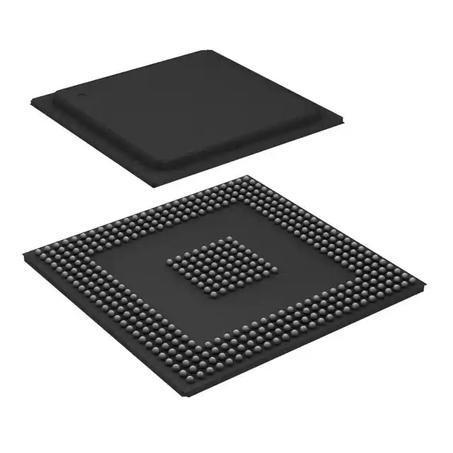
NXP Semiconductors MPC5554MZP132
- Part No.:
- MPC5554MZP132
- Manufacturer:
- NXP Semiconductors
- Category:
- Microcontrollers
- Package:
- 416-BBGA
- Datasheet:
-
 MPC5554MZP132.pdf
- Description:
- IC MCU 32BIT 2MB FLASH 416PBGA
- Quantity:
- Payment:

- Shipping:

Inventory:145
Please send an inquiry. Send us your inquiry, and we will respond immediately.
Product details
Overview
MPC5554MZP132 from NXP Semiconductors (formerly Freescale) is a 32-bit Power Architecture® embedded MCU designed for automotive powertrain and chassis control. It features a 132 MHz e200z6 core, 2 MB on-chip flash, 64 KB SRAM, dual eTPU engines (64 hardware channels), and integrated FlexCAN, DSPI, eSCI, and eQADC subsystems - deployed in engine control units (ECUs) requiring ASIL-B functional safety compliance.
For engineers reviewing the MPC5554MZP132 datasheet, MPC5554MZP132 pinout, MPC5554MZP132 application, or MPC5554MZP132 equivalent, key selection criteria include its 416-pin PBGA SnPb package, –40°C to +125°C operating range, dual eTPU timing precision for ignition/fuel injection, and integrated voltage regulator controller (VRC) supporting external pass transistor control.
Technical Context
The MPC5554MZP132 implements the Power Architecture e200z6 core with full user-mode compatibility to PowerPC, including floating-point library support and DSP-enhanced instructions. Its memory hierarchy includes 32 KB unified cache, 64 KB on-chip SRAM, and 2 MB internal flash with H7Fa architecture enabling single-cycle read access and background erase capability.
Real-time I/O control is handled by two independent enhanced Time Processor Units (eTPU), each managing 32 hardware channels with 24-bit resolution, angle-clock synchronization, and double-action channel support - complemented by a 24-channel eMIOS for PWM generation (edge- and center-aligned) and modular timer functions.
Key Specifications
| Parameter | Value and Actual Design Meaning |
|---|---|
| Core Architecture | e200z6 Power Architecture CPU, 100% PowerPC user-mode compatible with DSP extensions |
| Max Operating Frequency | 132 MHz nominal (128 MHz system clock + 2% FM modulation) |
| Flash Memory | 2 MB H7Fa flash with background erase, single-cycle read, and ECC protection |
| SRAM | 64 KB on-chip SRAM, accessible at full core speed without wait states |
| eTPU Channels | 64 total hardware channels across two independent eTPU engines for deterministic timing |
| FlexCAN Interfaces | Two CAN 2.0B-compliant controllers with message RAM and loopback self-test mode |
| Operating Temperature | –40°C to +125°C ambient, qualified for automotive under AEC-Q100 Grade 1 |
| Package | 416-ball PBGA, SnPb (lead-based) solder finish, 27 mm × 27 mm footprint |
Pinout & Package
The MPC5554MZP132 is housed in a 416-ball plastic ball grid array (PBGA) package with SnPb solder balls, optimized for automotive PCB thermal and mechanical reliability. Pin assignments follow the standardized MPC5553/54/56/66/67 416-PBGA layout per Freescale Document Number MPC5554 Rev. 4, Section 4.1.
| Pin/Terminal | Circuit Role | Design Meaning |
|---|---|---|
| VDD | 1.5 V Core Supply | Primary power rail for CPU, cache, and internal logic; requires tight regulation ±10% (1.35–1.65 V) |
| VDD33 | 3.3 V I/O Supply | Power for GPIO, FlexCAN, DSPI, and eSCI interfaces; supports 3.3 V LVTTL signaling |
| VDDA | Analog Supply (5 V) | Provides clean 5 V bias for eQADC reference and analog input circuitry; isolated from digital supplies |
| RESET | Active-Low Reset Input | Asynchronous reset signal; asserted during power-up until all supply rails meet POR thresholds |
| CLKIN | External Clock Input | Accepts 4–40 MHz crystal or oscillator input for FMPLL clock synthesis |
| FMPLLOUT | Fractional PLL Output | Drives core/system clocks; enables dynamic frequency scaling and jitter-controlled timing |
| eTPU_A[0:31] | eTPU Engine A Channel Signals | Dedicated pins for high-resolution timing capture/generation (e.g., crank/cam sensing, spark timing) |
| CAN0_TX / CAN0_RX | FlexCAN 0 Differential Interface | Direct connection to CAN transceiver; supports 1 Mbps baud rate with built-in filtering |
Key Features
| Feature | Design Value |
|---|---|
| Enhanced Time Processor Unit (eTPU) | Two independent engines delivering deterministic 24-bit timing with <100 ns resolution for ignition/fuel events |
| On-Chip Voltage Regulator Controller (VRC) | Drives external NPN pass transistor to regulate 1.5 V core supply; eliminates need for discrete LDO in ECU designs |
| H7Fa Flash Memory | 2 MB embedded flash with background erase, ECC, and fast read enabling safe OTA updates without runtime interruption |
| Functional Safety Support | Built-in lockstep monitor, memory BIST, and error-correcting code for flash/SRAM - meets ISO 26262 ASIL-B requirements |
| Flexible Serial Peripherals | Dual FlexCAN, triple DSPI, dual eSCI, and 40-channel eQADC enable consolidated sensor/actuator communication in compact ECUs |
| System Integration Unit (SIU) | Centralized pad configuration, GPIO control, interrupt routing, and eQADC trigger multiplexing - reduces software initialization overhead |
Applications
| Gasoline Engine Control Unit (ECU) | Diesel Engine Control Unit (ECU) |
|---|---|
|
Use Scenario: Real-time management of fuel injection timing, spark advance, throttle position, and knock detection in inline-4 gasoline engines. IC Role / Device Role / Timing Role: Primary controller executing closed-loop combustion algorithms; eTPU synchronizes spark/fuel events to crankshaft angle with sub-degree precision. Use Value: Enables precise stoichiometric air-fuel ratio control and adaptive learning - reducing emissions and improving fuel economy within Euro 6/LEV III limits. |
Use Scenario: High-pressure common-rail diesel injection control with variable geometry turbocharger actuation and exhaust gas recirculation (EGR) management. IC Role / Device Role / Timing Role: Master timing controller coordinating up to 5 injection events per cycle via eTPU-driven solenoid drivers and PWM-controlled vanes. Use Value: Supports multi-pulse injection strategies and transient torque response within 10 ms - meeting Tier 4 Final NOx/PM targets. |
| Electric Power Steering (EPS) Control | Brake-by-Wire Actuation Module |
|
Use Scenario: Torque assist calculation, motor current control, and fault-tolerant steering angle feedback in column-assist EPS systems. IC Role / Device Role / Timing Role: Safety-critical controller running ASIL-C decomposition; eMIOS generates center-aligned PWM for 3-phase inverter drive. Use Value: Delivers <50 µs current-loop response time and redundant sensor fusion - satisfying ISO 26262 ASIL-B hardware metrics. |
Use Scenario: Redundant hydraulic pressure modulation and wheel-speed-based brake force distribution in electromechanical brake (EMB) modules. IC Role / Device Role / Timing Role: Dual-core lockstep-capable MCU monitoring pedal position, vehicle dynamics, and actuator status via FlexCAN and eQADC. Use Value: Achieves <100 ms end-to-end latency from pedal input to caliper actuation - enabling fail-operational braking per ISO 26262 Annex D. |
Equivalent & Alternatives
The following parts are listed as comparable options for similar automotive microcontroller applications.
| Alternative Part | Technical Difference | Application Difference | Selection Advice |
|---|---|---|---|
| S32K144HAT0MLHT | ARM Cortex-M4F core @ 112 MHz; 1 MB flash; no eTPU; includes HSE security engine | Targeted at body electronics and gateway modules; lacks deterministic timing for powertrain | Prefer when cryptographic services, AUTOSAR OS support, or lower power consumption are prioritized over ultra-precise timing |
| MPC5604B | Same e200z0 core family but 64 MHz max; 512 KB flash; single eTPU (32 channels); no VRC | Legacy powertrain designs with less demanding real-time requirements and simpler ECU architectures | Select only for cost-sensitive brownfield upgrades where 132 MHz performance and dual eTPU are unnecessary |
Compared with S32K144HAT0MLHT and MPC5604B, the MPC5554MZP132 uniquely delivers deterministic 24-bit timing via dual eTPU engines and integrated VRC control - making it irreplaceable for ASIL-B-compliant gasoline/diesel ECU designs requiring sub-microsecond event synchronization and external 1.5 V regulation.
Availability
MPC5554MZP132 is available at Aetrix Electronics and suitable for automotive powertrain control, electric power steering, brake-by-wire systems, and industrial motion control requiring stable component supply across extended temperature ranges and long production lifecycles.
Supply support for MPC5554MZP132 includes scheduled delivery planning, volume procurement assistance, BOM continuity management, traceable sourcing, and lifecycle availability coordination for OEM customers, industrial embedded developers, connected-device designers, and electronics production programs.
Manufacturer
NXP Semiconductors is a global semiconductor leader specializing in secure connectivity solutions for automotive, industrial, and IoT applications, with deep heritage in Power Architecture technology.
The MPC5554MZP132 belongs to the MPC5500 family - engineered specifically for high-reliability automotive powertrain and chassis control, emphasizing deterministic real-time performance, functional safety, and integration of timing-critical peripherals.
FAQ
What is the maximum junction temperature specification for the MPC5554MZP132?
The MPC5554MZP132 has a maximum junction temperature (TJ) of 150°C, validated per JEDEC JESD51 standards. This rating enables operation in under-hood environments where ambient temperatures reach 125°C, provided thermal design meets RθJA ≤ 18°C/W on a four-layer board. The device includes on-die thermal sensors monitored via SIU registers to trigger safe shutdown if TJ exceeds threshold.
Does the MPC5554MZP132 support ISO 26262 functional safety certification?
Yes, the MPC5554MZP132 includes hardware-level safety mechanisms required for ISO 26262 ASIL-B compliance: lockstep-capable e200z6 core (with optional checker core), ECC on flash/SRAM, memory BIST, and VRC fault detection. Freescale's Functional Safety Manual (Document AN4369) provides diagnostic coverage analysis and FMEDA data specific to MPC5554MZP132.
What is the role of the Voltage Regulator Controller (VRC) in the MPC5554MZP132?
The VRC in the MPC5554MZP132 drives an external NPN pass transistor to regulate the 1.5 V core supply (VDD) from a higher 3.3 V or 5 V source. It eliminates the need for a discrete LDO, reduces BOM count, and enables precise control of VDD ramp rates during power-up/down - critical for avoiding POR reassertion in automotive ECUs.
How many CAN interfaces does the MPC5554MZP132 integrate, and what protocol versions do they support?
The MPC5554MZP132 integrates two FlexCAN controllers compliant with ISO 11898-1:2015 (CAN 2.0B), supporting both standard (11-bit) and extended (29-bit) identifiers, bit rates up to 1 Mbps, and hardware message filtering. Each controller includes 64-message RAM buffers and supports loopback self-test mode for diagnostic validation.
Is the MPC5554MZP132 pin-compatible with other members of the MPC5500 family?
No - the MPC5554MZP132 uses the 416-ball PBGA package shared with MPC5553/5554/5556/5566/5567, but pin functions differ significantly across variants due to differing peripheral sets (e.g., MPC5553 lacks second eTPU). Direct replacement requires full schematic and layout review; migration paths must follow NXP's MPC5500 Family Migration Guide (AN4277).
MPC5554MZP132 Specifications
- Product attributes
- Attribute value
- Manufacturer:
- NXP Semiconductors
- Package/Case:
- 416-BBGA
- Series:
- MPC55xx Qorivva
- Packaging:
- Tray
- Product Status:
- Not For New Designs
- Programmable:
- Not Verified
- Core Processor:
- e200z6
- Core Size:
- 32-Bit Single-Core
- Speed:
- 132MHz
- Connectivity:
- CANbus, EBI/EMI, SCI, SPI
- Peripherals:
- DMA, POR, PWM, WDT
- Number of I/O:
- 256
- Program Memory Size:
- 2MB (2M x 8)
- Program Memory Type:
- FLASH
- EEPROM Size:
- -
- RAM Size:
- 64K x 8
- Voltage - Supply (Vcc/Vdd):
- 1.35V ~ 1.65V
- Data Converters:
- A/D 40x12b
- Oscillator Type:
- External
- Operating Temperature:
- -40°C ~ 125°C (TA)
- Grade:
- -
- Qualification:
- -
- Mounting Type:
- Surface Mount
- Supplier Device Package:
MPC5554MZP132 FAQ
1.How can I place an order for MPC5554MZP132 through Aetrix?
Please submit a Request for Quotation (RFQ) for MPC5554MZP132 on Aetrix. Our sales agent will provide a competitive quotation and guide you through the order confirmation once you accept the terms.
2.Are the price and stock information for MPC5554MZP132 reliable?
The price and inventory of MPC5554MZP132 are updated periodically and may fluctuate due to market conditions. Stock and pricing data are typically refreshed every 24 hours. Quotation validity for MPC5554MZP132 is usually 5 days.
3.What payment methods are accepted for MPC5554MZP132?
We accept Wire Transfer, PayPal, Credit Card, Western Union, MoneyGram, and Escrow for MPC5554MZP132 transactions.
Note: Certain payment methods may incur a processing fee.
4.How is shipping managed for MPC5554MZP132?
MPC5554MZP132 orders can be shipped via leading logistics carriers, including DHL, UPS, FedEx, TNT, or Registered Mail.
Once your MPC5554MZP132 order is processed, you will receive an email with the shipment details and tracking number.
Note: Tracking information may take up to 24 hours to appear. Express delivery typically takes 3–5 business days.
5.How can I obtain technical support or documentation for MPC5554MZP132?
For technical support, including MPC5554MZP132 datasheets, pinout diagrams, or application guidance, please contact our engineering support team. They can provide detailed documentation and assistance for your MPC5554MZP132 requirements.
6.How does Aetrix verify that MPC5554MZP132 is sourced from the original manufacturer or authorized distributors?
All MPC5554MZP132 products on Aetrix are procured from qualified distributors and authorized channels. Our dedicated quality assurance team conducts strict verification, including traceability checks and, if necessary, third-party testing. This ensures that MPC5554MZP132 meets industry standards.
7.What is the process for return or replacement of MPC5554MZP132?
All MPC5554MZP132 units undergo pre-shipment inspection (PSI). If there is an issue with MPC5554MZP132, returns or replacements are accepted under the following conditions:
1.Quantity discrepancies, incorrect items, or visible external defects (such as breakage or corrosion), acknowledged by Aetrix.
2.The issue is reported within 90 days of delivery.
3.The MPC5554MZP132 part is unused and in its original packaging.
Return procedure for MPC5554MZP132:
1.Submit a request within 90 days.
2.Obtain a Return Material Authorization (RMA) from Aetrix.
MPC5554MZP132 Tags

-
ATTINY4-TSHR
Microchip Technology
-
ATTINY10-TSHR
Microchip Technology
-
ATTINY10-TS8R
Microchip Technology

-
ATTINY202-SSNR
Microchip Technology
-
ATTINY202-SSFR
Microchip Technology
-
ATTINY402-SSNR
Microchip Technology

-
PIC16F15213T-I/MF
Microchip Technology
-
PIC16F15213-E/MF
Microchip Technology

-
PIC10F200T-I/OT
Microchip Technology
-
ATTINY412-SSNR
Microchip Technology
-
PIC10F202T-I/OT
Microchip Technology

-
ATTINY404-SSNR
Microchip Technology
Tech Hub

A practical engineering guide to 3.3V and 5V logic compatibility, input thresholds, resistor dividers, translator ICs, MOSFET level shifting, I2C pull-ups, timing limits and power-sequencing risks.

The 74HC595 uses push-pull logic outputs, while the TPIC6B595 uses 50 V open-drain DMOS sinks for higher-power loads. This guide compares timing, current limits, 3.3 V interfacing, load wiring, thermal…

The 74HC595 converts serial data into eight stable parallel outputs. This guide covers pin functions, shift and storage timing, OE and MR behavior, drive-current limits, cascading, voltage compatibilit…

A technical comparison of level-sensitive latches and edge-triggered flip-flops, covering timing windows, setup and hold limits, master–slave operation, time borrowing, race-through, HDL inference and…

A D latch stores one bit while Enable controls when data can pass. This reference covers gate-level operation, truth tables, transparency, setup and hold timing, LE versus OE, common ICs and practical …

An SR latch stores one bit through cross-coupled feedback. This engineering reference covers NOR and NAND implementations, truth tables, forbidden-state recovery, gated operation, switch debouncing, fa…

Latch circuits retain one bit through feedback. This technical reference covers SR and D latches, truth tables, transparency, timing limits, latch-versus-flip-flop behavior, applications and common log…

An engineering guide to LED driver operation, constant-current and constant-voltage outputs, linear and switching topologies, dimming, IC selection, calculations, replacement compatibility, and fault c…

Operational amplifier guide covering op amp basics, feedback, ideal vs real op amps, common configurations, buffer circuits, offset, bias current, gain-bandwidth, slew rate, rail-to-rail limits and sel…

Jumper cables guide covering safe connection order, red and black clamp placement, final ground connection, cable gauge, length, clamp quality, copper vs CCA cables, jump starter comparison and battery…


