
 My Inquiry
 My Account


NXP Semiconductors MPC7410VS500LE
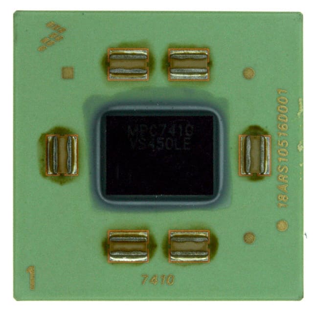
- Part No.:
- MPC7410VS500LE
- Manufacturer:
- NXP Semiconductors
- Category:
- Microprocessors
- Package:
- 360-CLGA, FCCLGA
- Datasheet:
-
 MPC7410VS500LE.pdf
- Description:
- IC MPU MPC74XX 500MHZ 360FCCLGA
- Quantity:
- Payment:

- Shipping:

Inventory:3,537
Please send an inquiry. Send us your inquiry, and we will respond immediately.
Product details
Overview
MPC7410VS500LE from Freescale Semiconductor is a 500 MHz PowerPC G4 RISC microprocessor implementing the full 32-bit PowerPC architecture with AltiVec™ SIMD engine, 32 KB L1 instruction and data caches, integrated L2 cache controller, and MPX bus interface. It operates at 1.8 V core voltage, supports 32-bit address/64-bit data system bus, and targets high-performance embedded computing, digital signal processing, and network infrastructure applications.
For engineers reviewing the MPC7410VS500LE datasheet, MPC7410VS500LE pinout, MPC7410VS500LE application, or MPC7410VS500LE equivalent, key selection criteria include confirmed 500 MHz core frequency, AltiVec-enabled vector processing capability, L2 cache interface configurability (1–2 MB, 32/64/128-byte line), 360-ball CBGA package thermal resistance (RθJMA = 18°C/W), and support for doze/nap/sleep power management modes.
Technical Context
The MPC7410VS500LE implements a five-stage scalar pipeline (fetch, decode/dispatch, execute, complete/writeback) with out-of-order execution, eight-entry completion queue, and dual-issue dispatch to eight independent execution units-including FXU1/FXU2, FP unit, AltiVec permute/ALU, and branch unit. Its AltiVec unit features full 128-bit datapaths, dedicated 32-entry vector register file, and hardware-pipelined VSIU/VCIU/VFPU subunits.
It integrates a 32 KB iL1 and 32 KB dL1 cache (eight-way set-associative, 32-byte lines), nonblocking design with hits-under-misses, and an external L2 interface supporting 512 KB–2 MB two-way set-associative SRAM with configurable direct-mapped mode. The MPX bus extension provides mode-compatible 60x interface with 32-bit address/64-bit data width and bus-to-core multipliers up to 9×.
Key Specifications
| Parameter | Value and Actual Design Meaning |
|---|---|
| Core Frequency | 500 MHz - Guaranteed maximum operating frequency under specified thermal and voltage conditions (VDD = 1.8 V ± 100 mV, Tj ≤ 105°C). |
| L1 Cache | 32 KB instruction + 32 KB data - Eight-way set-associative, 32-byte lines, single-cycle access, pseudo-LRU replacement. |
| AltiVec Engine | Full 128-bit SIMD unit - Includes dedicated vector register file (32 × 128-bit), permute and ALU subunits, and hardware-pipelined integer/floating-point vector operations. |
| Bus Interface | MPX extension of 60x interface - 32-bit address / 64-bit data bus, selectable OVDD (1.8/2.5/3.3 V), bus-to-core multipliers up to 9×. |
| Power Modes | Doze/Nap/Sleep - Hardware-supported low-power states; Sleep mode draws ≤1.1 W (typical 600 mW) with PLL/DLL disabled. |
| Thermal Resistance | RθJMA = 18°C/W - Junction-to-ambient thermal resistance under natural convection on four-layer board (CBGA package). |
| Process Technology | 0.18 µm CMOS - Six-metal-layer fabrication enabling 10.5 million transistor density and 52 mm² die size. |
Pinout & Package
Package: 360-ball ceramic ball grid array (CBGA), surface-mount, 27 mm × 27 mm footprint, 1.27 mm ball pitch. Thermal performance optimized for industrial ambient (0–105°C junction temperature).
| Pin/Terminal | Circuit Role | Design Meaning |
|---|---|---|
| SYSCLK | Primary clock input | Accepts 33–133 MHz differential or single-ended clock; drives internal PLL to generate 500 MHz core frequency. |
| HRESET | Asynchronous reset input | Active-low global reset; samples BVSEL/L2VSEL at negation to configure I/O voltage thresholds. |
| BVSEL / L2VSEL | I/O voltage select control | Configures input threshold reference (1.8 V / 2.5 V / 3.3 V) for processor and L2 buses respectively. |
| VDD / AVDD / L2AVDD | Core and PLL supply pins | 1.8 V ± 100 mV DC; strict sequencing required-must not exceed OVDD/L2OVDD by >0.4 V during operation. |
| OVDD / L2OVDD | I/O supply pins | Separate 1.8 V / 2.5 V / 3.3 V supplies for processor and L2 buses; L2OVDD must be powered even if L2 interface unused. |
| TCK / TMS / TDI / TDO | JTAG boundary scan interface | IEEE 1149.1 compliant; enables factory test, debug, and in-system programming with defined DC limits per BVSEL state. |
Key Features
| Feature | Design Value |
|---|---|
| AltiVec SIMD Architecture | Enables parallel 128-bit integer/floating-point operations for real-time media encoding, radar signal processing, and AI inference acceleration. |
| Five-State Cache Coherency Protocol | Hardware-managed MESI+Intervention protocol supports full symmetric multiprocessing (SMP) without software coherency overhead. |
| Configurable L2 Cache Interface | Supports 1–2 MB external SRAM with selectable line sizes (32/64/128 bytes) and direct-mapped mode for deterministic latency-critical applications. |
| Out-of-Order Execution Engine | Eight-entry completion queue and dual-issue dispatch sustain peak throughput of two instructions per cycle despite pipeline stalls. |
| Thermal Management Support | Dedicated thermal monitoring circuitry and three-tier power gating (doze/nap/sleep) enable sustained operation in fanless embedded enclosures. |
Applications
| Telecom Baseband Processing | Industrial Motion Control |
|---|---|
Use Scenario: Real-time baseband modulation/demodulation and channel coding in 3G/4G wireless infrastructure equipment. IC Role / Device Role / Timing Role: Primary compute engine executing DSP algorithms via AltiVec-accelerated FFT, FIR, and Viterbi kernels. Use Value: 500 MHz core + 128-bit vector lanes deliver >1.2 GFLOPS peak performance while maintaining deterministic interrupt latency <500 ns. |
Use Scenario: Closed-loop servo control and multi-axis trajectory planning in CNC machines and robotics. IC Role / Device Role / Timing Role: Real-time deterministic controller managing PWM generation, encoder feedback, and safety monitoring. Use Value: Hardware cache coherency and SMP support enable dual-core lockstep or functional partitioning for SIL-3 compliance. |
| Avionics Display Systems | Network Packet Processing |
Use Scenario: High-resolution synthetic vision rendering and ARINC 661 widget composition in cockpit displays. IC Role / Device Role / Timing Role: Graphics and UI processor handling OpenGL ES rendering, video overlay, and touch response. Use Value: L1/L2 cache hierarchy and 128-bit memory bandwidth reduce frame buffer latency to <16 ms at 1080p60. |
Use Scenario: Deep packet inspection and policy enforcement in enterprise firewalls and SD-WAN edge routers. IC Role / Device Role / Timing Role: Flow classification and signature matching engine leveraging AltiVec for parallel pattern search. Use Value: Configurable L2 cache line size (128-byte) optimizes throughput for 64-byte packet metadata caching at 1+ Gbps line rate. |
Equivalent & Alternatives
The following parts are listed as comparable options for similar RISC microprocessor applications.
| Alternative Part | Technical Difference | Application Difference | Selection Advice |
|---|---|---|---|
| MPC7447A | 600 MHz core, 1 MB on-die L2 cache, same AltiVec and MPX interface; 90 nm process reduces power by 35% at same frequency. | Higher integration eliminates external L2 SRAM, simplifying PCB layout but increasing BOM cost and reducing configurability. | Select MPC7447A when L2 capacity and power efficiency outweigh flexibility in cache sizing and line configuration. |
| PPC440EP | 400 MHz core, no AltiVec, integrated DDR controller and PCI-X interface; designed for SoC-like embedded control rather than compute-intensive DSP. | Targeted at I/O-rich control plane applications (e.g., storage controllers), not signal processing or SMP workloads. | Select PPC440EP when system requires integrated peripherals over raw vector compute throughput and cache scalability. |
Compared with MPC7410VS500LE, MPC7447A offers higher clock speed and integrated L2 at lower power but sacrifices external L2 configurability, while PPC440EP trades AltiVec and cache scalability for integrated I/O and deterministic control-plane latency.
Availability
MPC7410VS500LE is available at Aetrix Electronics and suitable for telecom infrastructure, avionics display systems, and industrial motion control requiring stable component supply across extended product lifecycles.
Supply support for MPC7410VS500LE includes scheduled delivery planning, volume procurement assistance, BOM continuity management, traceable sourcing, and lifecycle availability coordination for OEM customers, industrial embedded developers, connected-device designers, and electronics production programs.
Manufacturer
Freescale Semiconductor (now part of NXP Semiconductors) is a fabless semiconductor company specializing in embedded processing, analog, and connectivity solutions for automotive, industrial, and networking markets.
The MPC7410VS500LE belongs to Freescale's PowerPC G4 family, engineered for high-throughput embedded computing where AltiVec-accelerated signal processing, SMP scalability, and thermal robustness are critical design requirements.
FAQ
What is the guaranteed maximum operating frequency of the MPC7410VS500LE?
The MPC7410VS500LE is binned and tested to guarantee stable operation at 500 MHz core frequency under specified conditions: VDD = 1.8 V ± 100 mV, junction temperature ≤105°C, and SYSCLK between 33–133 MHz. This rating is validated per Freescale's AC electrical specifications (Table 7) and reflects worst-case silicon at maximum thermal load. The MPC7410VS500LE achieves this via optimized PLL configuration and 0.18 µm process tuning.
Does the MPC7410VS500LE include on-die L2 cache?
No, the MPC7410VS500LE does not integrate L2 cache on-die. It features an external L2 cache interface supporting 512 KB–2 MB off-chip SRAM with configurable line sizes (32/64/128 bytes) and two-way set-associative or direct-mapped modes. The MPC7410VS500LE contains only L1 instruction and data caches (32 KB each) and an integrated L2 cache controller. External L2 implementation allows system designers to optimize capacity, latency, and cost per application.
What power management modes does the MPC7410VS500LE support?
The MPC7410VS500LE supports three hardware-controlled low-power states: Doze (core clocks gated, bus active), Nap (core and bus clocks gated, memory retained), and Sleep (all clocks stopped, PLL/DLL disabled). In Sleep mode, typical power drops to 600 mW; maximum is 1.1 W. These modes are entered via specific SPR writes and are essential for thermal management in fanless enclosures. The MPC7410VS500LE implements these without external logic, using on-chip power gating and voltage regulation controls.
How is I/O voltage configured on the MPC7410VS500LE?
I/O voltage thresholds for the processor bus (OVDD) and L2 bus (L2OVDD) are configured at reset by sampling BVSEL and L2VSEL pin states relative to HRESET. BVSEL = 0 selects 1.8 V, BVSEL = HRESET selects 2.5 V, and BVSEL = ¬HRESET selects 3.3 V. The MPC7410VS500LE requires corresponding OVDD/L2OVDD supply voltages to match selected thresholds-mismatch causes undefined behavior. Configuration is latched at HRESET negation and cannot be changed dynamically.
Is the MPC7410VS500LE pin-compatible with other MPC74xx devices?
The MPC7410VS500LE uses a 360-ball CBGA package identical to MPC7400/MPC7410 variants, but pin functions differ significantly due to AltiVec additions, L2 interface enhancements, and updated power domains. While mechanical footprint matches, signal mapping (e.g., new L2ASPARE pin, redefined cache control signals) and voltage domain assignments require PCB redesign. Therefore, the MPC7410VS500LE is not a drop-in replacement for earlier MPC74xx parts despite shared packaging.
MPC7410VS500LE Specifications
- Product attributes
- Attribute value
- Manufacturer:
- NXP Semiconductors
- Package/Case:
- 360-CLGA, FCCLGA
- Series:
- MPC74xx
- Packaging:
- Tray
- Product Status:
- Obsolete
- Core Processor:
- PowerPC G4
- Number of Cores/Bus Width:
- 1 Core, 32-Bit
- Speed:
- 500MHz
- Co-Processors/DSP:
- -
- RAM Controllers:
- -
- Graphics Acceleration:
- No
- Display & Interface Controllers:
- -
- Ethernet:
- -
- SATA:
- -
- USB:
- -
- Voltage - I/O:
- 1.8V, 2.5V, 3.3V
- Operating Temperature:
- 0°C ~ 105°C (TA)
- Grade:
- -
- Qualification:
- -
- Security Features:
- -
- Mounting Type:
- Surface Mount
- Supplier Device Package:
- 360-FCCLGA (25x25)
- Additional Interfaces:
- -
MPC7410VS500LE FAQ
1.How can I place an order for MPC7410VS500LE through Aetrix?
Please submit a Request for Quotation (RFQ) for MPC7410VS500LE on Aetrix. Our sales agent will provide a competitive quotation and guide you through the order confirmation once you accept the terms.
2.Are the price and stock information for MPC7410VS500LE reliable?
The price and inventory of MPC7410VS500LE are updated periodically and may fluctuate due to market conditions. Stock and pricing data are typically refreshed every 24 hours. Quotation validity for MPC7410VS500LE is usually 5 days.
3.What payment methods are accepted for MPC7410VS500LE?
We accept Wire Transfer, PayPal, Credit Card, Western Union, MoneyGram, and Escrow for MPC7410VS500LE transactions.
Note: Certain payment methods may incur a processing fee.
4.How is shipping managed for MPC7410VS500LE?
MPC7410VS500LE orders can be shipped via leading logistics carriers, including DHL, UPS, FedEx, TNT, or Registered Mail.
Once your MPC7410VS500LE order is processed, you will receive an email with the shipment details and tracking number.
Note: Tracking information may take up to 24 hours to appear. Express delivery typically takes 3–5 business days.
5.How can I obtain technical support or documentation for MPC7410VS500LE?
For technical support, including MPC7410VS500LE datasheets, pinout diagrams, or application guidance, please contact our engineering support team. They can provide detailed documentation and assistance for your MPC7410VS500LE requirements.
6.How does Aetrix verify that MPC7410VS500LE is sourced from the original manufacturer or authorized distributors?
All MPC7410VS500LE products on Aetrix are procured from qualified distributors and authorized channels. Our dedicated quality assurance team conducts strict verification, including traceability checks and, if necessary, third-party testing. This ensures that MPC7410VS500LE meets industry standards.
7.What is the process for return or replacement of MPC7410VS500LE?
All MPC7410VS500LE units undergo pre-shipment inspection (PSI). If there is an issue with MPC7410VS500LE, returns or replacements are accepted under the following conditions:
1.Quantity discrepancies, incorrect items, or visible external defects (such as breakage or corrosion), acknowledged by Aetrix.
2.The issue is reported within 90 days of delivery.
3.The MPC7410VS500LE part is unused and in its original packaging.
Return procedure for MPC7410VS500LE:
1.Submit a request within 90 days.
2.Obtain a Return Material Authorization (RMA) from Aetrix.
MPC7410VS500LE Tags

-
AT91SAM9260B-CU-999
Microchip Technology
-
AT91SAM9G25-CU
Microchip Technology

-
ATSAMA5D27C-CU
Microchip Technology
-
AT91SAM9X35-CU
Microchip Technology
-
AT91SAM9X25-CU
Microchip Technology

-
MCIMX6Y2CVM08AB
NXP Semiconductors
.JPG)
-
AM3352BZCZ100
Texas Instruments
-
AT91SAM9260B-CU
Microchip Technology

-
AT91SAM9260B-QU
Microchip Technology

-
ATSAMA5D31A-CU
Microchip Technology
-
AT91SAM9G20B-CU-999
Microchip Technology
-
MCIMX6Y2CVM05AB
NXP Semiconductors
Tech Hub

A practical engineering guide to 3.3V and 5V logic compatibility, input thresholds, resistor dividers, translator ICs, MOSFET level shifting, I2C pull-ups, timing limits and power-sequencing risks.

The 74HC595 uses push-pull logic outputs, while the TPIC6B595 uses 50 V open-drain DMOS sinks for higher-power loads. This guide compares timing, current limits, 3.3 V interfacing, load wiring, thermal…

The 74HC595 converts serial data into eight stable parallel outputs. This guide covers pin functions, shift and storage timing, OE and MR behavior, drive-current limits, cascading, voltage compatibilit…

A technical comparison of level-sensitive latches and edge-triggered flip-flops, covering timing windows, setup and hold limits, master–slave operation, time borrowing, race-through, HDL inference and…

A D latch stores one bit while Enable controls when data can pass. This reference covers gate-level operation, truth tables, transparency, setup and hold timing, LE versus OE, common ICs and practical …

An SR latch stores one bit through cross-coupled feedback. This engineering reference covers NOR and NAND implementations, truth tables, forbidden-state recovery, gated operation, switch debouncing, fa…

Latch circuits retain one bit through feedback. This technical reference covers SR and D latches, truth tables, transparency, timing limits, latch-versus-flip-flop behavior, applications and common log…

An engineering guide to LED driver operation, constant-current and constant-voltage outputs, linear and switching topologies, dimming, IC selection, calculations, replacement compatibility, and fault c…

Operational amplifier guide covering op amp basics, feedback, ideal vs real op amps, common configurations, buffer circuits, offset, bias current, gain-bandwidth, slew rate, rail-to-rail limits and sel…

Jumper cables guide covering safe connection order, red and black clamp placement, final ground connection, cable gauge, length, clamp quality, copper vs CCA cables, jump starter comparison and battery…


