
 My Inquiry
 My Account


NXP Semiconductors MPC755BRX300LE
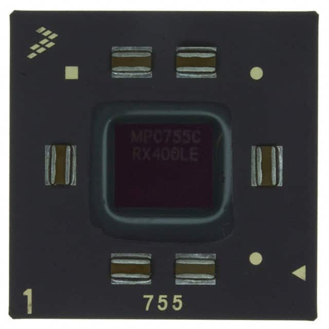
- Part No.:
- MPC755BRX300LE
- Manufacturer:
- NXP Semiconductors
- Category:
- Microprocessors
- Package:
- 360-BCBGA, FCCBGA
- Datasheet:
-
 MPC755BRX300LE.pdf
- Description:
- IC MPU MPC7XX 300MHZ 360CBGA
- Quantity:
- Payment:

- Shipping:

Inventory:3,962
Please send an inquiry. Send us your inquiry, and we will respond immediately.
Product details
Overview
MPC755BRX300LE from Freescale Semiconductor is a 300 MHz PowerPC™ RISC microprocessor implementing the 60x bus architecture, featuring a 32 KB instruction cache, 32 KB data cache, integrated L2 cache controller, and support for doze/nap/sleep power management modes. It operates at 2.0 V core voltage with 2.5 V or 3.3 V I/O supply and targets embedded control and communications infrastructure applications.
For engineers reviewing the MPC755BRX300LE datasheet, MPC755BRX300LE pinout, MPC755BRX300LE application, or MPC755BRX300LE equivalent, key selection considerations include its 360-ball CBGA package, 300 MHz core frequency with 25–100 MHz SYSCLK range, L2 cache interface capability, thermal sensor integration, and compatibility with MPC750-family software and toolchains.
Technical Context
The MPC755BRX300LE implements a dual-issue, out-of-order execution PowerPC core with branch prediction (512-entry BHT), two fixed-point units, one floating-point unit, and hardware-managed MEI cache coherency. Its 60x bus interface supports 32-bit addressing and 64-bit data transfers with configurable bus-to-core multipliers (2x–10x).
It integrates an on-die thermal management assist unit (TAU) with ±12°C accuracy digital thermal sensor, dedicated SPRs for junction temperature monitoring, and interrupt-driven thermal regulation. The L2 cache interface supports external synchronous BurstRAMs (256 KB–1 MB, two-way set-associative) with configurable line sizes and core-to-L2 divisors (÷1 to ÷3).
Key Specifications
| Parameter | Value and Actual Design Meaning |
|---|---|
| Core Frequency | 300 MHz - Fixed maximum operating speed; determines real-time throughput and instruction dispatch rate in embedded control loops. |
| Core Supply Voltage | 1.80–2.10 V - Tight 300 mV tolerance enables stable operation under dynamic load; lower end supports reduced-power operation without derating. |
| L1 Cache | 32 KB instruction + 32 KB data, 8-way set-associative - Enables single-cycle cache access and nonblocking misses for deterministic latency in real-time firmware. |
| L2 Interface | 64-bit data bus, 17-bit address bus, ÷1/÷1.5/÷2/÷2.5/÷3 divisors - Allows flexible bandwidth matching between CPU core and external SRAM-based L2 cache subsystems. |
| Thermal Sensor Accuracy | ±12°C - Provides sufficient resolution for software-triggered thermal throttling in fanless industrial enclosures without external sensors. |
| Power in Sleep Mode | 550 mW - Enables low-energy standby in network edge devices requiring periodic wake-up via interrupt or timer event. |
| Package Type | 360-ball Ceramic BGA (CBGA) - Offers superior thermal conductivity and long-term reliability vs. PBGA for high-temperature industrial deployments. |
Pinout & Package
Package: 360-ball Ceramic Ball Grid Array (CBGA), 27 mm × 27 mm, 1.27 mm pitch, RoHS-compliant. Thermal resistance RθJA = 24°C/W (natural convection, single-layer board).
| Pin/Terminal | Circuit Role | Design Meaning |
|---|---|---|
| HRESET | Asynchronous reset input | Active-low signal that initializes all internal registers and state machines; must be held asserted ≥255 bus clocks after PLL lock during power-on. |
| SYSCLK | Primary clock input | Differential-capable single-ended clock input (25–100 MHz); defines bus timing and drives PLL to generate 300 MHz core frequency. |
| BVSEL | I/O voltage select | Configures processor bus interface threshold: logic 0 = 2.5 V, logic 1 = 3.3 V; must remain stable during operation. |
| L2VSEL | L2 bus voltage select | Configures L2 bus interface threshold independently of BVSEL; enables mixed-voltage system integration. |
| PLL_CFG[0:3] | PLL configuration inputs | Four-pin strap defining bus-to-core multiplier (e.g., 3x for 100 MHz SYSCLK → 300 MHz core); must be latched at HRESET deassertion. |
| THRM_INT | Thermal interrupt output | Open-drain signal asserted when junction temperature exceeds software-configured threshold; used for OS-level thermal management. |
Key Features
| Feature | Design Value |
|---|---|
| Out-of-order execution with 6-entry reorder buffer | Enables instruction-level parallelism across independent code paths while preserving program-order completion for exception safety. |
| Hardware TLB reload (128-entry I/D TLB) | Eliminates software tablewalk overhead for virtual-to-physical address translation in real-time OS contexts. |
| Copy-back or write-through L1 data cache (page-selectable) | Allows optimization for either memory bandwidth efficiency (copy-back) or cache coherency simplicity (write-through) per memory region. |
| JTAG/COP debug interface (IEEE 1149.1) | Supports boundary-scan testing, in-circuit emulation, and non-intrusive firmware debugging without halting real-time tasks. |
| Dynamic power management with four sleep states | Permits fine-grained energy control: doze (clock-gated core), nap (core + bus idle), sleep (PLL off), and deep sleep (PLL + DLL off). |
Applications
| Industrial PLC Controller | Telecom Line Card |
|---|---|
Use Scenario: Real-time motion control loop executing at 1 kHz with deterministic I/O scanning and EtherCAT master stack. IC Role / Device Role / Timing Role: Primary application processor managing fieldbus protocol stacks, servo axis coordination, and safety logic execution. Use Value: 300 MHz core + L1 cache + hardware TLB ensures sub-10 µs worst-case interrupt latency and jitter-free cycle timing for synchronized drive control. |
Use Scenario: Multi-port TDM switching and packet classification in carrier-grade DSLAM line cards. IC Role / Device Role / Timing Role: Control-plane processor handling OAM, provisioning, and statistics collection while offloading data-plane to ASICs. Use Value: 60x bus interface enables direct connection to high-speed FIFOs and shared memory with telecom PHYs; L2 cache interface accelerates packet metadata lookups. |
| Avionics Data Concentrator | Medical Imaging Subsystem |
Use Scenario: ARINC 429/664 (AFDX) message aggregation and health monitoring in flight control computers. IC Role / Device Role / Timing Role: Safety-critical host processor executing DO-254/DO-178C-certified firmware with partitioned memory and watchdog supervision. Use Value: CBGA package provides proven reliability under thermal cycling; integrated thermal sensor enables runtime junction temperature validation per certification requirements. |
Use Scenario: DICOM image preprocessing pipeline (windowing, histogram equalization, ROI extraction) in portable ultrasound systems. IC Role / Device Role / Timing Role: Embedded vision coprocessor performing real-time pixel math using FP unit and cache-local buffers. Use Value: IEEE 754-compliant FPU with denormal support ensures numerical consistency across medical algorithm implementations; low-power sleep modes extend battery life. |
Equivalent & Alternatives
The following parts are listed as comparable options for similar RISC microprocessor applications.
| Alternative Part | Technical Difference | Application Difference | Selection Advice |
|---|---|---|---|
| MPC745BRX300LE | No L2 cache interface; identical core, cache, and bus architecture otherwise. | Lower-cost designs omitting external L2 cache; suitable where L1 cache suffices for working set size. | Select MPC745BRX300LE only if L2 expansion is unnecessary and BOM cost reduction is prioritized over future scalability. |
| MPC755BRX350LE | 350 MHz core frequency; same package, voltage, and feature set; higher power consumption (6.0 W max vs. 4.5 W). | Applications requiring higher deterministic throughput, such as multi-threaded protocol stacks or faster FFT processing. | Choose MPC755BRX350LE when 300 MHz fails timing closure in critical paths but PCB layout and thermal design accommodate increased dissipation. |
Compared with MPC745BRX300LE, MPC755BRX300LE adds L2 cache interface capability for scalable memory bandwidth; compared with MPC755BRX350LE, it trades 50 MHz peak performance for 1.5 W lower full-power dissipation and relaxed thermal design margins.
Availability
MPC755BRX300LE is available at Aetrix Electronics and suitable for industrial automation, telecom infrastructure, avionics, and medical imaging systems requiring stable component supply, long-lifecycle support, and traceable ceramic-packaged microprocessors.
Supply support for MPC755BRX300LE includes scheduled delivery planning, volume procurement assistance, BOM continuity management, traceable sourcing, and lifecycle availability coordination for OEM customers, industrial embedded developers, connected-device designers, and electronics production programs.
Manufacturer
Freescale Semiconductor (now part of NXP Semiconductors) was a leading designer of embedded processors, analog, and connectivity solutions for automotive, industrial, and networking markets.
The MPC755BRX300LE belongs to the PowerPC 7xx family, engineered for high-reliability embedded control applications demanding deterministic real-time performance, low-power operation, and hardware-assisted virtual memory management.
FAQ
What is the maximum supported L2 cache size for MPC755BRX300LE?
The MPC755BRX300LE supports up to 1 MB of external two-way set-associative L2 cache via its dedicated interface. This is implemented using synchronous BurstRAMs with 64-byte (256 KB/512 KB) or 128-byte (1 MB) sectored line sizes. The L2 controller handles tag storage internally, and cache mode (instruction-only, data-only, or split) is configurable in real time through L2CR register writes. MPC755BRX300LE does not integrate L2 SRAM on-die.
Does MPC755BRX300LE support little-endian operation?
Yes, MPC755BRX300LE fully supports both big-endian and little-endian byte ordering for data accesses, controlled dynamically via the MSR[LE] bit. This enables binary compatibility with legacy PowerPC code (big-endian) and interoperability with x86-derived peripherals or software stacks requiring little-endian alignment. Instruction fetch remains big-endian only, per PowerPC architecture specification.
Can MPC755BRX300LE operate with 1.8 V core voltage?
Yes, MPC755BRX300LE is rated for core supply (VDD) between 1.80 V and 2.10 V at 300 MHz operation, as specified in Table 3 of the hardware specifications. Operation at 1.8 V is validated and supported, delivering reduced dynamic power consumption while maintaining full timing compliance. However, AVDD and L2AVDD must also be supplied within their respective 1.80–2.10 V range when VDD = 1.8 V.
Is MPC755BRX300LE pin-compatible with MPC745BRX300LE?
No, MPC755BRX300LE and MPC745BRX300LE are not pin-compatible. While both use 360-ball packages, MPC755BRX300LE requires the ceramic BGA (CBGA) variant, whereas MPC745BRX300LE is only offered in plastic BGA (PBGA). More critically, MPC755BRX300LE allocates pins for L2 address/data/control signals (e.g., L2AD[0:16], L2D[0:63], L2CLK) that are NC on MPC745BRX300LE, making direct PCB substitution impossible without redesign.
What debug interfaces does MPC755BRX300LE provide?
MPC755BRX300LE provides IEEE 1149.1 JTAG boundary-scan and COP (Controller On Processor) interfaces. JTAG supports scan-chain access for manufacturing test and basic register visibility; COP enables full in-circuit emulation including breakpoints, watchpoints, and real-time trace via dedicated COP pins. Both interfaces operate independently of CPU execution state, allowing non-intrusive debugging even during hard faults or real-time task execution.
MPC755BRX300LE Specifications
- Product attributes
- Attribute value
- Manufacturer:
- NXP Semiconductors
- Package/Case:
- 360-BCBGA, FCCBGA
- Series:
- MPC7xx
- Packaging:
- Tray
- Product Status:
- Obsolete
- Core Processor:
- PowerPC
- Number of Cores/Bus Width:
- 1 Core, 32-Bit
- Speed:
- 300MHz
- Co-Processors/DSP:
- -
- RAM Controllers:
- -
- Graphics Acceleration:
- No
- Display & Interface Controllers:
- -
- Ethernet:
- -
- SATA:
- -
- USB:
- -
- Voltage - I/O:
- 2.5V, 3.3V
- Operating Temperature:
- 0°C ~ 105°C (TA)
- Grade:
- -
- Qualification:
- -
- Security Features:
- -
- Mounting Type:
- Surface Mount
- Supplier Device Package:
- 360-CBGA (25x25)
- Additional Interfaces:
- -
MPC755BRX300LE FAQ
1.How can I place an order for MPC755BRX300LE through Aetrix?
Please submit a Request for Quotation (RFQ) for MPC755BRX300LE on Aetrix. Our sales agent will provide a competitive quotation and guide you through the order confirmation once you accept the terms.
2.Are the price and stock information for MPC755BRX300LE reliable?
The price and inventory of MPC755BRX300LE are updated periodically and may fluctuate due to market conditions. Stock and pricing data are typically refreshed every 24 hours. Quotation validity for MPC755BRX300LE is usually 5 days.
3.What payment methods are accepted for MPC755BRX300LE?
We accept Wire Transfer, PayPal, Credit Card, Western Union, MoneyGram, and Escrow for MPC755BRX300LE transactions.
Note: Certain payment methods may incur a processing fee.
4.How is shipping managed for MPC755BRX300LE?
MPC755BRX300LE orders can be shipped via leading logistics carriers, including DHL, UPS, FedEx, TNT, or Registered Mail.
Once your MPC755BRX300LE order is processed, you will receive an email with the shipment details and tracking number.
Note: Tracking information may take up to 24 hours to appear. Express delivery typically takes 3–5 business days.
5.How can I obtain technical support or documentation for MPC755BRX300LE?
For technical support, including MPC755BRX300LE datasheets, pinout diagrams, or application guidance, please contact our engineering support team. They can provide detailed documentation and assistance for your MPC755BRX300LE requirements.
6.How does Aetrix verify that MPC755BRX300LE is sourced from the original manufacturer or authorized distributors?
All MPC755BRX300LE products on Aetrix are procured from qualified distributors and authorized channels. Our dedicated quality assurance team conducts strict verification, including traceability checks and, if necessary, third-party testing. This ensures that MPC755BRX300LE meets industry standards.
7.What is the process for return or replacement of MPC755BRX300LE?
All MPC755BRX300LE units undergo pre-shipment inspection (PSI). If there is an issue with MPC755BRX300LE, returns or replacements are accepted under the following conditions:
1.Quantity discrepancies, incorrect items, or visible external defects (such as breakage or corrosion), acknowledged by Aetrix.
2.The issue is reported within 90 days of delivery.
3.The MPC755BRX300LE part is unused and in its original packaging.
Return procedure for MPC755BRX300LE:
1.Submit a request within 90 days.
2.Obtain a Return Material Authorization (RMA) from Aetrix.
MPC755BRX300LE Tags

-
AT91SAM9260B-CU-999
Microchip Technology
-
AT91SAM9G25-CU
Microchip Technology

-
ATSAMA5D27C-CU
Microchip Technology
-
AT91SAM9X35-CU
Microchip Technology
-
AT91SAM9X25-CU
Microchip Technology

-
MCIMX6Y2CVM08AB
NXP Semiconductors
.JPG)
-
AM3352BZCZ100
Texas Instruments
-
AT91SAM9260B-CU
Microchip Technology

-
AT91SAM9260B-QU
Microchip Technology

-
ATSAMA5D31A-CU
Microchip Technology
-
AT91SAM9G20B-CU-999
Microchip Technology
-
MCIMX6Y2CVM05AB
NXP Semiconductors
Tech Hub

A practical engineering guide to 3.3V and 5V logic compatibility, input thresholds, resistor dividers, translator ICs, MOSFET level shifting, I2C pull-ups, timing limits and power-sequencing risks.

The 74HC595 uses push-pull logic outputs, while the TPIC6B595 uses 50 V open-drain DMOS sinks for higher-power loads. This guide compares timing, current limits, 3.3 V interfacing, load wiring, thermal…

The 74HC595 converts serial data into eight stable parallel outputs. This guide covers pin functions, shift and storage timing, OE and MR behavior, drive-current limits, cascading, voltage compatibilit…

A technical comparison of level-sensitive latches and edge-triggered flip-flops, covering timing windows, setup and hold limits, master–slave operation, time borrowing, race-through, HDL inference and…

A D latch stores one bit while Enable controls when data can pass. This reference covers gate-level operation, truth tables, transparency, setup and hold timing, LE versus OE, common ICs and practical …

An SR latch stores one bit through cross-coupled feedback. This engineering reference covers NOR and NAND implementations, truth tables, forbidden-state recovery, gated operation, switch debouncing, fa…

Latch circuits retain one bit through feedback. This technical reference covers SR and D latches, truth tables, transparency, timing limits, latch-versus-flip-flop behavior, applications and common log…

An engineering guide to LED driver operation, constant-current and constant-voltage outputs, linear and switching topologies, dimming, IC selection, calculations, replacement compatibility, and fault c…

Operational amplifier guide covering op amp basics, feedback, ideal vs real op amps, common configurations, buffer circuits, offset, bias current, gain-bandwidth, slew rate, rail-to-rail limits and sel…

Jumper cables guide covering safe connection order, red and black clamp placement, final ground connection, cable gauge, length, clamp quality, copper vs CCA cables, jump starter comparison and battery…


