
 My Inquiry
 My Account


NXP Semiconductors MPC755BVT300LE
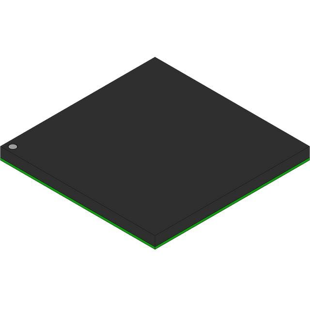
- Part No.:
- MPC755BVT300LE
- Manufacturer:
- NXP Semiconductors
- Category:
- Microprocessors
- Package:
- 360-BBGA, FCBGA
- Datasheet:
-
 MPC755BVT300LE.pdf
- Description:
- IC MPU MPC7XX 300MHZ 360FCPBGA
- Quantity:
- Payment:

- Shipping:

Inventory:3,421
Please send an inquiry. Send us your inquiry, and we will respond immediately.
Product details
Overview
MPC755BVT300LE from NXP Semiconductors (formerly Freescale) is a 300 MHz PowerPC™ RISC microprocessor implementing the 60x bus architecture, featuring integrated L2 cache controller, 32 KB instruction and data L1 caches, and hardware-supported power management modes (doze, nap, sleep). It targets embedded control and networking applications requiring deterministic real-time performance with thermal-aware operation.
For engineers reviewing the MPC755BVT300LE datasheet, MPC755BVT300LE pinout, MPC755BVT300LE application, or MPC755BVT300LE equivalent, key selection criteria include its 360-ball CBGA package, 2.0 V core supply with ±100 mV tolerance, 25–100 MHz SYSCLK input range, L2 interface supporting up to 1 MB two-way set-associative cache, and on-die thermal sensor with ±12°C accuracy.
Technical Context
The MPC755BVT300LE implements a superscalar, out-of-order execution PowerPC core with dual fixed-point units, a pipelined floating-point unit compliant with IEEE 754, and dual 32 KB eight-way set-associative L1 caches. Its 60x bus interface supports 32-bit addressing and 64-bit data transfers at configurable bus-to-core ratios (2x–10x).
It integrates an L2 cache controller with dedicated 17-bit address and 64-bit data buses, supporting synchronous BurstRAMs in flow-through or pipelined modes. The on-die Thermal Assist Unit (TAU) includes a calibrated junction temperature sensor, comparator, and dedicated SPRs for software-regulated thermal management.
Key Specifications
| Parameter | Value and Actual Design Meaning |
|---|---|
| Core Frequency | 300 MHz - Fixed maximum operating frequency; determines instruction throughput and real-time latency bounds. |
| L1 Cache | 32 KB instruction + 32 KB data, eight-way set-associative - Enables single-cycle cache access and reduces memory stall cycles in interrupt-driven control loops. |
| L2 Interface | Dedicated controller with 64-bit data/17-bit address bus - Supports external SRAM-based L2 cache up to 1 MB; not present on MPC745 variant. |
| Power Modes | Doze, nap, sleep - Reduce dynamic and leakage power; sleep mode draws ≤550 mW, enabling low-power standby in network edge devices. |
| Thermal Sensor | On-die junction sensor with ±12°C accuracy and 4°C resolution - Provides direct die-temperature feedback for closed-loop thermal throttling without external components. |
| Bus Interface | 60x-compliant, 32-bit address / 64-bit data, selectable 2.5 V or 3.3 V I/O - Ensures interoperability with legacy PowerPC system controllers and memory subsystems. |
| Package | 360-ball ceramic BGA (CBGA), 27 mm × 27 mm - Offers superior thermal dissipation (RθJA = 24°C/W) and long-term reliability vs. PBGA for industrial environments. |
Pinout & Package
Package: 360-ball Ceramic Ball Grid Array (CBGA), 27 mm × 27 mm, 1.27 mm ball pitch, RoHS-compliant. Designed for high-reliability industrial and telecom applications with enhanced thermal and mechanical stability over plastic alternatives.
| Pin/Terminal | Circuit Role | Design Meaning |
|---|---|---|
| VDD | Core power supply | 2.0 V ±100 mV DC input; powers processor core logic; must be stable before HRESET release. |
| OVDD | Processor bus I/O supply | Selectable 2.5 V or 3.3 V; sets voltage threshold for 60x bus signals via BVSEL pin sampling. |
| L2OVDD | L2 bus I/O supply | Selectable 2.5 V or 3.3 V; independently configured from OVDD using L2VSEL pin. |
| SYSCLK | System clock input | 25–100 MHz differential-capable single-ended clock; drives PLL to generate 300 MHz core frequency. |
| HRESET | Hardware reset input | Asynchronous active-low reset; must be held for ≥255 bus clocks after PLL lock during power-on sequence. |
| THRM_INT | Thermal interrupt output | Open-drain signal asserted when junction temperature exceeds software-configured TAU threshold. |
Key Features
| Feature | Design Value |
|---|---|
| Branch Prediction | 512-entry BHT + 64-entry BTIC - Reduces pipeline stalls from conditional branches in real-time control firmware. |
| Floating-Point Unit | IEEE 754 single/double precision with hardware divide and denormal support - Enables deterministic math in motor control and signal processing without software emulation. |
| Memory Management | 128-entry dual TLB + 8 BATs + 4 GB physical addressing - Simplifies OS porting and enables MMU-based memory protection in safety-critical systems. |
| JTAG Debug | IEEE 1149.1 compliant interface - Supports boundary scan testing and in-circuit debugging via COP/JTAG without requiring external debug probes. |
| Cache Coherency | Hardware-enforced MEI protocol for L1 data cache - Eliminates need for software cache flushes during multi-master bus arbitration in shared-memory systems. |
Applications
| Industrial PLC Controller | Telecom Line Card |
|---|---|
|
Use Scenario: Real-time motion control in servo drives with multi-axis coordination and fieldbus (CANopen, Profibus) interfacing. IC Role / Device Role / Timing Role: Main application processor executing deterministic control loops, managing L1/L2 cache hierarchy for low-latency I/O buffering, and regulating thermal headroom via TAU interrupts. Use Value: 300 MHz core + hardware FP unit delivers sub-10 µs jitter in PID loop execution; L2 interface enables local SRAM caching of encoder position buffers to avoid DDR latency. |
Use Scenario: Packet classification and forwarding engine in carrier-grade DSLAM line cards with QoS enforcement. IC Role / Device Role / Timing Role: Control-plane processor handling SNMP, CLI, and configuration management while offloading data-path tasks to ASICs; uses 60x bus for high-bandwidth control register access. Use Value: 64-bit 60x bus at 100 MHz provides 800 MB/s bandwidth to manage multiple PHY registers; doze mode reduces idle power by >50% during low-traffic periods. |
| Avionics Data Concentrator | Medical Imaging Subsystem |
|
Use Scenario: ARINC 429/664 data aggregation unit in flight control computers requiring DO-254 compliance and extended temperature operation. IC Role / Device Role / Timing Role: Safety-critical host processor executing partitioned ARINC stacks; leverages L1 cache locking to guarantee worst-case execution time (WCET) for critical partitions. Use Value: CBGA package ensures -55°C to +105°C junction operation; hardware TLB reload and BATs enable fast context switching between certified partitions without software tablewalk overhead. |
Use Scenario: Image reconstruction co-processor in ultrasound systems performing beamforming and FFT-based filtering. IC Role / Device Role / Timing Role: Dedicated compute engine running fixed/floating-point kernels; uses L2 interface to stream raw ADC data from FPGA-accelerated front-end into local SRAM cache. Use Value: Single-cycle L1 cache access + 3-cycle FP multiply-add latency enables real-time 2D FFT computation; thermal sensor triggers automatic clock scaling before reaching 105°C junction limit. |
Equivalent & Alternatives
The following parts are listed as comparable options for similar RISC microprocessor applications.
| Alternative Part | Technical Difference | Application Difference | Selection Advice |
|---|---|---|---|
| MPC745BVT300LE | Lacks L2 cache interface; identical core, L1 caches, and power management features. | Suitable only where external L2 cache is unnecessary or implemented via alternate bus masters. | Select MPC745BVT300LE when system design omits L2 SRAM and prioritizes cost reduction over cache bandwidth. |
| MPC7447A | Higher-performance 1.0 GHz PowerPC core; 256 KB on-die L2 cache; supports AltiVec SIMD instructions. | Targets computationally intensive applications like video encoding; requires different PCB layout and thermal solution. | Choose MPC7447A only when existing MPC755BVT300LE firmware can be recompiled for AltiVec and thermal budget allows >10 W dissipation. |
Compared with MPC755BVT300LE, MPC745BVT300LE removes L2 interface capability but retains identical pinout and power envelope, while MPC7447A increases peak throughput fivefold at the cost of doubled power draw and incompatible cache architecture - making MPC755BVT300LE optimal for thermally constrained, cache-sensitive embedded control where deterministic latency outweighs raw speed.
Availability
MPC755BVT300LE is available at Aetrix Electronics and suitable for industrial PLC controllers, telecom line cards, avionics data concentrators, and medical imaging subsystems requiring stable component supply across extended product lifecycles.
Supply support for MPC755BVT300LE includes scheduled delivery planning, volume procurement assistance, BOM continuity management, traceable sourcing, and lifecycle availability coordination for OEM customers, industrial embedded developers, connected-device designers, and electronics production programs.
Manufacturer
NXP Semiconductors is a global semiconductor leader focused on secure connectivity solutions for automotive, industrial, and IoT applications, with deep heritage in Power Architecture® technology.
The MPC755BVT300LE belongs to NXP's PowerPC 7xx family, designed specifically for high-reliability embedded control systems demanding low-power operation, hardware-assisted thermal management, and deterministic real-time performance in harsh environments.
FAQ
What is the maximum supported L2 cache size for MPC755BVT300LE?
The MPC755BVT300LE supports external L2 cache sizes of 256 KB, 512 KB, or 1 MB in two-way set-associative configuration. Its L2 interface uses a 17-bit address bus and 64-bit data bus, with configurable line sizes (64-byte for 256/512 KB, 128-byte for 1 MB) and support for synchronous BurstRAM timing modes including 3-1-1-1 and strobeless 4-1-1-1. This capability is absent in the MPC745 variant.
Does MPC755BVT300LE require external voltage regulators for all power domains?
Yes, MPC755BVT300LE requires three independent regulated supplies: VDD (2.0 V ±100 mV) for the core, OVDD (2.5 V or 3.3 V) for the 60x bus I/O, and L2OVDD (2.5 V or 3.3 V) for the L2 bus I/O. Each domain has separate pins and decoupling requirements specified in Section 4.1 of the hardware specifications. The PLL and L2 DLL also require dedicated AVDD and L2AVDD supplies at 1.8–2.1 V.
How does the Thermal Assist Unit (TAU) in MPC755BVT300LE function in practice?
The MPC755BVT300LE TAU integrates an on-die thermal sensor with ±12°C accuracy and 4°C resolution, feeding raw data to dedicated SPRs (THRM0–THRM3). Software reads these registers and applies calibration coefficients from AN1800/D to derive absolute junction temperature. When thresholds are exceeded, THRM_INT asserts to trigger OS-level throttling - such as reducing bus frequency or entering nap mode - without external sensors or analog circuitry.
Is MPC755BVT300LE pin-compatible with other members of the MPC7xx family?
MPC755BVT300LE shares the same 360-ball CBGA footprint and pin assignments with MPC755 variants (e.g., MPC755BVT350LE, MPC755BVT400LE) but is not pin-compatible with MPC745 (which uses 255-ball PBGA) or MPC7447A (which uses 516-ball PBGA). Signal-level compatibility exists with MPC750-series processors on the 60x bus, but voltage thresholds and timing parameters differ per speed grade and revision.
What boot configuration options are available for MPC755BVT300LE at power-on reset?
At power-on, MPC755BVT300LE samples BVSEL and L2VSEL pins to configure I/O voltage thresholds (2.5 V or 3.3 V), and PLL_CFG[0:3] pins to set bus-to-core frequency multiplication (e.g., 3x for 300 MHz core from 100 MHz SYSCLK). These pins must remain stable after HRESET assertion; changing them during operation violates specification and may cause bus timing violations or PLL unlock.
MPC755BVT300LE Specifications
- Product attributes
- Attribute value
- Manufacturer:
- NXP Semiconductors
- Package/Case:
- 360-BBGA, FCBGA
- Series:
- MPC7xx
- Packaging:
- Tray
- Product Status:
- Obsolete
- Core Processor:
- PowerPC
- Number of Cores/Bus Width:
- 1 Core, 32-Bit
- Speed:
- 300MHz
- Co-Processors/DSP:
- -
- RAM Controllers:
- -
- Graphics Acceleration:
- No
- Display & Interface Controllers:
- -
- Ethernet:
- -
- SATA:
- -
- USB:
- -
- Voltage - I/O:
- 2.5V, 3.3V
- Operating Temperature:
- 0°C ~ 105°C (TA)
- Grade:
- -
- Qualification:
- -
- Security Features:
- -
- Mounting Type:
- Surface Mount
- Supplier Device Package:
- 360-FCPBGA (25x25)
- Additional Interfaces:
- -
MPC755BVT300LE FAQ
1.How can I place an order for MPC755BVT300LE through Aetrix?
Please submit a Request for Quotation (RFQ) for MPC755BVT300LE on Aetrix. Our sales agent will provide a competitive quotation and guide you through the order confirmation once you accept the terms.
2.Are the price and stock information for MPC755BVT300LE reliable?
The price and inventory of MPC755BVT300LE are updated periodically and may fluctuate due to market conditions. Stock and pricing data are typically refreshed every 24 hours. Quotation validity for MPC755BVT300LE is usually 5 days.
3.What payment methods are accepted for MPC755BVT300LE?
We accept Wire Transfer, PayPal, Credit Card, Western Union, MoneyGram, and Escrow for MPC755BVT300LE transactions.
Note: Certain payment methods may incur a processing fee.
4.How is shipping managed for MPC755BVT300LE?
MPC755BVT300LE orders can be shipped via leading logistics carriers, including DHL, UPS, FedEx, TNT, or Registered Mail.
Once your MPC755BVT300LE order is processed, you will receive an email with the shipment details and tracking number.
Note: Tracking information may take up to 24 hours to appear. Express delivery typically takes 3–5 business days.
5.How can I obtain technical support or documentation for MPC755BVT300LE?
For technical support, including MPC755BVT300LE datasheets, pinout diagrams, or application guidance, please contact our engineering support team. They can provide detailed documentation and assistance for your MPC755BVT300LE requirements.
6.How does Aetrix verify that MPC755BVT300LE is sourced from the original manufacturer or authorized distributors?
All MPC755BVT300LE products on Aetrix are procured from qualified distributors and authorized channels. Our dedicated quality assurance team conducts strict verification, including traceability checks and, if necessary, third-party testing. This ensures that MPC755BVT300LE meets industry standards.
7.What is the process for return or replacement of MPC755BVT300LE?
All MPC755BVT300LE units undergo pre-shipment inspection (PSI). If there is an issue with MPC755BVT300LE, returns or replacements are accepted under the following conditions:
1.Quantity discrepancies, incorrect items, or visible external defects (such as breakage or corrosion), acknowledged by Aetrix.
2.The issue is reported within 90 days of delivery.
3.The MPC755BVT300LE part is unused and in its original packaging.
Return procedure for MPC755BVT300LE:
1.Submit a request within 90 days.
2.Obtain a Return Material Authorization (RMA) from Aetrix.
MPC755BVT300LE Tags

-
AT91SAM9260B-CU-999
Microchip Technology
-
AT91SAM9G25-CU
Microchip Technology

-
ATSAMA5D27C-CU
Microchip Technology
-
AT91SAM9X35-CU
Microchip Technology
-
AT91SAM9X25-CU
Microchip Technology

-
MCIMX6Y2CVM08AB
NXP Semiconductors
.JPG)
-
AM3352BZCZ100
Texas Instruments
-
AT91SAM9260B-CU
Microchip Technology

-
AT91SAM9260B-QU
Microchip Technology

-
ATSAMA5D31A-CU
Microchip Technology
-
AT91SAM9G20B-CU-999
Microchip Technology
-
MCIMX6Y2CVM05AB
NXP Semiconductors
Tech Hub

A practical engineering guide to 3.3V and 5V logic compatibility, input thresholds, resistor dividers, translator ICs, MOSFET level shifting, I2C pull-ups, timing limits and power-sequencing risks.

The 74HC595 uses push-pull logic outputs, while the TPIC6B595 uses 50 V open-drain DMOS sinks for higher-power loads. This guide compares timing, current limits, 3.3 V interfacing, load wiring, thermal…

The 74HC595 converts serial data into eight stable parallel outputs. This guide covers pin functions, shift and storage timing, OE and MR behavior, drive-current limits, cascading, voltage compatibilit…

A technical comparison of level-sensitive latches and edge-triggered flip-flops, covering timing windows, setup and hold limits, master–slave operation, time borrowing, race-through, HDL inference and…

A D latch stores one bit while Enable controls when data can pass. This reference covers gate-level operation, truth tables, transparency, setup and hold timing, LE versus OE, common ICs and practical …

An SR latch stores one bit through cross-coupled feedback. This engineering reference covers NOR and NAND implementations, truth tables, forbidden-state recovery, gated operation, switch debouncing, fa…

Latch circuits retain one bit through feedback. This technical reference covers SR and D latches, truth tables, transparency, timing limits, latch-versus-flip-flop behavior, applications and common log…

An engineering guide to LED driver operation, constant-current and constant-voltage outputs, linear and switching topologies, dimming, IC selection, calculations, replacement compatibility, and fault c…

Operational amplifier guide covering op amp basics, feedback, ideal vs real op amps, common configurations, buffer circuits, offset, bias current, gain-bandwidth, slew rate, rail-to-rail limits and sel…

Jumper cables guide covering safe connection order, red and black clamp placement, final ground connection, cable gauge, length, clamp quality, copper vs CCA cables, jump starter comparison and battery…


