
 My Inquiry
 My Account


NXP Semiconductors MPC8306SCVMACDCA
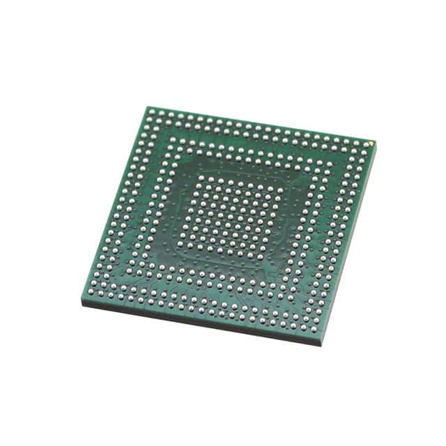
- Part No.:
- MPC8306SCVMACDCA
- Manufacturer:
- NXP Semiconductors
- Category:
- Microprocessors
- Package:
- 369-LFBGA
- Datasheet:
-
 MPC8306SCVMACDCA.pdf
- Description:
- IC MPU MPC83XX 200MHZ 369BGA
- Quantity:
- Payment:

- Shipping:

Inventory:4,396
Please send an inquiry. Send us your inquiry, and we will respond immediately.
Product details
Overview
MPC8306SCVMACDCA from NXP Semiconductors (formerly Freescale) is a PowerQUICC II Pro integrated communications processor built on Power Architecture® technology, featuring an e300c3 core with 16 KB instruction and 16 KB data caches, dual integer units, and MMU support. It integrates a 16-bit DDR2 SDRAM controller (266 MHz data rate), five Unified Communication Controllers (UCCs) supporting 10/100 Mbps Ethernet via MII/RMII, HDLC, and TDM, and a QUICC Engine™ block with 48 KB instruction RAM and 16 KB multiuser RAM. It targets residential gateways and industrial control systems requiring deterministic real-time protocol handling.
For engineers reviewing the MPC8306SCVMACDCA datasheet, MPC8306SCVMACDCA pinout, MPC8306SCVMACDCA application, or MPC8306SCVMACDCA equivalent, key selection considerations include its 133–333 MHz e300c3 core frequency range, 1.0 V ±50 mV core supply requirement, 1.8 V DDR2 I/O voltage, 3.3 V general-purpose I/O voltage, and support for boot from parallel NOR/NAND Flash - all critical for embedded networking hardware design and migration from legacy PowerQUICC platforms.
Technical Context
The MPC8306SCVMACDCA implements a dual-domain clock architecture: the e300c3 core operates at up to 333 MHz using a dedicated PLL driven by SYS_CLK_IN (24–66.67 MHz), while the QUICC Engine runs independently at up to 233 MHz with its own PLL - enabling power-optimized concurrent processing of network protocols and application code. Its DDR2 controller supports 14 address lines, two chip selects, and up to 2-Gbit x16 devices with auto-refresh and CKE-based power management.
The device uses a hierarchical interrupt system via the Integrated Programmable Interrupt Controller (IPIC), offering six priority groups and vectorized routing for both internal peripherals (UCCs, USB, DUART, timers) and external sources. All five UCCs are software-configurable for MII/RMII Ethernet, HDLC, or TDM - with TDM supporting up to 128 channels at 64 kbps each - and share access to the QUICC Engine's serial DMA engines for zero-copy packet handling.
Key Specifications
| Parameter | Value and Actual Design Meaning |
|---|---|
| e300c3 Core Frequency | 133–333 MHz; determines maximum instruction throughput and real-time response latency in control-plane tasks |
| DDR2 Interface | 16-bit bus, 266 MHz data rate; supports up to 512 MB total memory across two banks with programmable timing |
| QUICC Engine Frequency | 133–233 MHz; enables concurrent offloading of Ethernet frame processing, HDLC framing, and TDM time-slot assignment |
| UCC Count | 5 independent controllers; each configurable as MII/RMII Ethernet, HDLC, or TDM port - no hardware multiplexing required |
| I/O Supply Voltages | VDD = 1.0 V ±50 mV (core), GVDD = 1.8 V ±100 mV (DDR2), OVDD = 3.3 V ±300 mV (peripherals); mandates separate low-noise LDOs |
| Package | 620-ball PBGA (35 mm × 35 mm, 1.0 mm pitch); requires controlled-impedance PCB stackup for DDR2 and RMII signal integrity |
| Thermal Range | 0 °C to 105 °C junction temperature; validated for fanless industrial enclosure operation without derating at full frequency |
Pinout & Package
Package: 620-ball plastic ball grid array (PBGA), 35 mm × 35 mm body, 1.0 mm ball pitch, RoHS-compliant lead-free finish. Thermal pad on underside requires solder paste stencil opening and thermal via array for junction-to-board heat transfer.
| Pin/Terminal | Circuit Role | Design Meaning |
|---|---|---|
| SYS_CLK_IN | Primary system clock input | Accepts 24–66.67 MHz single-ended CMOS clock; must meet ≤2.8 ns rise/fall time and ±150 ps jitter for stable PLL lock |
| HRESET | Hardware reset input | Active-low asynchronous reset; requires ≥32 SYS_CLK_IN cycles assertion before release to initialize IPIC, DDR controller, and QUICC Engine |
| PORESET | Power-on reset input | Monitors power rail stability; must be held active until VDD reaches 90% nominal and GVDD/OVDD exceed 0.7 V |
| MCK / MCK | DDR2 memory clock pair | Differential 133 MHz clock output driving DDR2 SDRAM; skew between MCK and MDQS must be ≤±0.6 ns for reliable DQ capture |
| MDQ[15:0] | DDR2 bidirectional data bus | 16-bit data interface with on-die termination; requires matched trace lengths to MCK and MDQS for 266 MT/s operation |
| UCC1_TXD / UCC1_RXD | First UCC serial data pair | Configurable for MII/RMII Ethernet, HDLC, or TDM; supports 10/100 Mbps line rates with integrated CRC generation/checking |
Key Features
| Feature | Design Value |
|---|---|
| e300c3 Core with Dual Integer Units | Enables simultaneous execution of control-plane tasks (e.g., routing table updates) and data-path preprocessing (e.g., packet header inspection) |
| QUICC Engine with 48 KB IRAM | Allows firmware-resident protocol stacks (e.g., RFC 2544 test suites) to execute without external memory access, reducing latency variance |
| Five Independent UCCs | Eliminates time-division multiplexing constraints - permits concurrent 10/100 Ethernet, HDLC backhaul, and TDM voice trunking without bandwidth arbitration |
| Enhanced Local Bus Controller (eLBC) | Supports boot from 8-/16-bit NOR/NAND Flash with configurable wait states and burst transfers, simplifying bootloader development and field firmware updates |
| USB 2.0 Dual-Role Controller | Enables field service via USB host mode (for flash drive firmware loading) or device mode (for debug console or configuration upload) |
| Integrated IPIC with Vectorized Interrupts | Reduces interrupt latency to <1 µs for time-critical events (e.g., HDLC frame boundary detection), improving determinism in real-time applications |
Applications
| Residential Gateway | Industrial Ethernet Bridge |
|---|---|
Use Scenario: Home broadband router aggregating DSL/cable WAN with Wi-Fi LAN and VoIP services. IC Role / Device Role / Timing Role: Central communications processor managing packet forwarding, QoS scheduling, SIP signaling, and TDM-to-VoIP conversion. Use Value: Five UCCs enable dedicated hardware acceleration for WAN Ethernet, LAN Ethernet, HDLC backhaul, TDM voice, and management UART - eliminating software bottlenecks at 100 Mbps line rate. |
Use Scenario: DIN-rail mounted bridge connecting legacy RS-485 fieldbus networks to IEEE 802.3 industrial Ethernet. IC Role / Device Role / Timing Role: Protocol gateway translating Modbus RTU over HDLC to EtherNet/IP packets with deterministic cycle times. Use Value: QUICC Engine executes HDLC framing and EtherNet/IP encapsulation in parallel with e300c3 running Linux-based bridge logic - achieving sub-100 µs end-to-end latency for motion control traffic. |
| Test & Measurement Instrument | Modem/Routing Platform |
Use Scenario: Portable network analyzer capturing and decoding MII/RMII traffic from DUTs under test. IC Role / Device Role / Timing Role: Real-time packet acquisition engine with timestamping, filtering, and protocol analysis offload. Use Value: DDR2 controller buffers 128 MB of captured frames at line rate; UCCs simultaneously monitor multiple MII ports without CPU intervention via QUICC Engine DMA. |
Use Scenario: Cable/DSL modem combining physical layer termination, DOCSIS/EuroDOCSIS MAC, and residential routing functions. IC Role / Device Role / Timing Role: Integrated baseband and control processor executing PHY drivers, MAC state machines, and TCP/IP stack. Use Value: eLBC boots from NAND Flash storing DOCSIS firmware images; dual DUARTs handle out-of-band management and diagnostic logging concurrently with high-speed data path. |
Equivalent & Alternatives
The following parts are listed as comparable options for similar integrated communications processor applications.
| Alternative Part | Technical Difference | Application Difference | Selection Advice |
|---|---|---|---|
| MPC8308SCVMACDCA | Higher e300c3 core frequency (up to 417 MHz), adds PCIe 1.0 x1 root complex, retains identical UCC count and DDR2 interface | Better suited for applications requiring higher control-plane throughput or expansion via add-in cards (e.g., GPON line card) | Select when needing >333 MHz CPU performance or PCIe connectivity; pinout and software compatibility preserved |
| MPC8313EVRAGDB | Same e300c3 core but adds SATA 1.0 controller and removes one UCC; supports DDR1 only (not DDR2) | Targeted at storage-attached gateways where SATA host functionality outweighs TDM/HDLC needs | Choose only if SATA interface is mandatory and DDR2 support is unnecessary; not drop-in compatible due to DDR1-only memory controller |
Compared with MPC8306SCVMACDCA, MPC8308SCVMACDCA offers higher CPU headroom and PCIe expansion at identical package and peripheral compatibility, while MPC8313EVRAGDB trades UCC flexibility and DDR2 capability for SATA integration - making MPC8306SCVMACDCA optimal for balanced networking workloads requiring TDM, HDLC, and DDR2 in cost-constrained designs.
Availability
MPC8306SCVMACDCA is available at Aetrix Electronics and suitable for residential gateways, industrial Ethernet bridges, and test & measurement instruments requiring stable component supply, long-term lifecycle assurance, and qualified industrial-temperature grade silicon.
Supply support for MPC8306SCVMACDCA includes scheduled delivery planning, volume procurement assistance, BOM continuity management, traceable sourcing, and lifecycle availability coordination for OEM customers, industrial embedded developers, connected-device designers, and electronics production programs.
Manufacturer
NXP Semiconductors is a global semiconductor company specializing in secure connectivity solutions for automotive, industrial, and IoT applications, with deep heritage in Power Architecture® processor design through its acquisition of Freescale Semiconductor.
The MPC8306SCVMACDCA belongs to the PowerQUICC II Pro family, engineered specifically for cost-sensitive, highly integrated communications equipment where deterministic real-time protocol processing, low-power operation, and compact board footprint are essential design requirements.
FAQ
What is the maximum DDR2 SDRAM capacity supported by the MPC8306SCVMACDCA?
The MPC8306SCVMACDCA supports up to 512 MB of DDR2 SDRAM - achieved using two chip selects, each addressing up to 256 MB with 16-bit data width. It accommodates 64-Mbit to 2-Gbit DDR2 devices in x8 or x16 configurations, but does not support x4 devices. The controller implements auto-refresh and on-the-fly CKE-based power-down, enabling low-power idle states without software intervention. MPC8306SCVMACDCA requires precise MVREF tracking (0.49×GVDD to 0.51×GVDD) and tight VTT regulation (±40 mV around MVREF) for reliable operation at 266 MT/s.
Does the MPC8306SCVMACDCA support booting from NAND Flash, and what interface modes are available?
Yes, the MPC8306SCVMACDCA supports booting from parallel NAND Flash via its Enhanced Local Bus Controller (eLBC), which includes a dedicated NAND Flash Control Machine (FCM). It supports 8-bit and 16-bit NAND interfaces with hardware ECC generation and correction for up to 4-bit errors per 512-byte sector. The FCM handles read/write/erase commands, bad-block management, and spare-area access without CPU involvement. MPC8306SCVMACDCA also supports boot from parallel NOR Flash using General-Purpose Chip Select Machine (GPCM) mode with configurable wait states and burst capability - providing flexibility for dual-boot or fail-safe firmware recovery schemes.
How many independent Ethernet interfaces can the MPC8306SCVMACDCA support simultaneously?
The MPC8306SCVMACDCA supports up to five independent 10/100 Mbps Ethernet interfaces simultaneously - one per Unified Communication Controller (UCC). Each UCC can be configured for MII or RMII physical layer interface, with full-duplex operation, IEEE 802.3 compliance, and hardware-accelerated features including VLAN tagging, pause frame generation, and CRC calculation/verification. All five UCCs operate concurrently without resource contention, as they connect directly to the QUICC Engine's serial DMA engines and share no common buffer or descriptor pool. MPC8306SCVMACDCA does not integrate a switch fabric; external PHYs and optional switch ICs are required for multi-port switching topologies.
What are the power sequencing requirements for reliable startup of the MPC8306SCVMACDCA?
MPC8306SCVMACDCA requires strict power sequencing: VDD (core) must reach 90% of its nominal value (1.0 V) before GVDD (DDR2 I/O) and OVDD (peripheral I/O) rise above 0.7 V. PORESET must remain asserted until both VDD and I/O supplies are stable, followed by a minimum 32-cycle delay after SYS_CLK_IN stabilization before negating PORESET. HRESET must then be held active for ≥32 SYS_CLK_IN cycles. Failure to follow this sequence risks I/O contention, excessive current draw, or incomplete register initialization. MPC8306SCVMACDCA has no mandatory power-down order, but recommends disabling clocks and entering doze mode before removing supplies.
Is the MPC8306SCVMACDCA pin-compatible with other PowerQUICC II Pro processors like the MPC8308 or MPC8313?
No, the MPC8306SCVMACDCA is not pin-compatible with MPC8308SCVMACDCA or MPC8313EVRAGDB. While all three use 620-ball PBGA packages with identical mechanical dimensions and ball pitch, their ball maps differ significantly - particularly in DDR2 signal allocation (MPC8308 adds differential DDR2 clocks), USB interface routing (MPC8313 uses different ULPI pins), and QUICC Engine clock inputs. Software is source-compatible within the PowerQUICC II Pro family due to shared e300c3 core and QUICC Engine architecture, but hardware redesign is required for migration. MPC8306SCVMACDCA's specific ball map is documented in Section 19 ("Package and Pin Listings") of its hardware specifications manual.
MPC8306SCVMACDCA Specifications
- Product attributes
- Attribute value
- Manufacturer:
- NXP Semiconductors
- Package/Case:
- 369-LFBGA
- Series:
- MPC83xx
- Packaging:
- Tray
- Product Status:
- Obsolete
- Core Processor:
- PowerPC e300c3
- Number of Cores/Bus Width:
- 1 Core, 32-Bit
- Speed:
- 200MHz
- Co-Processors/DSP:
- Communications; QUICC Engine
- RAM Controllers:
- DDR2
- Graphics Acceleration:
- No
- Display & Interface Controllers:
- -
- Ethernet:
- 10/100Mbps (3)
- SATA:
- -
- USB:
- USB 2.0 (1)
- Voltage - I/O:
- 1.8V, 3.3V
- Operating Temperature:
- -40°C ~ 105°C (TA)
- Grade:
- -
- Qualification:
- -
- Security Features:
- -
- Mounting Type:
- Surface Mount
- Supplier Device Package:
- 369-PBGA (19x19)
- Additional Interfaces:
- DUART, I2C, SPI, TDM
MPC8306SCVMACDCA FAQ
1.How can I place an order for MPC8306SCVMACDCA through Aetrix?
Please submit a Request for Quotation (RFQ) for MPC8306SCVMACDCA on Aetrix. Our sales agent will provide a competitive quotation and guide you through the order confirmation once you accept the terms.
2.Are the price and stock information for MPC8306SCVMACDCA reliable?
The price and inventory of MPC8306SCVMACDCA are updated periodically and may fluctuate due to market conditions. Stock and pricing data are typically refreshed every 24 hours. Quotation validity for MPC8306SCVMACDCA is usually 5 days.
3.What payment methods are accepted for MPC8306SCVMACDCA?
We accept Wire Transfer, PayPal, Credit Card, Western Union, MoneyGram, and Escrow for MPC8306SCVMACDCA transactions.
Note: Certain payment methods may incur a processing fee.
4.How is shipping managed for MPC8306SCVMACDCA?
MPC8306SCVMACDCA orders can be shipped via leading logistics carriers, including DHL, UPS, FedEx, TNT, or Registered Mail.
Once your MPC8306SCVMACDCA order is processed, you will receive an email with the shipment details and tracking number.
Note: Tracking information may take up to 24 hours to appear. Express delivery typically takes 3–5 business days.
5.How can I obtain technical support or documentation for MPC8306SCVMACDCA?
For technical support, including MPC8306SCVMACDCA datasheets, pinout diagrams, or application guidance, please contact our engineering support team. They can provide detailed documentation and assistance for your MPC8306SCVMACDCA requirements.
6.How does Aetrix verify that MPC8306SCVMACDCA is sourced from the original manufacturer or authorized distributors?
All MPC8306SCVMACDCA products on Aetrix are procured from qualified distributors and authorized channels. Our dedicated quality assurance team conducts strict verification, including traceability checks and, if necessary, third-party testing. This ensures that MPC8306SCVMACDCA meets industry standards.
7.What is the process for return or replacement of MPC8306SCVMACDCA?
All MPC8306SCVMACDCA units undergo pre-shipment inspection (PSI). If there is an issue with MPC8306SCVMACDCA, returns or replacements are accepted under the following conditions:
1.Quantity discrepancies, incorrect items, or visible external defects (such as breakage or corrosion), acknowledged by Aetrix.
2.The issue is reported within 90 days of delivery.
3.The MPC8306SCVMACDCA part is unused and in its original packaging.
Return procedure for MPC8306SCVMACDCA:
1.Submit a request within 90 days.
2.Obtain a Return Material Authorization (RMA) from Aetrix.
MPC8306SCVMACDCA Tags

-
AT91SAM9260B-CU-999
Microchip Technology
-
AT91SAM9G25-CU
Microchip Technology

-
ATSAMA5D27C-CU
Microchip Technology
-
AT91SAM9X35-CU
Microchip Technology
-
AT91SAM9X25-CU
Microchip Technology

-
MCIMX6Y2CVM08AB
NXP Semiconductors
.JPG)
-
AM3352BZCZ100
Texas Instruments
-
AT91SAM9260B-CU
Microchip Technology

-
AT91SAM9260B-QU
Microchip Technology

-
ATSAMA5D31A-CU
Microchip Technology
-
AT91SAM9G20B-CU-999
Microchip Technology
-
MCIMX6Y2CVM05AB
NXP Semiconductors
Tech Hub

A practical engineering guide to 3.3V and 5V logic compatibility, input thresholds, resistor dividers, translator ICs, MOSFET level shifting, I2C pull-ups, timing limits and power-sequencing risks.

The 74HC595 uses push-pull logic outputs, while the TPIC6B595 uses 50 V open-drain DMOS sinks for higher-power loads. This guide compares timing, current limits, 3.3 V interfacing, load wiring, thermal…

The 74HC595 converts serial data into eight stable parallel outputs. This guide covers pin functions, shift and storage timing, OE and MR behavior, drive-current limits, cascading, voltage compatibilit…

A technical comparison of level-sensitive latches and edge-triggered flip-flops, covering timing windows, setup and hold limits, master–slave operation, time borrowing, race-through, HDL inference and…

A D latch stores one bit while Enable controls when data can pass. This reference covers gate-level operation, truth tables, transparency, setup and hold timing, LE versus OE, common ICs and practical …

An SR latch stores one bit through cross-coupled feedback. This engineering reference covers NOR and NAND implementations, truth tables, forbidden-state recovery, gated operation, switch debouncing, fa…

Latch circuits retain one bit through feedback. This technical reference covers SR and D latches, truth tables, transparency, timing limits, latch-versus-flip-flop behavior, applications and common log…

An engineering guide to LED driver operation, constant-current and constant-voltage outputs, linear and switching topologies, dimming, IC selection, calculations, replacement compatibility, and fault c…

Operational amplifier guide covering op amp basics, feedback, ideal vs real op amps, common configurations, buffer circuits, offset, bias current, gain-bandwidth, slew rate, rail-to-rail limits and sel…

Jumper cables guide covering safe connection order, red and black clamp placement, final ground connection, cable gauge, length, clamp quality, copper vs CCA cables, jump starter comparison and battery…


