
 My Inquiry
 My Account


NXP Semiconductors MPC8540CPX667JB
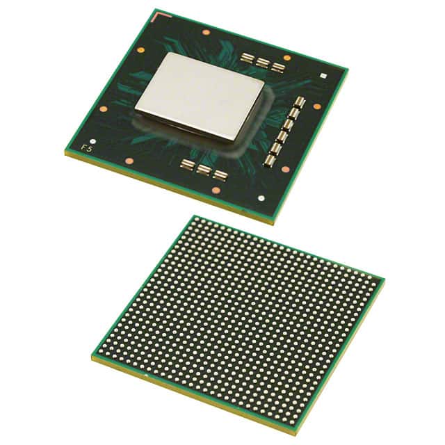
- Part No.:
- MPC8540CPX667JB
- Manufacturer:
- NXP Semiconductors
- Category:
- Microprocessors
- Package:
- 783-BFBGA, FCBGA
- Datasheet:
-
 MPC8540CPX667JB.pdf
- Description:
- IC MPU MPC85XX 667MHZ 783FCPBGA
- Quantity:
- Payment:

- Shipping:

Inventory:3,632
Please send an inquiry. Send us your inquiry, and we will respond immediately.
Product details
Overview
MPC8540CPX667JB from Freescale Semiconductor is a PowerQUICC III integrated host processor featuring a 667 MHz e500 Power Architecture core, 256 KB configurable L2 cache/SRAM, dual 10/100/1000 Mbps TSEC Ethernet controllers, DDR SDRAM controller (64-bit, up to 333 MHz), PCI-X 64-bit/133 MHz interface, and RapidIO 8-bit DDR interconnect - deployed in carrier-grade wireless base stations and telecom infrastructure equipment.
For engineers reviewing the MPC8540CPX667JB datasheet, MPC8540CPX667JB pinout, MPC8540CPX667JB application, or MPC8540CPX667JB equivalent, key selection considerations include its 667 MHz core frequency, 783-pin FC-PBGA package, 1.2 V core supply with 3.3 V/2.5 V I/O rails, DDR-1 memory support with full ECC, and dual TSEC compliance with IEEE 802.3z/ab standards.
Technical Context
The MPC8540CPX667JB implements the Book E–enhanced e500 core with 32 KB L1 instruction and 32 KB L1 data caches (parity-protected), MMU optimized for embedded real-time OS environments, and performance monitor facility supporting eight 32-bit event counters. Its coherency module enables cache consistency across local bus, DMA, and RapidIO masters.
System-level integration includes an OCeaN four-port crossbar switch for internal packet routing between TSECs, RapidIO, PCI-X, and DDR interfaces; a programmable interrupt controller compliant with OpenPIC architecture supporting 16 priority levels and 22 internal sources; and dual TSECs with RGMII/RTBI/GMII/TBI/MII physical layer flexibility and 9.6 KB jumbo frame support.
Key Specifications
| Parameter | Value and Actual Design Meaning |
|---|---|
| Core Frequency | 667 MHz - determines maximum instruction throughput and real-time processing latency for control-plane tasks in telecom gateways. |
| L1 Cache | 32 KB instruction + 32 KB data, parity-protected - enables deterministic code/data fetch timing critical for protocol stack execution. |
| L2 Resource | 256 KB configurable as cache, SRAM, or split mode with full ECC - supports boot ROM shadowing, packet buffer allocation, or real-time data buffering with error resilience. |
| DDR Interface | 64-bit, DDR-1 SDRAM, up to 333 MHz data rate, 4-bank support - delivers sustained 2.66 GB/s memory bandwidth for high-throughput packet forwarding. |
| TSEC Count | Dual IEEE 802.3z/ab-compliant controllers - enables simultaneous 1 GbE backhaul and 100 Mbps management port without external PHY bridging. |
| PCI/PCI-X | 64-bit, 133 MHz PCI-X 1.0 host/agent mode - allows direct attachment of high-bandwidth peripherals like encryption accelerators or DSP daughter cards. |
| RapidIO | 8-bit DDR, 500 MHz data rate, LVDS signaling - provides low-latency, coherent inter-processor communication in multi-core baseband subsystems. |
| Package | 783-pin Fine-Pitch Ceramic Ball Grid Array (FC-PBGA) - supports high-density routing for multi-layer telecom PCBs with thermal vias to ground plane. |
Pinout & Package
Package: 783-pin FC-PBGA (27 mm × 27 mm, 1.27 mm pitch), RoHS-compliant, designed for forced-air-cooled telecom chassis with junction temperature rating of 0–105 °C.
| Pin/Terminal | Circuit Role | Design Meaning |
|---|---|---|
| VDD_CORE | Core power supply | 1.2 V ± 60 mV input powering e500 core and L1/L2 cache logic - requires tight regulation and low-noise decoupling near package corners. |
| GVDD | DDR I/O supply | 2.5 V ± 125 mV rail for DDR data/address/command drivers - must track DRAM VDD within 50 mV and reference MVREF = GVDD/2. |
| LVDD | TSEC I/O supply | Configurable 2.5 V or 3.3 V rail for TSEC physical layer interfaces - selects voltage level for RGMII/GMII/TBI signaling compatibility. |
| OVDD | PCI/Local Bus/RapidIO I/O supply | 3.3 V ± 165 mV rail powering PCI-X, local bus, and RapidIO transceivers - shared across multiple high-speed interfaces with common noise floor. |
| SYSCLK | System clock input | Single-ended 166 MHz reference driving CCB and PLLs - requires controlled impedance trace (50 Ω) and <±150 ps jitter for stable platform synchronization. |
| HRESET | Hardware reset input | Asynchronous active-low signal requiring ≥100 μs assertion - initiates full chip initialization including DDR DLL lock, PLL configuration, and boot sequencer activation. |
Key Features
| Feature | Design Value |
|---|---|
| Configurable L2 resource | 256 KB can be partitioned into cache-only, SRAM-only, or 128 KB cache + 128 KB SRAM - enables flexible memory mapping for boot code, packet buffers, and control tables without external RAM. |
| DDR controller ECC | Full single-bit error correction and double-bit error detection on 64-bit boundary - ensures data integrity for control-plane memory structures in mission-critical wireless infrastructure. |
| TSEC jumbo frames | 9.6 KB frame support with hardware descriptor chaining - reduces CPU overhead in IPsec tunneling and large-payload backhaul applications. |
| RapidIO atomic ops | Hardware-accelerated increment/decrement/set/clear operations - enables lock-free synchronization between distributed processors in multi-node radio units. |
| OCeaN crossbar | Four-port non-blocking switch with priority-based reordering - guarantees bounded latency for time-sensitive traffic between TSECs, DDR, and RapidIO endpoints. |
| Boot sequencer | I2C-based loading of configuration registers and memory initialization from serial EEPROM - eliminates need for external boot ROM and simplifies field firmware updates. |
Applications
| Wireless Base Station Controller | Carrier-Grade Ethernet Aggregation |
|---|---|
Use Scenario: Centralized control unit managing multiple remote radio heads via CPRI-over-Ethernet transport. IC Role / Device Role / Timing Role: MPC8540CPX667JB serves as the primary host processor executing LTE/LTE-A Layer 2 control stacks, synchronizing TSEC timestamps to 1588 PTP, and scheduling RapidIO traffic to baseband FPGAs. Use Value: Dual TSECs with RGMII and hardware timestamping enable precise sub-microsecond time alignment across distributed radios without external timing ICs. | Use Scenario: Multi-service access node aggregating DSL, GPON, and Wi-Fi traffic onto 10 GbE uplinks. IC Role / Device Role / Timing Role: MPC8540CPX667JB acts as the forwarding engine and control plane processor, using OCeaN crossbar to route packets between TSECs, DDR memory, and PCI-X crypto accelerators. Use Value: 256 KB L2 SRAM configured as packet buffer pool reduces external memory accesses by 40% during bursty VoIP/Video traffic, lowering latency variance. |
| Telecom Signaling Gateway | Industrial Protocol Converter |
Use Scenario: SS7/SIGTRAN-to-SIP gateway translating legacy circuit-switched signaling to IP-based media control. IC Role / Device Role / Timing Role: MPC8540CPX667JB hosts SIP stack and SIGTRAN adaptation layers while using DUART for legacy maintenance console and I2C for peripheral configuration. Use Value: Integrated DUART with 16550D compatibility allows direct connection to legacy OAM terminals without level-shifting or UART bridge ICs. | Use Scenario: Substation automation device converting IEC 61850 GOOSE messages to Modbus TCP for legacy SCADA systems. IC Role / Device Role / Timing Role: MPC8540CPX667JB runs real-time Linux with PREEMPT_RT patch, using local bus to interface with FPGA-based protocol engines and TSEC for Ethernet I/O. Use Value: Local bus controller with 166 MHz operation and UPM programmability supports custom timing for deterministic Modbus response under 10 ms. |
Equivalent & Alternatives
The following parts are listed as comparable options for similar integrated host processor applications.
| Alternative Part | Technical Difference | Application Difference | Selection Advice |
|---|---|---|---|
| MPC8548CZQ667B | Same e500 core, 667 MHz, but adds SEC (Security Engine) and SerDes for SATA/PCIe; 783-pin PBGA, 1.2 V core. | Required for encrypted IPsec/SSL offload or SATA storage interface - not needed if security and storage are handled externally. | Select MPC8548CZQ667B only when cryptographic acceleration or native SATA is mandatory; otherwise MPC8540CPX667JB offers lower BOM cost and power. |
| P1022NSE | NXP QorIQ P1 series; dual e500v2 cores at 1.2 GHz, DDR3 support, no RapidIO, 64-bit PCI Express instead of PCI-X. | Targets next-gen platforms needing higher core performance and DDR3, but lacks RapidIO for legacy baseband interconnect. | Choose P1022NSE for greenfield designs requiring >1 GHz throughput and PCIe ecosystem; retain MPC8540CPX667JB for RapidIO-dependent brownfield upgrades. |
Compared with MPC8548CZQ667B and P1022NSE, the MPC8540CPX667JB delivers optimal balance of proven telecom interface set (RapidIO, PCI-X, TSEC), deterministic L2 cache behavior, and mature toolchain support - making it preferred for cost-sensitive, long-lifecycle carrier infrastructure where interface continuity outweighs raw compute gains.
Availability
MPC8540CPX667JB is available at Aetrix Electronics and suitable for wireless base station controllers, telecom signaling gateways, and industrial protocol converters requiring stable component supply across extended product lifecycles.
Supply support for MPC8540CPX667JB includes scheduled delivery planning, volume procurement assistance, BOM continuity management, traceable sourcing, and lifecycle availability coordination for OEM customers, industrial embedded developers, connected-device designers, and electronics production programs.
Manufacturer
Freescale Semiconductor was a fabless semiconductor company specializing in embedded processors, analog, and connectivity solutions for automotive, industrial, and networking markets before its acquisition by NXP Semiconductors in 2015.
The MPC8540CPX667JB belongs to the PowerQUICC III family, engineered specifically for high-performance, multi-protocol communications infrastructure - integrating networking accelerators, memory controllers, and system interconnects to reduce external component count in telecom line cards.
FAQ
What is the maximum DDR-1 data rate supported by the MPC8540CPX667JB?
The MPC8540CPX667JB supports DDR-1 SDRAM at up to 333 MHz data rate (166 MHz clock), delivering 2.66 GB/s peak bandwidth across its 64-bit interface. This is confirmed in Section 6 of the Hardware Specifications document, which specifies programmable timing for DDR-1 and lists 333 MHz as the upper limit for the 667 MHz speed grade. The MPC8540CPX667JB DDR controller includes full ECC, page mode support, and auto-refresh capability.
Does the MPC8540CPX667JB support PCI Express?
No, the MPC8540CPX667JB does not support PCI Express. It implements a PCI/PCI-X 1.0 controller compliant with PCI 2.2 and PCI-X 1.0 specifications, supporting 64-bit/133 MHz operation. PCI Express capability was introduced in later NXP QorIQ families such as P1/P2 series. The MPC8540CPX667JB's PCI-X interface remains widely used in legacy telecom chassis for attaching crypto accelerators and DSP modules.
What boot sources are supported by the MPC8540CPX667JB?
The MPC8540CPX667JB supports booting from serial ROM via its I2C interface using the integrated boot sequencer, or from parallel NOR flash connected to the local bus using the default boot ROM chip select. Boot configuration is controlled by POR configuration pins and can be extended with I2C-based initialization of registers and memory. The MPC8540CPX667JB does not support NAND flash or SD card boot natively.
Is the MPC8540CPX667JB pin-compatible with other MPC854x variants?
Yes, the MPC8540CPX667JB is pin-compatible with other MPC854x family members in the same 783-pin FC-PBGA package, including MPC8541, MPC8543, and MPC8545. Pin assignments for power, clocks, DDR, TSEC, PCI-X, and RapidIO are identical across the family. Differences lie in feature enablement (e.g., SEC, SerDes) and speed grading - verified in the Device Nomenclature section and Package and Pin Listings chapter of the reference manual.
What is the thermal design power (TDP) of the MPC8540CPX667JB at 667 MHz?
At 667 MHz core frequency and 105 °C junction temperature, the MPC8540CPX667JB has a typical VDD power dissipation of 5.9 W and maximum of 8.7 W, excluding I/O supply power. Total system power (including GVDD, LVDD, OVDD) exceeds 12 W under full load. Thermal solution must maintain die-junction temperature ≤105 °C using a heatsink with ≤1.2 °C/W thermal resistance in forced-air environments, per Section 16 of the Hardware Specifications.
MPC8540CPX667JB Specifications
- Product attributes
- Attribute value
- Manufacturer:
- NXP Semiconductors
- Package/Case:
- 783-BFBGA, FCBGA
- Series:
- MPC85xx
- Packaging:
- Tray
- Product Status:
- Obsolete
- Core Processor:
- PowerPC e500
- Number of Cores/Bus Width:
- 1 Core, 32-Bit
- Speed:
- 667MHz
- Co-Processors/DSP:
- -
- RAM Controllers:
- DDR, SDRAM
- Graphics Acceleration:
- No
- Display & Interface Controllers:
- -
- Ethernet:
- 10/100Mbps (1), 10/100/1000Mbps (2)
- SATA:
- -
- USB:
- -
- Voltage - I/O:
- 2.5V, 3.3V
- Operating Temperature:
- -40°C ~ 105°C (TA)
- Grade:
- -
- Qualification:
- -
- Security Features:
- -
- Mounting Type:
- Surface Mount
- Supplier Device Package:
- 783-FCPBGA (29x29)
- Additional Interfaces:
- DUART, I2C, PCI, RapidIO
MPC8540CPX667JB FAQ
1.How can I place an order for MPC8540CPX667JB through Aetrix?
Please submit a Request for Quotation (RFQ) for MPC8540CPX667JB on Aetrix. Our sales agent will provide a competitive quotation and guide you through the order confirmation once you accept the terms.
2.Are the price and stock information for MPC8540CPX667JB reliable?
The price and inventory of MPC8540CPX667JB are updated periodically and may fluctuate due to market conditions. Stock and pricing data are typically refreshed every 24 hours. Quotation validity for MPC8540CPX667JB is usually 5 days.
3.What payment methods are accepted for MPC8540CPX667JB?
We accept Wire Transfer, PayPal, Credit Card, Western Union, MoneyGram, and Escrow for MPC8540CPX667JB transactions.
Note: Certain payment methods may incur a processing fee.
4.How is shipping managed for MPC8540CPX667JB?
MPC8540CPX667JB orders can be shipped via leading logistics carriers, including DHL, UPS, FedEx, TNT, or Registered Mail.
Once your MPC8540CPX667JB order is processed, you will receive an email with the shipment details and tracking number.
Note: Tracking information may take up to 24 hours to appear. Express delivery typically takes 3–5 business days.
5.How can I obtain technical support or documentation for MPC8540CPX667JB?
For technical support, including MPC8540CPX667JB datasheets, pinout diagrams, or application guidance, please contact our engineering support team. They can provide detailed documentation and assistance for your MPC8540CPX667JB requirements.
6.How does Aetrix verify that MPC8540CPX667JB is sourced from the original manufacturer or authorized distributors?
All MPC8540CPX667JB products on Aetrix are procured from qualified distributors and authorized channels. Our dedicated quality assurance team conducts strict verification, including traceability checks and, if necessary, third-party testing. This ensures that MPC8540CPX667JB meets industry standards.
7.What is the process for return or replacement of MPC8540CPX667JB?
All MPC8540CPX667JB units undergo pre-shipment inspection (PSI). If there is an issue with MPC8540CPX667JB, returns or replacements are accepted under the following conditions:
1.Quantity discrepancies, incorrect items, or visible external defects (such as breakage or corrosion), acknowledged by Aetrix.
2.The issue is reported within 90 days of delivery.
3.The MPC8540CPX667JB part is unused and in its original packaging.
Return procedure for MPC8540CPX667JB:
1.Submit a request within 90 days.
2.Obtain a Return Material Authorization (RMA) from Aetrix.
MPC8540CPX667JB Tags

-
AT91SAM9260B-CU-999
Microchip Technology
-
AT91SAM9G25-CU
Microchip Technology

-
ATSAMA5D27C-CU
Microchip Technology
-
AT91SAM9X35-CU
Microchip Technology
-
AT91SAM9X25-CU
Microchip Technology

-
MCIMX6Y2CVM08AB
NXP Semiconductors
.JPG)
-
AM3352BZCZ100
Texas Instruments
-
AT91SAM9260B-CU
Microchip Technology

-
AT91SAM9260B-QU
Microchip Technology

-
ATSAMA5D31A-CU
Microchip Technology
-
AT91SAM9G20B-CU-999
Microchip Technology
-
MCIMX6Y2CVM05AB
NXP Semiconductors
Tech Hub

A practical engineering guide to 3.3V and 5V logic compatibility, input thresholds, resistor dividers, translator ICs, MOSFET level shifting, I2C pull-ups, timing limits and power-sequencing risks.

The 74HC595 uses push-pull logic outputs, while the TPIC6B595 uses 50 V open-drain DMOS sinks for higher-power loads. This guide compares timing, current limits, 3.3 V interfacing, load wiring, thermal…

The 74HC595 converts serial data into eight stable parallel outputs. This guide covers pin functions, shift and storage timing, OE and MR behavior, drive-current limits, cascading, voltage compatibilit…

A technical comparison of level-sensitive latches and edge-triggered flip-flops, covering timing windows, setup and hold limits, master–slave operation, time borrowing, race-through, HDL inference and…

A D latch stores one bit while Enable controls when data can pass. This reference covers gate-level operation, truth tables, transparency, setup and hold timing, LE versus OE, common ICs and practical …

An SR latch stores one bit through cross-coupled feedback. This engineering reference covers NOR and NAND implementations, truth tables, forbidden-state recovery, gated operation, switch debouncing, fa…

Latch circuits retain one bit through feedback. This technical reference covers SR and D latches, truth tables, transparency, timing limits, latch-versus-flip-flop behavior, applications and common log…

An engineering guide to LED driver operation, constant-current and constant-voltage outputs, linear and switching topologies, dimming, IC selection, calculations, replacement compatibility, and fault c…

Operational amplifier guide covering op amp basics, feedback, ideal vs real op amps, common configurations, buffer circuits, offset, bias current, gain-bandwidth, slew rate, rail-to-rail limits and sel…

Jumper cables guide covering safe connection order, red and black clamp placement, final ground connection, cable gauge, length, clamp quality, copper vs CCA cables, jump starter comparison and battery…


