
 My Inquiry
 My Account


NXP Semiconductors MPC8540CVT667JB
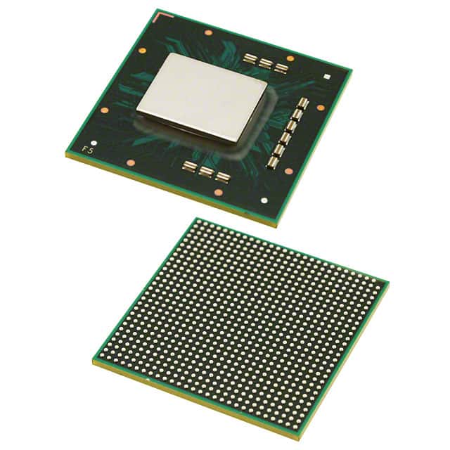
- Part No.:
- MPC8540CVT667JB
- Manufacturer:
- NXP Semiconductors
- Category:
- Microprocessors
- Package:
- 783-BFBGA, FCBGA
- Datasheet:
-
 MPC8540CVT667JB.pdf
- Description:
- IC MPU MPC85XX 667MHZ 783FCPBGA
- Quantity:
- Payment:

- Shipping:

Inventory:3,422
Please send an inquiry. Send us your inquiry, and we will respond immediately.
Product details
Overview
MPC8540CVT667JB from NXP (formerly Freescale) is a PowerQUICC™ III integrated host processor featuring a 32-bit e500 Power Architecture™ core, 256 KB configurable L2 cache/SRAM, dual 10/100/1000 Mbps TSEC Ethernet controllers, DDR SDRAM controller (64-bit, up to 333 MHz), PCI/PCI-X (64-bit, 133 MHz), RapidIO (8-bit, 500 MHz), and OCeaN packet switch - deployed in telecom infrastructure line cards and wireless baseband units.
For engineers reviewing the MPC8540CVT667JB datasheet, MPC8540CVT667JB pinout, MPC8540CVT667JB application, or MPC8540CVT667JB equivalent, key selection criteria include its 667 MHz e500 core frequency, 783-pin FC-PBGA package with 2.5 V DDR I/O and 3.3 V system I/O, support for ECC-protected memory subsystems, and multi-protocol connectivity for carrier-grade control plane processing.
Technical Context
The MPC8540CVT667JB implements the Book E–enhanced e500 core with 32 KB L1 instruction and 32 KB L1 data caches (parity-protected), MMU optimized for embedded real-time OS environments, and performance monitor facility with eight 32-bit event counters. Its coherency module enables cache snooping across local bus, PCI, and RapidIO masters.
System-level integration includes an ATMU with eight local access windows and configurable inbound/outbound translations for PCI/PCI-X and RapidIO, a DDR controller supporting registered DIMMs and auto-refresh, and dual TSECs compliant with IEEE 802.3z (Gigabit), 802.3ab (1000BASE-T), and RGMII/RTBI physical interfaces - all operating under a fully static 1.2 V core supply with 2.5 V/3.3 V I/O domains.
Key Specifications
| Parameter | Value and Actual Design Meaning |
|---|---|
| e500 Core Frequency | 667 MHz - delivers deterministic real-time execution for control-plane firmware in telecom gateways and media processors. |
| L2 Cache/SRAM | 256 KB configurable - supports full cache, full SRAM, or split 128 KB cache + 128 KB SRAM modes with full ECC on 64-bit boundaries. |
| DDR Interface | 64-bit, 333 MHz data rate - enables up to 2.66 GB/s bandwidth to DDR-1 SDRAM with page mode, auto-refresh, and CKE-based power management. |
| TSEC Ethernet | Dual 10/100/1000 Mbps - each supports GMII, MII, TBI, RGMII, RTBI, and IEEE 802.3x flow control with 9.6 KB jumbo frames and RMON statistics. |
| PCI/PCI-X Support | 64-bit, 133 MHz PCI-X - operates in host or agent mode with DAC, split transactions, and hardware-enforced coherency for bridging legacy peripherals. |
| RapidIO Interface | 8-bit, 500 MHz DDR LVDS - provides packet-switched interconnect with CRC protection, atomic operations, and four priority levels for chip-to-chip communication. |
| Package | 783-pin FC-PBGA (35 mm × 35 mm, 1.0 mm pitch) - requires controlled-impedance PCB layout with dedicated VDD, AVDD, GVDD, LVDD, and OVDD power planes. |
Pinout & Package
Package: 783-pin Fine-Pitch Ceramic Ball Grid Array (FC-PBGA), 35 mm × 35 mm, 1.0 mm ball pitch, RoHS-compliant. Thermal pad on underside requires solder paste stencil opening and thermal via array per Freescale AN2812.
| Pin/Terminal | Circuit Role | Design Meaning |
|---|---|---|
| VDD[0:15] | Core Power Supply | 16 dedicated 1.2 V inputs for e500 core and L2 cache - must be decoupled with ≥10 µF bulk + 10× 0.1 µF ceramic per group near package edge. |
| AVDD[0:1] | PLL Power Supply | Two 1.2 V supplies for platform/system PLLs - require ultra-low-noise regulation and separate filtering from VDD. |
| GVDD[0:7] | DDR I/O Supply | Eight 2.5 V SSTL2-compatible pins - reference MVREF must be set to GVDD/2 ±2% with ≤100 µA leakage for stable DDR timing. |
| LVDD[0:3] | TSEC I/O Supply | Four 2.5 V or 3.3 V supplies - selectable per PHY interface (RGMII at 2.5 V, GMII at 3.3 V); mismatch causes signal integrity failure. |
| OVDD[0:19] | System I/O Supply | 20 pins for 3.3 V logic (PCI, Local Bus, JTAG, I²C, DUART) - shared rail requires sequencing after VDD and before GVDD/LVDD per power-up order. |
| HRESET_B | Hard Reset Input | Active-low asynchronous reset - must be held low ≥100 µs after power stabilization; releases internal state machines and initiates boot sequencer. |
Key Features
| Feature | Design Value |
|---|---|
| Configurable L2 Memory | 256 KB reconfigurable as cache, SRAM, or hybrid - enables deterministic latency-critical code/data placement without external memory arbitration. |
| ECC Protection | Full ECC on L2 cache and DDR interface - corrects single-bit errors and detects double-bit errors in both instruction and data paths for carrier-grade reliability. |
| OCeaN Packet Switch | Four-port crossbar with priority-based reordering - eliminates bus contention between TSEC, RapidIO, PCI, and local bus masters in multi-protocol systems. |
| Boot Sequencer | I²C-based serial ROM loader with CRC-verified preamble - enables secure, fail-safe initialization of configuration registers and memory-mapped peripherals at power-on. |
| Power Management | Doze/nap/sleep modes with dynamic block gating - reduces active power by >40% during idle periods while preserving context in L1/L2 caches. |
Applications
| Wireless Baseband Processing | Carrier-Grade Router Control Plane |
|---|---|
Use Scenario: Real-time processing of LTE/LTE-A control signaling and layer-2 protocol stacks in macrocell baseband units. IC Role / Device Role / Timing Role: Primary host processor executing Linux BSP with deterministic interrupt latency for RRC, PDCP, and MAC layer scheduling. Use Value: Dual TSECs handle backhaul traffic while RapidIO links to DSP/FPGA accelerators; 256 KB L2 cache ensures sub-100 ns instruction fetch for time-critical tasks. |
Use Scenario: Control plane management in 10 Gbps carrier routers, handling BGP/OSPF routing tables, CLI, and SNMP agents. IC Role / Device Role / Timing Role: Central control processor interfacing to line cards via PCI-X and to management modules via I²C/DUART. Use Value: ATMU enables seamless mapping of 4 GB of DDR memory and 2 GB of flash; OCeaN switch prevents congestion between TSEC and PCI-X traffic streams. |
| Telecom Media Gateway | Industrial Protocol Gateway |
Use Scenario: Voice-over-IP media gateway converting TDM (E1/T1) to SIP/RTP streams in PSTN edge nodes. IC Role / Device Role / Timing Role: Integrated host processor managing voice codec offload, packet classification, and QoS policing. Use Value: DDR controller supports 1 GB DDR-1 with ECC for large jitter buffers; dual TSECs isolate voice and signaling traffic onto separate VLANs. |
Use Scenario: Fieldbus-to-Ethernet gateway consolidating Modbus TCP, PROFINET, and EtherCAT in factory automation PLCs. IC Role / Device Role / Timing Role: Deterministic real-time processor running RTOS with precise timer interrupts for cyclic I/O scanning. Use Value: Programmable interrupt controller (OpenPIC-compliant) supports 16 priority levels and 22 internal sources - enabling strict deadline enforcement for motion control loops. |
Equivalent & Alternatives
The following parts are listed as comparable options for similar integrated host processor applications.
| Alternative Part | Technical Difference | Application Difference | Selection Advice |
|---|---|---|---|
| MPC8548CZQ667B | Same e500 core, 667 MHz, but adds SEC (Security Engine) and enhanced DDR2 support; 783-pin PBGA, identical footprint. | Required where IPsec/SSL acceleration or DDR2 memory compatibility is mandatory - not drop-in for DDR-1-only designs. | Select MPC8548CZQ667B only if cryptographic offload or DDR2 migration path is needed; otherwise MPC8540CVT667JB offers lower BOM cost and simpler power design. |
| P1022NSEALF | Power Architecture e500v2 core at 1.2 GHz, dual 1 GbE, PCIe v1.1, no RapidIO; 689-pin PBGA - smaller footprint, different pinout. | Suitable for newer designs targeting higher throughput and PCIe ecosystem, but lacks RapidIO and OCeaN switch - requires board redesign. | Choose P1022NSEALF for greenfield projects needing PCIe and higher clock speed; MPC8540CVT667JB remains optimal for legacy RapidIO-based infrastructure upgrades. |
Compared with MPC8548CZQ667B, MPC8540CVT667JB omits security acceleration but simplifies power delivery and DDR-1 timing closure; versus P1022NSEALF, it retains RapidIO and OCeaN for existing telecom interconnect architectures but trades peak performance for proven field reliability in deployed systems.
Availability
MPC8540CVT667JB is available at Aetrix Electronics and suitable for telecom infrastructure, wireless baseband units, and industrial protocol gateways requiring stable component supply and long-term lifecycle support.
Supply support for MPC8540CVT667JB includes scheduled delivery planning, volume procurement assistance, BOM continuity management, traceable sourcing, and lifecycle availability coordination for OEM customers, industrial embedded developers, connected-device designers, and electronics production programs.
Manufacturer
NXP Semiconductors is a global semiconductor leader focused on secure connectivity solutions for automotive, industrial, and networking markets, with roots in Freescale's Power Architecture heritage.
The MPC8540CVT667JB belongs to the PowerQUICC™ III family - designed specifically for high-reliability control-plane processing in carrier-class networking and telecommunications equipment where multi-protocol integration and ECC-protected memory are critical.
FAQ
What is the maximum DDR-1 data rate supported by the MPC8540CVT667JB?
The MPC8540CVT667JB supports a DDR-1 data rate of up to 333 MHz, delivering 2.66 GB/s peak bandwidth across its 64-bit interface. This is confirmed in Section 6 of the Hardware Specifications document, which specifies programmable timing for DDR-1 SDRAM with four banks, registered DIMM support, and full ECC protection - all validated for operation at 333 MHz with 2.5 V SSTL2 I/O.
Does the MPC8540CVT667JB support PCIe or only PCI/PCI-X?
The MPC8540CVT667JB supports PCI 2.2 and PCI-X 1.0 (up to 133 MHz, 64-bit), but does not implement PCIe. Section 12 of the Hardware Specifications explicitly states PCI/PCI-X compliance only, with features including dual address cycles, split transactions, and 64-bit streaming - no mention of PCIe endpoints, root complexes, or PCIe-specific registers appears in the documentation for MPC8540CVT667JB.
What boot sources are supported by the MPC8540CVT667JB?
The MPC8540CVT667JB supports booting from serial ROM via its I²C interface using the integrated boot sequencer, as detailed in Section 1.1 (Boot Sequencer) of the Hardware Specifications. It also supports parallel boot from local bus ROM (8-/16-/32-bit width) using the default chip select, but does not support NAND/NOR flash boot directly - external glue logic or FPGA bridging is required for those interfaces.
Is the MPC8540CVT667JB pin-compatible with other MPC854x variants like MPC8547 or MPC8548?
No, the MPC8540CVT667JB is not pin-compatible with MPC8547 or MPC8548. While all share the 783-pin FC-PBGA package, Freescale's Device Nomenclature section (Section 19) and pin listings (Section 14) confirm functional pin assignments differ significantly - especially for RapidIO, SEC, and DDR2 signals introduced in later variants. Board-level replacement requires schematic and layout revision.
What is the junction temperature limit for continuous operation of the MPC8540CVT667JB?
The MPC8540CVT667JB has a maximum die-junction temperature (Tj) of 105°C for continuous operation, as specified in Table 2 (Recommended Operating Conditions) of the Hardware Specifications. This limit assumes proper thermal management: 783-pin FC-PBGA mounting with thermal vias, ≥2 oz copper planes, and airflow ≥200 LFM - exceeding 105°C risks permanent parametric shift or latch-up.
MPC8540CVT667JB Specifications
- Product attributes
- Attribute value
- Manufacturer:
- NXP Semiconductors
- Package/Case:
- 783-BFBGA, FCBGA
- Series:
- MPC85xx
- Packaging:
- Tray
- Product Status:
- Obsolete
- Core Processor:
- PowerPC e500
- Number of Cores/Bus Width:
- 1 Core, 32-Bit
- Speed:
- 667MHz
- Co-Processors/DSP:
- -
- RAM Controllers:
- DDR, SDRAM
- Graphics Acceleration:
- No
- Display & Interface Controllers:
- -
- Ethernet:
- 10/100Mbps (1), 10/100/1000Mbps (2)
- SATA:
- -
- USB:
- -
- Voltage - I/O:
- 2.5V, 3.3V
- Operating Temperature:
- -40°C ~ 105°C (TA)
- Grade:
- -
- Qualification:
- -
- Security Features:
- -
- Mounting Type:
- Surface Mount
- Supplier Device Package:
- 783-FCPBGA (29x29)
- Additional Interfaces:
- DUART, I2C, PCI, RapidIO
MPC8540CVT667JB FAQ
1.How can I place an order for MPC8540CVT667JB through Aetrix?
Please submit a Request for Quotation (RFQ) for MPC8540CVT667JB on Aetrix. Our sales agent will provide a competitive quotation and guide you through the order confirmation once you accept the terms.
2.Are the price and stock information for MPC8540CVT667JB reliable?
The price and inventory of MPC8540CVT667JB are updated periodically and may fluctuate due to market conditions. Stock and pricing data are typically refreshed every 24 hours. Quotation validity for MPC8540CVT667JB is usually 5 days.
3.What payment methods are accepted for MPC8540CVT667JB?
We accept Wire Transfer, PayPal, Credit Card, Western Union, MoneyGram, and Escrow for MPC8540CVT667JB transactions.
Note: Certain payment methods may incur a processing fee.
4.How is shipping managed for MPC8540CVT667JB?
MPC8540CVT667JB orders can be shipped via leading logistics carriers, including DHL, UPS, FedEx, TNT, or Registered Mail.
Once your MPC8540CVT667JB order is processed, you will receive an email with the shipment details and tracking number.
Note: Tracking information may take up to 24 hours to appear. Express delivery typically takes 3–5 business days.
5.How can I obtain technical support or documentation for MPC8540CVT667JB?
For technical support, including MPC8540CVT667JB datasheets, pinout diagrams, or application guidance, please contact our engineering support team. They can provide detailed documentation and assistance for your MPC8540CVT667JB requirements.
6.How does Aetrix verify that MPC8540CVT667JB is sourced from the original manufacturer or authorized distributors?
All MPC8540CVT667JB products on Aetrix are procured from qualified distributors and authorized channels. Our dedicated quality assurance team conducts strict verification, including traceability checks and, if necessary, third-party testing. This ensures that MPC8540CVT667JB meets industry standards.
7.What is the process for return or replacement of MPC8540CVT667JB?
All MPC8540CVT667JB units undergo pre-shipment inspection (PSI). If there is an issue with MPC8540CVT667JB, returns or replacements are accepted under the following conditions:
1.Quantity discrepancies, incorrect items, or visible external defects (such as breakage or corrosion), acknowledged by Aetrix.
2.The issue is reported within 90 days of delivery.
3.The MPC8540CVT667JB part is unused and in its original packaging.
Return procedure for MPC8540CVT667JB:
1.Submit a request within 90 days.
2.Obtain a Return Material Authorization (RMA) from Aetrix.
MPC8540CVT667JB Tags

-
AT91SAM9260B-CU-999
Microchip Technology
-
AT91SAM9G25-CU
Microchip Technology

-
ATSAMA5D27C-CU
Microchip Technology
-
AT91SAM9X35-CU
Microchip Technology
-
AT91SAM9X25-CU
Microchip Technology

-
MCIMX6Y2CVM08AB
NXP Semiconductors
.JPG)
-
AM3352BZCZ100
Texas Instruments
-
AT91SAM9260B-CU
Microchip Technology

-
AT91SAM9260B-QU
Microchip Technology

-
ATSAMA5D31A-CU
Microchip Technology
-
AT91SAM9G20B-CU-999
Microchip Technology
-
MCIMX6Y2CVM05AB
NXP Semiconductors
Tech Hub

A practical engineering guide to 3.3V and 5V logic compatibility, input thresholds, resistor dividers, translator ICs, MOSFET level shifting, I2C pull-ups, timing limits and power-sequencing risks.

The 74HC595 uses push-pull logic outputs, while the TPIC6B595 uses 50 V open-drain DMOS sinks for higher-power loads. This guide compares timing, current limits, 3.3 V interfacing, load wiring, thermal…

The 74HC595 converts serial data into eight stable parallel outputs. This guide covers pin functions, shift and storage timing, OE and MR behavior, drive-current limits, cascading, voltage compatibilit…

A technical comparison of level-sensitive latches and edge-triggered flip-flops, covering timing windows, setup and hold limits, master–slave operation, time borrowing, race-through, HDL inference and…

A D latch stores one bit while Enable controls when data can pass. This reference covers gate-level operation, truth tables, transparency, setup and hold timing, LE versus OE, common ICs and practical …

An SR latch stores one bit through cross-coupled feedback. This engineering reference covers NOR and NAND implementations, truth tables, forbidden-state recovery, gated operation, switch debouncing, fa…

Latch circuits retain one bit through feedback. This technical reference covers SR and D latches, truth tables, transparency, timing limits, latch-versus-flip-flop behavior, applications and common log…

An engineering guide to LED driver operation, constant-current and constant-voltage outputs, linear and switching topologies, dimming, IC selection, calculations, replacement compatibility, and fault c…

Operational amplifier guide covering op amp basics, feedback, ideal vs real op amps, common configurations, buffer circuits, offset, bias current, gain-bandwidth, slew rate, rail-to-rail limits and sel…

Jumper cables guide covering safe connection order, red and black clamp placement, final ground connection, cable gauge, length, clamp quality, copper vs CCA cables, jump starter comparison and battery…


