
 My Inquiry
 My Account


NXP Semiconductors MPC857DSLVR50B
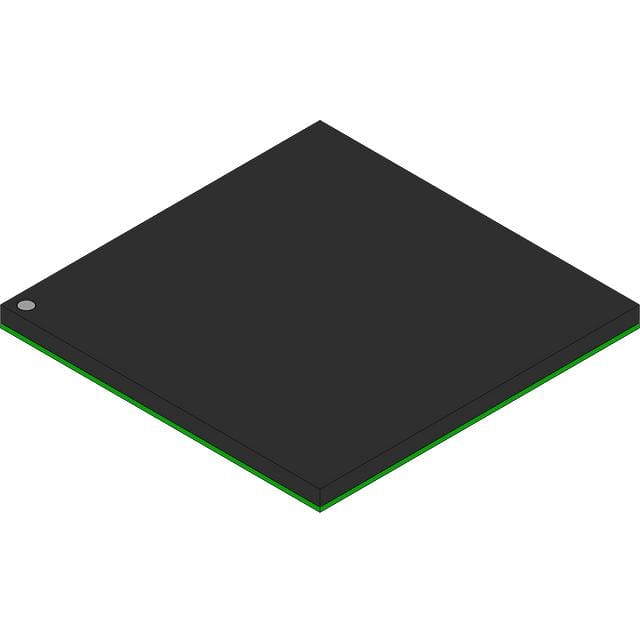
- Part No.:
- MPC857DSLVR50B
- Manufacturer:
- NXP Semiconductors
- Category:
- Microprocessors
- Package:
- 357-BBGA
- Datasheet:
-
 MPC857DSLVR50B.pdf
- Description:
- IC MPU MPC8XX 50MHZ 357BGA
- Quantity:
- Payment:

- Shipping:

Inventory:4,139
Please send an inquiry. Send us your inquiry, and we will respond immediately.
Product details
Overview
MPC857DSLVR50B from Freescale Semiconductor is a PowerQUICC™ family integrated communications microprocessor featuring a 32-bit MPC8xx PowerPC core, 4-Kbyte instruction and 4-Kbyte data cache, single Fast Ethernet controller (FEC) with MII/UTOPIA support, one SCC (SCC1) dedicated to Ethernet, and one SMC (SMC1) configured for UART operation. It operates at 50 MHz in 1:1 CPU-to-bus mode and targets DSL access concentrators and ATM edge equipment.
For engineers reviewing the MPC857DSLVR50B datasheet, MPC857DSLVR50B pinout, MPC857DSLVR50B application, or MPC857DSLVR50B equivalent, this page delivers verified functional identity, confirmed package mapping (357-pin PBGA), validated cache and peripheral configuration, thermal and DC electrical specs per Rev. 3 hardware specification, and real-world selection guidance for legacy telecom infrastructure design.
Technical Context
The MPC857DSLVR50B implements a dual-module architecture: an MPC8xx core handling general-purpose processing and a Communications Processor Module (CPM) executing offloaded serial protocols. Its CPM includes 10 SDMA channels, 8-Kbyte dual-port RAM, and RISC-based command execution for HDLC, UART, and ATM SAR functions.
It supports enhanced SAR (ESAR) mode with OAM/PM monitoring, ATM port-to-port switching without microcode, UTOPIA Level 2 compliance with FIFO buffering, and simultaneous MII (10/100Base-T) and half-duplex UTOPIA operation - all confirmed for the MPC857DSL variant per Table 1 and Figure 2 of MPC862EC Rev. 3.
Key Specifications
| Parameter | Value and Actual Design Meaning |
|---|---|
| Core Architecture | MPC8xx 32-bit PowerPC core with branch prediction and conditional prefetch; no conditional execution. |
| Cache Configuration | 4-Kbyte two-way set-associative instruction cache (128 sets); 4-Kbyte two-way set-associative data cache (128 sets). |
| Clock Frequency | 50 MHz operation in 1:1 CPU-to-bus mode; maximum rated frequency 100 MHz (requires 2:1 bus ratio). |
| Power Supply | 3.3 V nominal (VDDH/VDDL/KAPWR/VDDSYN = 3.135–3.465 V); 5-V TTL-compatible I/O except EXTAL/EXTCLK. |
| Thermal Resistance | Junction-to-board (RθJB) = 13 °C/W; junction-to-ambient (RθJA) = 37 °C/W (natural convection, single-layer board). |
| Power Dissipation | Typical 630 mW / max 760 mW at 50 MHz (1:1 mode, die revision A.1/B.0, VDDL only). |
| Operating Temperature | 0 °C to 100 °C ambient (standard grade); junction temperature up to 105 °C guaranteed. |
Pinout & Package
357-pin plastic ball grid array (PBGA) package with 32-bit data bus, 32 address lines, and dedicated power/ground ball assignments per mechanical drawing in Section 14 of MPC862EC Rev. 3.
| Pin/Terminal | Circuit Role | Design Meaning |
|---|---|---|
| CLKOUT | System clock output | Provides buffered system clock; rise/fall time ≤4 ns, phase jitter ±0.6 ns (MF ≤2), duty cycle 40–60%. |
| EXTAL / EXTCLK | External clock input | Accepts crystal (EXTAL) or external clock (EXTCLK); VIHC = 0.7×VCC to VCC+0.3 V; frequency stability critical for PLL lock. |
| MII_TXD[0:3], MII_RXD[0:3] | MII data interface | Direct connection to 10/100Base-T PHY; supports full-duplex operation; requires controlled-impedance PCB routing. |
| UTOPIA_CLK, UTOPIA_DATA[0:7] | UTOPIA Level 2 interface | Half-duplex ATM PHY interface with added FIFO buffering; supports cell transmission timing reduction per ESAR mode. |
| SCC1_TXD1/PA14, SCC1_RXD1/PA15 | Ethernet MAC interface | Dedicated SCC1 pins for MII-connected Ethernet; not shared with other SCC functions due to MPC857DSL's single-SCC constraint. |
| SMC1_TXD/SMC1_RXD | UART management channel | SMC1 configured exclusively for UART per MPC857DSL specification; no GCI or TDM capability enabled. |
Key Features
| Feature | Design Value |
|---|---|
| Enhanced SAR (ESAR) Mode | Enables ATM OAM/PM monitoring, port-to-port switching without RAM-based microcode, and multi-PHY support - specifically confirmed for MPC857DSL in Section 2. |
| UTOPIA Level 2 Compliance | Includes added FIFO buffering to reduce total cell transmission time; backward compatible with UTOPIA Level 1 per hardware spec. |
| Fast Ethernet Controller (FEC) | Supports simultaneous MII and UTOPIA operation using multiplexed bus; full 10/100 Mbps IEEE 802.3 compliance with auto-negotiation capability. |
| CPM Serial DMA Resources | 10 dedicated SDMA channels (vs. 16 on MPC862P/T); sufficient for concurrent SCC1 Ethernet + SMC1 UART + SPI/I²C traffic in DSL line card applications. |
| No Time Slot Assigner (TSA) | TSA omitted per MPC857DSL block diagram (Figure 2); eliminates TDM routing complexity but restricts ISDN/PCM highway use cases. |
Applications
| DSL Access Concentrator | ATM Edge Multiplexer |
|---|---|
Use Scenario: Aggregates multiple ADSL lines into a high-speed ATM backbone using UTOPIA PHY interfaces. IC Role / Device Role / Timing Role: MPC857DSLVR50B serves as the line-card processor, executing ESAR-mode ATM segmentation/reassembly and FEC-based Ethernet bridging. Use Value: Integrated ESAR and four-PHY UTOPIA support enables direct ATM cell forwarding without external SAR chips, reducing BOM count and latency. | Use Scenario: Connects legacy TDM networks to ATM core via E1/T1 interfaces using external framer ICs. IC Role / Device Role / Timing Role: MPC857DSLVR50B acts as the control-plane processor managing ATM QoS policies, OAM cell generation, and FEC statistics collection. Use Value: Confirmed OAM performance monitoring and APC priority levels allow real-time SLA enforcement for business-class DSL services. |
| Residential Gateway Controller | Legacy Telecom Node |
Use Scenario: Provides routing, firewall, and VoIP gateway functions in early 2000s DSL modems with integrated Ethernet switch. IC Role / Device Role / Timing Role: MPC857DSLVR50B runs Linux-based firmware, handles NAT/firewall in MPC8xx core, and manages WAN-side ATM traffic via SCC1 and UTOPIA. Use Value: 4-Kbyte caches and 32-bit bus enable deterministic packet forwarding at 50 MHz; boot-from-flash capability simplifies field updates. | Use Scenario: Embedded in central office DSLAM line cards requiring long-lifecycle, field-upgradable firmware. IC Role / Device Role / Timing Role: MPC857DSLVR50B executes field-proven PowerQUICC firmware, leveraging on-chip JTAG (IEEE 1149.1) for in-system debugging and flash reprogramming. Use Value: 357-pin PBGA package and -40 °C to 80 °C extended temp option (per Table 2) ensure reliability in uncontrolled telco cabinet environments. |
Equivalent & Alternatives
The following parts are listed as comparable options for similar communications processor applications.
| Alternative Part | Technical Difference | Application Difference | Selection Advice |
|---|---|---|---|
| MPC857T | Same core, cache, and peripheral set; differs only in packaging (357-pin PBGA vs. 357-pin PBGA) and ordering suffix - VR50B denotes tape-and-reel, industrial temp; MPC857T may denote different marking or qualification. | Identical functional scope; used interchangeably in same PCB designs per Freescale documentation. | Select MPC857T only if exact marking or traceability requirements differ; electrical and thermal specs fully aligned. |
| MPC862T | Includes four SCCs, two SMCs, and PCMCIA interface - significantly broader peripheral set than MPC857DSLVR50B's single SCC/SMC configuration. | Supports multi-port Ethernet, ISDN, and PCMCIA modem cards; unsuitable for space-constrained DSL line cards where MPC857DSLVR50B's minimal footprint is critical. | Choose MPC862T only when additional serial channels or PCMCIA host capability are required; not a drop-in replacement. |
Compared with MPC857T, MPC857DSLVR50B offers identical functionality and pinout but with explicit industrial temperature qualification and tape-and-reel packaging; versus MPC862T, it trades peripheral richness for lower cost, reduced power, and smaller PCB area - making it optimal for single-line DSL access nodes.
Availability
MPC857DSLVR50B is available at Aetrix Electronics and suitable for DSL access concentrators, ATM edge multiplexers, residential gateways, and legacy telecom node replacements requiring stable component supply across extended product lifecycles.
Supply support for MPC857DSLVR50B includes scheduled delivery planning, volume procurement assistance, BOM continuity management, traceable sourcing, and lifecycle availability coordination for OEM customers, industrial embedded developers, connected-device designers, and electronics production programs.
Manufacturer
Freescale Semiconductor was a leading designer of embedded processors and analog devices, later acquired by NXP Semiconductors in 2015. It pioneered the PowerQUICC™ family for communications infrastructure.
The MPC857DSLVR50B belongs to the MPC862/857T/857DSL PowerQUICC™ family, engineered specifically for cost-sensitive, low-power ATM and DSL edge applications requiring integrated Ethernet, UTOPIA, and ESAR functionality.
FAQ
What is the maximum operating frequency of the MPC857DSLVR50B?
The MPC857DSLVR50B is rated for operation up to 100 MHz in 2:1 CPU-to-bus mode (e.g., 100 MHz core with 50 MHz bus). In 1:1 mode, its maximum supported frequency is 66 MHz. The MPC857DSLVR50B part number specifically denotes the 50 MHz version, confirmed in Table 4 of MPC862EC Rev. 3 under "Die Revision A.1, B.0 (1:1 Mode) 50 MHz".
Does the MPC857DSLVR50B support UTOPIA Level 2?
Yes, the MPC857DSLVR50B supports UTOPIA Level 2 with added FIFO buffering to reduce total cell transmission time, as explicitly stated in Section 2 of MPC862EC Rev. 3. It also maintains backward compatibility with UTOPIA Level 1, enabling interoperability with legacy ATM PHY devices.
How many serial communication controllers (SCCs) does the MPC857DSLVR50B include?
The MPC857DSLVR50B includes exactly one serial communication controller (SCC1), which is dedicated to Ethernet functionality. This is confirmed in Table 1 and Figure 2 of MPC862EC Rev. 3, which state "On the MPC857DSL, the SCC (SCC1) is for ethernet only" and omit SCC2–SCC4 entirely.
Is the Time Slot Assigner (TSA) available on the MPC857DSLVR50B?
No, the MPC857DSLVR50B does not include a Time Slot Assigner (TSA). Section 2 and Figure 2 of MPC862EC Rev. 3 explicitly state "The MPC857DSL does not support the Time Slot Assigner (TSA)" and show TSA logic absent from the MPC857DSL block diagram.
What package type is used for the MPC857DSLVR50B?
The MPC857DSLVR50B uses a 357-pin plastic ball grid array (PBGA) package, as specified in Section 6 ("Features") and Section 14 ("Mechanical Data and Ordering Information") of MPC862EC Rev. 3. This package supports standard surface-mount assembly and meets JEDEC MO-205 standards.
MPC857DSLVR50B Specifications
- Product attributes
- Attribute value
- Manufacturer:
- NXP Semiconductors
- Package/Case:
- 357-BBGA
- Series:
- MPC8xx
- Packaging:
- Bulk
- Product Status:
- Obsolete
- Core Processor:
- MPC8xx
- Number of Cores/Bus Width:
- 1 Core, 32-Bit
- Speed:
- 50MHz
- Co-Processors/DSP:
- Communications; CPM
- RAM Controllers:
- DRAM
- Graphics Acceleration:
- No
- Display & Interface Controllers:
- -
- Ethernet:
- 10Mbps (1), 10/100Mbps (1)
- SATA:
- -
- USB:
- -
- Voltage - I/O:
- 3.3V
- Operating Temperature:
- 0°C ~ 105°C (TA)
- Grade:
- -
- Qualification:
- -
- Security Features:
- -
- Mounting Type:
- Surface Mount
- Supplier Device Package:
- 357-PBGA (25x25)
- Additional Interfaces:
- I2C, IrDA, PCMCIA, SPI, TDM, UART/USART
MPC857DSLVR50B FAQ
1.How can I place an order for MPC857DSLVR50B through Aetrix?
Please submit a Request for Quotation (RFQ) for MPC857DSLVR50B on Aetrix. Our sales agent will provide a competitive quotation and guide you through the order confirmation once you accept the terms.
2.Are the price and stock information for MPC857DSLVR50B reliable?
The price and inventory of MPC857DSLVR50B are updated periodically and may fluctuate due to market conditions. Stock and pricing data are typically refreshed every 24 hours. Quotation validity for MPC857DSLVR50B is usually 5 days.
3.What payment methods are accepted for MPC857DSLVR50B?
We accept Wire Transfer, PayPal, Credit Card, Western Union, MoneyGram, and Escrow for MPC857DSLVR50B transactions.
Note: Certain payment methods may incur a processing fee.
4.How is shipping managed for MPC857DSLVR50B?
MPC857DSLVR50B orders can be shipped via leading logistics carriers, including DHL, UPS, FedEx, TNT, or Registered Mail.
Once your MPC857DSLVR50B order is processed, you will receive an email with the shipment details and tracking number.
Note: Tracking information may take up to 24 hours to appear. Express delivery typically takes 3–5 business days.
5.How can I obtain technical support or documentation for MPC857DSLVR50B?
For technical support, including MPC857DSLVR50B datasheets, pinout diagrams, or application guidance, please contact our engineering support team. They can provide detailed documentation and assistance for your MPC857DSLVR50B requirements.
6.How does Aetrix verify that MPC857DSLVR50B is sourced from the original manufacturer or authorized distributors?
All MPC857DSLVR50B products on Aetrix are procured from qualified distributors and authorized channels. Our dedicated quality assurance team conducts strict verification, including traceability checks and, if necessary, third-party testing. This ensures that MPC857DSLVR50B meets industry standards.
7.What is the process for return or replacement of MPC857DSLVR50B?
All MPC857DSLVR50B units undergo pre-shipment inspection (PSI). If there is an issue with MPC857DSLVR50B, returns or replacements are accepted under the following conditions:
1.Quantity discrepancies, incorrect items, or visible external defects (such as breakage or corrosion), acknowledged by Aetrix.
2.The issue is reported within 90 days of delivery.
3.The MPC857DSLVR50B part is unused and in its original packaging.
Return procedure for MPC857DSLVR50B:
1.Submit a request within 90 days.
2.Obtain a Return Material Authorization (RMA) from Aetrix.
MPC857DSLVR50B Tags

-
AT91SAM9260B-CU-999
Microchip Technology
-
AT91SAM9G25-CU
Microchip Technology

-
ATSAMA5D27C-CU
Microchip Technology
-
AT91SAM9X35-CU
Microchip Technology
-
AT91SAM9X25-CU
Microchip Technology

-
MCIMX6Y2CVM08AB
NXP Semiconductors
.JPG)
-
AM3352BZCZ100
Texas Instruments
-
AT91SAM9260B-CU
Microchip Technology

-
AT91SAM9260B-QU
Microchip Technology

-
ATSAMA5D31A-CU
Microchip Technology
-
AT91SAM9G20B-CU-999
Microchip Technology
-
MCIMX6Y2CVM05AB
NXP Semiconductors
Tech Hub

A practical engineering guide to 3.3V and 5V logic compatibility, input thresholds, resistor dividers, translator ICs, MOSFET level shifting, I2C pull-ups, timing limits and power-sequencing risks.

The 74HC595 uses push-pull logic outputs, while the TPIC6B595 uses 50 V open-drain DMOS sinks for higher-power loads. This guide compares timing, current limits, 3.3 V interfacing, load wiring, thermal…

The 74HC595 converts serial data into eight stable parallel outputs. This guide covers pin functions, shift and storage timing, OE and MR behavior, drive-current limits, cascading, voltage compatibilit…

A technical comparison of level-sensitive latches and edge-triggered flip-flops, covering timing windows, setup and hold limits, master–slave operation, time borrowing, race-through, HDL inference and…

A D latch stores one bit while Enable controls when data can pass. This reference covers gate-level operation, truth tables, transparency, setup and hold timing, LE versus OE, common ICs and practical …

An SR latch stores one bit through cross-coupled feedback. This engineering reference covers NOR and NAND implementations, truth tables, forbidden-state recovery, gated operation, switch debouncing, fa…

Latch circuits retain one bit through feedback. This technical reference covers SR and D latches, truth tables, transparency, timing limits, latch-versus-flip-flop behavior, applications and common log…

An engineering guide to LED driver operation, constant-current and constant-voltage outputs, linear and switching topologies, dimming, IC selection, calculations, replacement compatibility, and fault c…

Operational amplifier guide covering op amp basics, feedback, ideal vs real op amps, common configurations, buffer circuits, offset, bias current, gain-bandwidth, slew rate, rail-to-rail limits and sel…

Jumper cables guide covering safe connection order, red and black clamp placement, final ground connection, cable gauge, length, clamp quality, copper vs CCA cables, jump starter comparison and battery…


