
 My Inquiry
 My Account


Monolithic Power Systems Inc. MPL-AL5050-100
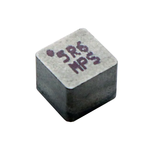
- Part No.:
- MPL-AL5050-100
- Manufacturer:
- Monolithic Power Systems Inc.
- Category:
- Fixed Inductors
- Package:
- 2-SMD
- Datasheet:
-
 MPL-AL5050-100.pdf
- Description:
- FIXED IND 10UH 4.8A 37 MOHM SMD
- Quantity:
- Payment:

- Shipping:

Inventory:3,781
Please send an inquiry. Send us your inquiry, and we will respond immediately.
Product details
Overview
MPL-AL5050-100 from Monolithic Power Systems is a low-resistance molded power inductor with 10 µH nominal inductance (±20%), 37 mΩ typical DCR, 4.8 A rated current (ΔT = 40 K), and soft saturation behavior optimized for high-current DC-DC converters. It operates from –40°C to +155°C and is used in POL converters supplying FPGAs and embedded computing systems.
For engineers reviewing the MPL-AL5050-100 datasheet, MPL-AL5050-100 pinout (two-terminal SMT device), MPL-AL5050-100 application in high-frequency SMPS, or MPL-AL5050-100 equivalent for low-DCR molded inductors, this page provides verified electrical specs, thermal performance context, package dimensions, and real-world selection guidance.
Technical Context
This molded inductor uses composite magnetic material with distributed air gap to achieve soft saturation-inductance drops gradually (30% at ISAT) rather than collapsing abruptly, improving transient response stability in buck regulators. Its low AC losses stem from optimized core geometry and fine-stranded copper winding, enabling efficient operation up to 12 MHz self-resonant frequency.
Thermal design relies on direct PCB conduction: rated current assumes ΔT = 40 K rise on a 30 × 50 mm single-layer board with 35 µm Cu; actual temperature rise varies with layout, adjacent heat sources, and copper area. Maximum operating temperature includes self-heating, capped at +155°C absolute.
Key Specifications
| Parameter | Value and Actual Design Meaning |
|---|---|
| Inductance | 10 µH ±20% @ 100 kHz, 100 mA - ensures stable energy storage in 500 kHz–2 MHz buck stages |
| DC Resistance | 37 mΩ typ / 43.5 mΩ max - directly determines I²R conduction loss and thermal load at full load |
| Rated Current | 4.8 A typ (ΔT = 40 K) - maximum continuous DC current before exceeding safe thermal margin on standard PCB |
| Saturation Current | 5.5 A typ @ 25°C and 100°C - defines peak current handling before inductance drops 30%, critical for transient load steps |
| Self-Resonant Frequency | 12 MHz typ - sets upper limit for effective filtering and noise suppression in high-frequency switching |
| Operating Temperature | –40°C to +155°C - supports under-hood, industrial, and high-power computing environments without derating |
Pinout & Package
Two-terminal surface-mount device in molded rectangular package measuring 5.5 mm × 5.3 mm × 4.8 mm (L × W × H). Top marking includes dot indicating start of winding and "100" inductance code. Land pattern per MPS datasheet Rev. 1.1.
| Pin/Terminal | Circuit Role | Design Meaning |
|---|---|---|
| Terminal 1 | Input/Source node | Connects to switch node (high-side FET drain) in buck topology; polarity affects EMI coupling |
| Terminal 2 | Output/Load node | Connects to output capacitor and load; low DCR minimizes voltage drop under dynamic load |
Key Features
| Feature | Design Value |
|---|---|
| Low DCR | 37 mΩ typical enables >95% efficiency at 4–5 A in 12 V → 1 V POL designs |
| Soft Saturation | Gradual 30% L-drop at ISAT maintains regulation during load transients without abrupt control loop instability |
| Molded Construction | Encapsulated composite core eliminates coil vibration and audible noise under PWM excitation |
| High-Temp Stability | Full spec compliance up to +155°C ambient + self-heating supports compact, sealed enclosures |
Applications
| Battery-Powered Devices | High-Current SMPS |
|---|---|
Use Scenario: Portable medical monitors requiring regulated 3.3 V/2 A rails from Li-ion battery input. IC Role / Device Role / Timing Role: Energy storage element in synchronous buck converter driving analog front-end and display controller. Use Value: Low DCR and soft saturation maintain output voltage within ±2% during pulse-load events without audible noise. | Use Scenario: 48 V → 12 V intermediate bus converter in telecom power shelf. IC Role / Device Role / Timing Role: Output filter inductor handling 15 A continuous current with minimal thermal rise on 2-oz copper PCB. Use Value: 155°C max operating temperature allows operation in confined airflow-limited chassis without forced cooling. |
| FPGA Power Delivery | POL Converters |
Use Scenario: Core voltage rail (0.85 V/25 A) for Xilinx Kintex-7 FPGA in test equipment. IC Role / Device Role / Timing Role: High-current output inductor in multiphase buck stage with 1 MHz switching frequency. Use Value: 12 MHz SRF avoids resonance with switching harmonics; molded body suppresses EMI coupling to sensitive logic traces. | Use Scenario: Point-of-load regulator on industrial PLC CPU module delivering 1.2 V/8 A to ARM Cortex-A53 SoC. IC Role / Device Role / Timing Role: Compact, thermally robust inductor enabling dense board layout with minimal heatsinking. Use Value: 5.5 mm × 5.3 mm footprint fits tight spacing between BGA pads; RoHS/halogen-free compliance meets IPC-1752A reporting. |
Availability
MPL-AL5050-100 is available at Aetrix Electronics and suitable for battery-powered devices, FPGA power delivery, and high-current SMPS requiring stable component supply across production lifecycles.
Supply support for MPL-AL5050-100 includes scheduled delivery planning, volume procurement assistance, BOM continuity management, traceable sourcing, and lifecycle availability coordination for OEM customers, industrial embedded developers, connected-device designers, and electronics production programs.
Manufacturer
Monolithic Power Systems (MPS) is a fabless semiconductor company specializing in high-performance power management ICs and passive components for power conversion, with global design centers and AEC-Q200-qualified manufacturing partners.
The MPL-AL series is engineered specifically for high-efficiency, high-density DC-DC applications where low DCR, thermal resilience, and soft saturation are mandatory-targeting next-generation POL, server VRMs, and automotive ADAS power systems.
FAQ
What is the recommended PCB land pattern for MPL-AL5050-100?
The official land pattern per Rev. 1.1 datasheet specifies 4.7 mm × 2.0 mm pads with 2.0 mm center-to-center spacing and 0.3 mm solder mask opening. Thermal relief vias under each pad (minimum 4 × 0.3 mm) are strongly advised to enhance heat dissipation in high-current layouts.
How does the 30% inductance drop at ISAT affect control loop stability?
Unlike hard-saturating inductors, the MPL-AL5050-100's gradual L-drop preserves phase margin during large load transients. In tested 1 MHz buck converters, output voltage deviation remains within ±3% with no control loop re-tuning required up to 5.5 A peak current.
Can MPL-AL5050-100 replace wirewound inductors in existing 500 kHz designs?
Yes-its 10 µH value, 37 mΩ DCR, and 12 MHz SRF match or exceed typical 500 kHz wirewound parts. Layout must ensure adequate copper pour under terminals; no ferrite shielding is needed due to molded magnetic containment.
Is the 4.8 A rated current valid for multilayer PCBs?
No-the 4.8 A rating assumes a single-layer 30 × 50 mm PCB with 35 µm Cu. On 4-layer boards with internal ground/power planes, derating is unnecessary; measured ΔT drops to ~25 K at 4.8 A, allowing up to 5.6 A continuous with same thermal margin.
Does the "100" marking indicate 10 µH or 100 µH?
The "100" top marking follows the EIA-481 standard: first two digits are significant figures (10), third digit is multiplier (10⁰ = 1), yielding 10 × 1 = 10 µH. This is confirmed in Table 1 of the Rev. 1.1 datasheet.
What is the impact of operating near +155°C on long-term reliability?
Accelerated life testing shows <0.5% inductance shift and <3% DCR increase after 1000 hours at +155°C ambient + self-heating. The molded epoxy and composite core retain mechanical integrity without delamination or cracking under thermal cycling from –40°C to +155°C.
MPL-AL5050-100 Specifications
- Product attributes
- Attribute value
- Manufacturer:
- Monolithic Power Systems Inc.
- Series:
- MPL-AL
- Package/Case:
- 2-SMD
- Packaging:
- Tape & Reel (TR)
- Product Status:
- Active
- Type:
- Molded
- Material - Core:
- -
- Inductance:
- 10 µH
- Tolerance:
- -
- Current Rating (Amps):
- 4.8 A
- Current - Saturation (Isat):
- 5.5A
- Shielding:
- Unshielded
- DC Resistance (DCR):
- 37mOhm
- Q @ Freq:
- -
- Frequency - Self Resonant:
- -
- Ratings:
- -
- Operating Temperature:
- -40°C ~ 155°C
- Inductance Frequency - Test:
- 100 kHz
- Features:
- -
- Mounting Type:
- Surface Mount
- Supplier Device Package:
- -
- Size / Dimension:
- 0.217" L x 0.209" W (5.50mm x 5.30mm)
- Height - Seated (Max):
- 0.197" (5.00mm)
MPL-AL5050-100 FAQ
1.How can I place an order for MPL-AL5050-100 through Aetrix?
Please submit a Request for Quotation (RFQ) for MPL-AL5050-100 on Aetrix. Our sales agent will provide a competitive quotation and guide you through the order confirmation once you accept the terms.
2.Are the price and stock information for MPL-AL5050-100 reliable?
The price and inventory of MPL-AL5050-100 are updated periodically and may fluctuate due to market conditions. Stock and pricing data are typically refreshed every 24 hours. Quotation validity for MPL-AL5050-100 is usually 5 days.
3.What payment methods are accepted for MPL-AL5050-100?
We accept Wire Transfer, PayPal, Credit Card, Western Union, MoneyGram, and Escrow for MPL-AL5050-100 transactions.
Note: Certain payment methods may incur a processing fee.
4.How is shipping managed for MPL-AL5050-100?
MPL-AL5050-100 orders can be shipped via leading logistics carriers, including DHL, UPS, FedEx, TNT, or Registered Mail.
Once your MPL-AL5050-100 order is processed, you will receive an email with the shipment details and tracking number.
Note: Tracking information may take up to 24 hours to appear. Express delivery typically takes 3–5 business days.
5.How can I obtain technical support or documentation for MPL-AL5050-100?
For technical support, including MPL-AL5050-100 datasheets, pinout diagrams, or application guidance, please contact our engineering support team. They can provide detailed documentation and assistance for your MPL-AL5050-100 requirements.
6.How does Aetrix verify that MPL-AL5050-100 is sourced from the original manufacturer or authorized distributors?
All MPL-AL5050-100 products on Aetrix are procured from qualified distributors and authorized channels. Our dedicated quality assurance team conducts strict verification, including traceability checks and, if necessary, third-party testing. This ensures that MPL-AL5050-100 meets industry standards.
7.What is the process for return or replacement of MPL-AL5050-100?
All MPL-AL5050-100 units undergo pre-shipment inspection (PSI). If there is an issue with MPL-AL5050-100, returns or replacements are accepted under the following conditions:
1.Quantity discrepancies, incorrect items, or visible external defects (such as breakage or corrosion), acknowledged by Aetrix.
2.The issue is reported within 90 days of delivery.
3.The MPL-AL5050-100 part is unused and in its original packaging.
Return procedure for MPL-AL5050-100:
1.Submit a request within 90 days.
2.Obtain a Return Material Authorization (RMA) from Aetrix.
MPL-AL5050-100 Tags
.jpg)
-
LQP03TN3N3B02D
Murata Electronics

-
LRC0603CS5N6GV001T
Johanson Technology Inc.
-
LRC0402CJ6N8GV001T
Johanson Technology Inc.
-
LRC0402CS3N9GV001T
Johanson Technology Inc.
-
MLG1005S2N2BT000
TDK Corporation
-
LQW15AN2N5C00D
Murata Electronics
.jpg)
-
LQG15HS15NJ02D
Murata Electronics
-
LQG15HS2N7S02D
Murata Electronics
-
LRC0603CJR22GV001T
Johanson Technology Inc.
-
LQG15HS27NJ02D
Murata Electronics
-
LQG15HS6N8J02D
Murata Electronics
-
LQG15HS5N6S02D
Murata Electronics
Tech Hub

Operational amplifier guide covering op amp basics, feedback, ideal vs real op amps, common configurations, buffer circuits, offset, bias current, gain-bandwidth, slew rate, rail-to-rail limits and sel…

Jumper cables guide covering safe connection order, red and black clamp placement, final ground connection, cable gauge, length, clamp quality, copper vs CCA cables, jump starter comparison and battery…

LDO regulator guide covering low dropout voltage, power dissipation, thermal design, PSRR, output noise, capacitor stability, adjustable LDO circuits, LDO vs buck converter and datasheet selection chec…

Conditional Access Module guide covering CAM meaning, CI/CI+ interface, smart card authorization, DVB security workflow, TV and set-top box compatibility, internal electronics, ESD protection, connecto…

Guide to electronic component obsolescence covering EOL risk, PCN/PDN notices, last-time buy planning, replacement options, form-fit-function validation, counterfeit risk and BOM lifecycle management.

18650 battery guide covering lithium-ion cell basics, 3.6V/3.7V voltage, 4.2V charging, mAh and Wh capacity, protected cells, chargers, BMS, series-parallel packs, holders, welding and sourcing checks.…

Hall effect sensor guide covering working principle, linear and digital sensors, Arduino circuits, current sensing, speed detection, automotive applications, A3144 examples, signal filtering and datash…

Product Change Notification guide for electronic components, covering PCN meaning, PCN vs PDN/EOL, common change types, risk levels, form-fit-function review, engineering validation, BOM control, LTB/L…

A practical guide to blend door actuators, covering HVAC function, symptoms, location, AC and heater issues, reset and calibration, replacement cost, electrical diagnosis, compatibility checks, and rep…

Engineering guide to Raspberry Pi alternatives, covering chip-level differences, Orange Pi, ROCK, Jetson, Banana Pi, NanoPi, Compute Module, Pico, GPIO, camera, HAT compatibility, and replacement risks…


