
 My Inquiry
 My Account


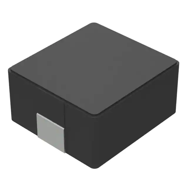
Monolithic Power Systems Inc. MPL-AL6060-150
- Part No.:
- MPL-AL6060-150
- Manufacturer:
- Monolithic Power Systems Inc.
- Category:
- Fixed Inductors
- Package:
- 2-SMD
- Datasheet:
-
 MPL-AL6060-150.pdf
- Description:
- FIXED IND 15UH 5.8A 35 MOHM SMD
- Quantity:
- Payment:

- Shipping:

Inventory:3,192
Please send an inquiry. Send us your inquiry, and we will respond immediately.
Product details
Overview
MPL-AL6060-150 from Monolithic Power Systems is a low-resistance molded power inductor with 15 µH nominal inductance, 35 mΩ typical DCR, 5.8 A rated current (ΔT = 40 K), and +155°C maximum operating temperature, designed for high-current DC-DC converter output filtering in POL and FPGA power rails.
For engineers reviewing the MPL-AL6060-150 datasheet, MPL-AL6060-150 pinout (though non-pin device), MPL-AL6060-150 application in high-frequency SMPS, or MPL-AL6060-150 equivalent, key selection factors include soft saturation behavior, low AC losses at 100 kHz–10 MHz, thermal stability up to 155°C, and RoHS/REACH-compliant halogen-free construction.
Technical Context
This molded inductor uses composite magnetic material with distributed air gap to achieve soft saturation-inductance drops gradually to 70% of nominal at ISAT-enabling predictable current limiting in buck converter output stages. Its 6.6 mm × 6.4 mm × 4.8 mm footprint supports high-density PCB layouts while maintaining thermal derating integrity across -40°C to +155°C ambient.
Designed for switching frequencies up to 10 MHz (typical self-resonant frequency), it delivers stable inductance under DC bias and exhibits low audible noise due to fully potted construction and minimized magnetostrictive vibration. The 35 µm copper PCB test condition (30 × 50 mm single-layer) defines its rated current specification.
Key Specifications
| Parameter | Value and Actual Design Meaning |
|---|---|
| Inductance | 15 µH ±20% @ 100 kHz, 100 mA - ensures stable energy storage in 300–2000 kHz buck converters |
| DC Resistance | 35 mΩ typ / 42 mΩ max - minimizes conduction loss and thermal rise in high-current paths |
| Limited Current | 5.8 A typ (ΔT = 40 K) - defines continuous DC current before exceeding 40 K temperature rise on standard PCB |
| Saturation Current | 5.5 A typ @ 25°C & 100°C - indicates usable peak current before 30% inductance drop under bias |
| Operating Temp | -40°C to +155°C - supports operation in automotive under-hood, industrial motor drives, and high-power computing |
| Self-Resonant Freq | 10 MHz typ - allows use in high-frequency SMPS without parasitic impedance dominance |
Pinout & Package
Package: Molded SMD inductor, 6.6 mm × 6.4 mm × 4.8 mm (L × W × H), bottom-surface mounting with two solder terminals. No leads or pins; terminals are exposed copper pads on underside per land pattern (A = 5.6 mm ref, B = 2.5 mm ref, C = 5.6 mm ref).
| Terminal | Circuit Role | Design Meaning |
|---|---|---|
| Pad 1 | Input/Source terminal | Connects to switch node (high-side FET drain) in buck topology; carries pulsed current |
| Pad 2 | Output/Load terminal | Connects to output capacitor and load; provides low-impedance return path for filtered DC current |
Key Features
| Feature | Design Value |
|---|---|
| Soft saturation profile | Inductance declines gradually to 70% at ISAT-enables controlled current limiting without abrupt collapse in transient response |
| Low AC losses | Optimized core composition reduces eddy current and hysteresis loss at 100 kHz–5 MHz-improves efficiency in high-frequency POL converters |
| Molded construction | Full epoxy encapsulation eliminates coil microphonics and suppresses audible noise in battery-powered devices |
| High thermal stability | Rated for +155°C max case temperature-maintains performance in thermally constrained FPGA and ASIC power delivery networks |
Applications
| Battery-Powered Devices | High-Current SMPS |
|---|---|
Use Scenario: Portable medical monitors requiring ultra-low-noise power for analog front-ends and ADCs. IC Role / Device Role / Timing Role: Output filter inductor in 2 MHz, 5 A buck converter supplying 1.2 V to mixed-signal SoC. Use Value: Low audible noise and stable 15 µH value under DC bias ensure clean rail without interference in sensitive measurement circuits. | Use Scenario: Industrial PLC I/O module with 12 V input, 3.3 V/5 A output for fieldbus interface ICs. IC Role / Device Role / Timing Role: Energy storage element in high-current synchronous buck stage operating at 500 kHz. Use Value: 35 mΩ DCR and soft saturation enable >92% efficiency and predictable overcurrent protection without output voltage collapse. |
| FPGA Power Delivery | POL Converters |
Use Scenario: Core voltage rail (0.85 V/12 A) for Xilinx Artix-7 FPGA in edge AI inference accelerator. IC Role / Device Role / Timing Role: Main output inductor in multiphase buck controller with 1 MHz switching frequency. Use Value: Stable inductance up to 100°C ambient and low AC loss preserve regulation accuracy during burst-mode compute loads. | Use Scenario: Point-of-load regulator on server motherboard supplying DDR4 memory termination voltage (VTT). IC Role / Device Role / Timing Role: Final-stage filtering inductor for 3 A, 1.2 V VTT converter running at 1.5 MHz. Use Value: Compact 6.6 × 6.4 mm footprint enables dense placement near memory modules while sustaining 155°C max operating temperature. |
Availability
MPL-AL6060-150 is available at Aetrix Electronics and suitable for battery-powered devices, high-current SMPS, and FPGA power delivery systems requiring stable component supply with guaranteed long-term manufacturability.
Supply support for MPL-AL6060-150 includes scheduled delivery planning, volume procurement assistance, BOM continuity management, traceable sourcing, and lifecycle availability coordination for OEM customers, industrial embedded developers, connected-device designers, and electronics production programs.
Manufacturer
Monolithic Power Systems (MPS) is a fabless semiconductor company specializing in high-performance power management ICs and passive components, headquartered in Kirkland, WA, with global design and support centers.
The MPL-AL series is MPS's molded power inductor product line, engineered specifically for high-efficiency, high-density DC-DC conversion in space-constrained and thermally demanding applications such as computing, industrial automation, and telecom infrastructure.
FAQ
What is the thermal test condition used to specify rated current?
The rated current (IR = 5.8 A) is defined by a 40 K temperature rise measured on a single-layer PCB (30 × 50 mm, 35 µm Cu). Real-world thermal performance depends on PCB copper area, layer count, airflow, and proximity to heat sources-designers should validate with thermal imaging under actual layout conditions.
Does MPL-AL6060-150 have polarity or winding direction marking?
Yes-the top marking includes a dot indicating the start of winding. This polarity matters in multi-phase interleaved designs where phase alignment affects ripple cancellation; incorrect orientation may increase output ripple and reduce EMI performance.
How does saturation current change with ambient temperature?
ISAT is specified at both 25°C (5.5 A) and 100°C (5.5 A), indicating minimal thermal drift in saturation threshold. This stability arises from the composite core's low temperature coefficient and uniform thermal distribution within the molded package.
Can this inductor be used in automotive applications?
Yes-its -40°C to +155°C operating range, AEC-Q200-aligned construction (halogen-free, RoHS/REACH compliant), and robust molded body meet requirements for under-dash infotainment and ADAS domain controllers, provided board-level thermal design stays within spec.
What is the significance of the 10 MHz self-resonant frequency?
A 10 MHz SRF means the inductor behaves predictably as an inductive element up to that frequency. In practice, it remains effective in buck converters switching up to ~2 MHz; above that, parasitic capacitance begins dominating impedance, reducing filtering efficacy and increasing EMI risk.
Is reflow soldering supported, and what profile is recommended?
Yes-MPL-AL6060-150 is qualified for lead-free reflow per JEDEC J-STD-020. Peak temperature must not exceed 260°C for ≤30 seconds. Thermal shock resistance is ensured by molded epoxy encapsulation; no special pre-bake is required for standard humidity levels.
MPL-AL6060-150 Specifications
- Product attributes
- Attribute value
- Manufacturer:
- Monolithic Power Systems Inc.
- Series:
- MPL-AL
- Package/Case:
- 2-SMD
- Packaging:
- Tape & Reel (TR)
- Product Status:
- Active
- Type:
- Molded
- Material - Core:
- -
- Inductance:
- 15 µH
- Tolerance:
- -
- Current Rating (Amps):
- 5.8 A
- Current - Saturation (Isat):
- 5.5A
- Shielding:
- Unshielded
- DC Resistance (DCR):
- 35mOhm
- Q @ Freq:
- -
- Frequency - Self Resonant:
- -
- Ratings:
- -
- Operating Temperature:
- -40°C ~ 155°C
- Inductance Frequency - Test:
- 100 kHz
- Features:
- -
- Mounting Type:
- Surface Mount
- Supplier Device Package:
- -
- Size / Dimension:
- 0.260" L x 0.252" W (6.60mm x 6.40mm)
- Height - Seated (Max):
- 0.236" (6.00mm)
MPL-AL6060-150 FAQ
1.How can I place an order for MPL-AL6060-150 through Aetrix?
Please submit a Request for Quotation (RFQ) for MPL-AL6060-150 on Aetrix. Our sales agent will provide a competitive quotation and guide you through the order confirmation once you accept the terms.
2.Are the price and stock information for MPL-AL6060-150 reliable?
The price and inventory of MPL-AL6060-150 are updated periodically and may fluctuate due to market conditions. Stock and pricing data are typically refreshed every 24 hours. Quotation validity for MPL-AL6060-150 is usually 5 days.
3.What payment methods are accepted for MPL-AL6060-150?
We accept Wire Transfer, PayPal, Credit Card, Western Union, MoneyGram, and Escrow for MPL-AL6060-150 transactions.
Note: Certain payment methods may incur a processing fee.
4.How is shipping managed for MPL-AL6060-150?
MPL-AL6060-150 orders can be shipped via leading logistics carriers, including DHL, UPS, FedEx, TNT, or Registered Mail.
Once your MPL-AL6060-150 order is processed, you will receive an email with the shipment details and tracking number.
Note: Tracking information may take up to 24 hours to appear. Express delivery typically takes 3–5 business days.
5.How can I obtain technical support or documentation for MPL-AL6060-150?
For technical support, including MPL-AL6060-150 datasheets, pinout diagrams, or application guidance, please contact our engineering support team. They can provide detailed documentation and assistance for your MPL-AL6060-150 requirements.
6.How does Aetrix verify that MPL-AL6060-150 is sourced from the original manufacturer or authorized distributors?
All MPL-AL6060-150 products on Aetrix are procured from qualified distributors and authorized channels. Our dedicated quality assurance team conducts strict verification, including traceability checks and, if necessary, third-party testing. This ensures that MPL-AL6060-150 meets industry standards.
7.What is the process for return or replacement of MPL-AL6060-150?
All MPL-AL6060-150 units undergo pre-shipment inspection (PSI). If there is an issue with MPL-AL6060-150, returns or replacements are accepted under the following conditions:
1.Quantity discrepancies, incorrect items, or visible external defects (such as breakage or corrosion), acknowledged by Aetrix.
2.The issue is reported within 90 days of delivery.
3.The MPL-AL6060-150 part is unused and in its original packaging.
Return procedure for MPL-AL6060-150:
1.Submit a request within 90 days.
2.Obtain a Return Material Authorization (RMA) from Aetrix.
MPL-AL6060-150 Tags
.jpg)
-
LQP03TN3N3B02D
Murata Electronics

-
LRC0603CS5N6GV001T
Johanson Technology Inc.
-
LRC0402CJ6N8GV001T
Johanson Technology Inc.
-
LRC0402CS3N9GV001T
Johanson Technology Inc.
-
MLG1005S2N2BT000
TDK Corporation
-
LQW15AN2N5C00D
Murata Electronics
.jpg)
-
LQG15HS15NJ02D
Murata Electronics
-
LQG15HS2N7S02D
Murata Electronics
-
LRC0603CJR22GV001T
Johanson Technology Inc.
-
LQG15HS27NJ02D
Murata Electronics
-
LQG15HS6N8J02D
Murata Electronics
-
LQG15HS5N6S02D
Murata Electronics
Tech Hub

An SR latch stores one bit through cross-coupled feedback. This engineering reference covers NOR and NAND implementations, truth tables, forbidden-state recovery, gated operation, switch debouncing, fa…

Latch circuits retain one bit through feedback. This technical reference covers SR and D latches, truth tables, transparency, timing limits, latch-versus-flip-flop behavior, applications and common log…

An engineering guide to LED driver operation, constant-current and constant-voltage outputs, linear and switching topologies, dimming, IC selection, calculations, replacement compatibility, and fault c…

Operational amplifier guide covering op amp basics, feedback, ideal vs real op amps, common configurations, buffer circuits, offset, bias current, gain-bandwidth, slew rate, rail-to-rail limits and sel…

Jumper cables guide covering safe connection order, red and black clamp placement, final ground connection, cable gauge, length, clamp quality, copper vs CCA cables, jump starter comparison and battery…

LDO regulator guide covering low dropout voltage, power dissipation, thermal design, PSRR, output noise, capacitor stability, adjustable LDO circuits, LDO vs buck converter and datasheet selection chec…

Conditional Access Module guide covering CAM meaning, CI/CI+ interface, smart card authorization, DVB security workflow, TV and set-top box compatibility, internal electronics, ESD protection, connecto…

Guide to electronic component obsolescence covering EOL risk, PCN/PDN notices, last-time buy planning, replacement options, form-fit-function validation, counterfeit risk and BOM lifecycle management.

18650 battery guide covering lithium-ion cell basics, 3.6V/3.7V voltage, 4.2V charging, mAh and Wh capacity, protected cells, chargers, BMS, series-parallel packs, holders, welding and sourcing checks.…

Hall effect sensor guide covering working principle, linear and digital sensors, Arduino circuits, current sensing, speed detection, automotive applications, A3144 examples, signal filtering and datash…


