
 My Inquiry
 My Account


Monolithic Power Systems Inc. MPL-AT2512-R33
- Part No.:
- MPL-AT2512-R33
- Manufacturer:
- Monolithic Power Systems Inc.
- Category:
- Fixed Inductors
- Package:
- 2-SMD, J-Lead
- Datasheet:
-
 MPL-AT2512-R33.pdf
- Description:
- FIXED IND 330NH 6.4A 13.5MOHM SM
- Quantity:
- Payment:

- Shipping:

Inventory:1,980
Please send an inquiry. Send us your inquiry, and we will respond immediately.
Product details
Overview
MPL-AT2512-R33 from Monolithic Power Systems is a low-profile molded power inductor with 0.33 µH nominal inductance (±20%), 13 mΩ typical DCR, 6.4 A rated current (ΔT = 40 K), and 7.8 A saturation current at both 25°C and 100°C ambient - optimized for high-frequency DC-DC converters in space-constrained portable electronics.
For engineers reviewing the MPL-AT2512-R33 datasheet, MPL-AT2512-R33 package dimensions, MPL-AT2512-R33 thermal derating curve, or MPL-AT2512-R33 alternative inductors for 1–3 MHz buck regulators, this page delivers verified electrical specs, application-specific performance context, and supply-chain-ready availability details.
Technical Context
This molded SMD inductor uses soft-saturation ferrite core material to maintain gradual inductance roll-off under high DC bias, enabling stable regulation in high-switching-frequency buck converters. Its 2.5 mm × 2.0 mm × 1.2 mm footprint supports ultra-thin PCB designs while sustaining operation from –40°C to +125°C (including self-heating).
Designed for continuous conduction mode (CCM) operation, it delivers low audible noise due to constrained magnetostrictive effects and exhibits a typical self-resonant frequency of 132 MHz - well above typical SMPS switching ranges (1–3 MHz), ensuring minimal impedance deviation across operating bandwidth.
Key Specifications
| Parameter | Value and Actual Design Meaning |
|---|---|
| Inductance | 0.33 µH ±20% at 100 kHz / 100 mA - ensures predictable energy storage in 1–3 MHz buck stages. |
| DC Resistance | 13 mΩ typical - limits I²R conduction loss to <530 mW at 6.4 A, supporting >95% efficiency in compact converters. |
| Saturation Current | 7.8 A at 25°C and 100°C - maintains ≥70% L up to full load in thermally aggressive environments. |
| Rated Current | 6.4 A - causes 40 K temperature rise on standard 35 µm Cu single-layer PCB (30×50 mm), defining safe continuous DC handling. |
| Operating Temp | –40°C to +125°C - includes self-heating margin; enables deployment in battery-powered wearables and IoT edge nodes. |
| Self-Resonant Freq | 132 MHz typical - places resonance far above switching frequencies, preserving intended inductive behavior. |
Pinout & Package
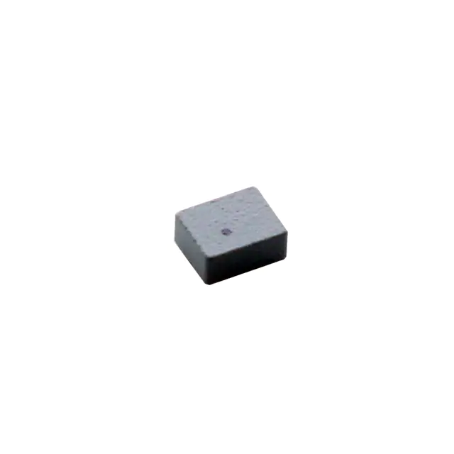
As a passive two-terminal surface-mount inductor, MPL-AT2512-R33 has no active pins or signal assignments. It features a molded epoxy-coated rectangular package measuring 2.50 mm × 2.00 mm × 1.20 mm max, with top-side dot marking indicating start of winding. Recommended land pattern: 2.30 mm × 0.90 mm pads with 0.50 mm spacing.
| Terminal | Circuit Role | Design Meaning |
|---|---|---|
| Terminal 1 | Input/Source side connection | Connected to switch node or input rail; polarity-sensitive for EMI reduction in coupled layouts. |
| Terminal 2 | Output/Load side connection | Connected to output filter capacitor or load; orientation affects magnetic coupling and thermal path to PCB. |
Key Features
| Feature | Design Value |
|---|---|
| Low profile height | 1.20 mm max - enables integration into sub-1.5 mm total board thickness designs for wearables and hearing aids. |
| Soft saturation characteristic | Gradual 30% L drop at ISAT - prevents abrupt converter instability during transient overloads. |
| Stable high-temp performance | No degradation in ISAT between 25°C and 100°C ambient - eliminates thermal derating in sealed enclosures. |
| Low audible noise | Molded construction suppresses magnetostriction-induced coil vibration - critical for quiet medical and consumer audio devices. |
| Halogen-free & RoHS/REACH | Compliant with global environmental directives - supports export readiness and sustainability requirements. |
Applications
| Wearable Power Management | IoT Edge Node DC-DC |
|---|---|
Use Scenario: Powering ARM Cortex-M microcontrollers and BLE radios in smartwatches with tight height budgets. IC Role / Device Role / Timing Role: Output filter inductor in 2 MHz synchronous buck converter supplying 1.8 V/3.3 V rails. Use Value: 1.2 mm height enables full system stack-up ≤1.4 mm; soft saturation prevents brownouts during radio transmit bursts. | Use Scenario: Regulating battery voltage for LoRaWAN sensor nodes operating intermittently for years on coin cells. IC Role / Device Role / Timing Role: Energy-storage element in high-efficiency buck converter driving ultra-low-quiescent PMICs. Use Value: 13 mΩ DCR minimizes no-load losses; -40°C to +125°C rating ensures field reliability across outdoor deployments. |
| Portable Medical Devices | USB-C PD Input Filtering |
Use Scenario: Providing clean 5 V/3.3 V rails in handheld diagnostic tools requiring silent operation. IC Role / Device Role / Timing Role: Low-noise output choke in 1.5 MHz buck stage powering analog front-end and ADCs. Use Value: Molded construction eliminates audible coil whine; stable L vs. temp avoids calibration drift in precision sensors. | Use Scenario: Filtering high-frequency ripple from USB-C PD 9 V/15 V/20 V inputs before downstream buck controllers. IC Role / Device Role / Timing Role: Input EMI filter inductor for wide-input buck converters handling variable PD profiles. Use Value: 132 MHz SRF rejects >10 MHz switching noise; 7.8 A ISAT accommodates 3 A–5 A PD fast-charging transients. |
Equivalent & Alternatives
The following parts are listed as comparable options for similar low-profile molded inductor applications.
| Alternative Part | Technical Difference | Application Difference | Selection Advice |
|---|---|---|---|
| MPL-AT2512-R47 | 0.47 µH ±20%, 14 mΩ RDC, 5.8 A IR, 6.4 A ISAT - higher inductance, lower current rating. | Better suited for lower-switching-frequency (≤1 MHz) or higher-output-voltage buck stages where ripple current is smaller. | Select when target output ripple requires higher L and thermal budget allows reduced IR. |
| TDK VLS201610ET-330M | 0.33 µH ±20%, 22 mΩ RDC, 4.5 A IR, 5.5 A ISAT - larger 2.0×1.6×1.0 mm footprint, higher DCR, lower current capability. | Acceptable where board area permits and efficiency targets allow ~70% higher conduction loss. | Choose only if MPL-AT2512-R33 is unavailable and 22 mΩ DCR meets system efficiency goals. |
Compared with MPL-AT2512-R47 and TDK VLS201610ET-330M, the MPL-AT2512-R33 delivers the highest current density (6.4 A in 2.5×2.0 mm) and lowest DCR among 0.33 µH molded inductors in its height class - making it optimal for thermally constrained, high-efficiency portable power designs.
Availability
MPL-AT2512-R33 is available at Aetrix Electronics and suitable for wearable power management, IoT edge node DC-DC conversion, and portable medical device applications requiring stable component supply, consistent parametric performance, and long-term production continuity.
Supply support for MPL-AT2512-R33 includes scheduled delivery planning, volume procurement assistance, BOM continuity management, traceable sourcing, and lifecycle availability coordination for OEM customers, industrial embedded developers, connected-device designers, and electronics production programs.
Manufacturer
Monolithic Power Systems (MPS) is a fabless semiconductor company specializing in high-performance power management ICs and passive components for power conversion, battery management, and motor control.
The MPL-AT series is engineered specifically for high-frequency, low-profile DC-DC applications in portable and battery-powered systems - emphasizing thermal robustness, miniaturization, and low-noise operation.
FAQ
What is the maximum allowable board temperature rise when operating MPL-AT2512-R33 at its rated current?
The rated current of 6.4 A is defined as the DC current causing a 40 K temperature rise above ambient when mounted on a standardized single-layer PCB (30×50 mm, 35 µm Cu). Total operating temperature must not exceed +125°C, meaning ambient + ΔT ≤ 125°C - e.g., at 85°C ambient, max ΔT = 40 K is permitted.
Does MPL-AT2512-R33 support reflow soldering per J-STD-020?
Yes - MPL-AT2512-R33 is qualified for standard lead-free reflow profiles (peak temperature ≤260°C, 20–40 sec dwell). The molded epoxy body withstands thermal cycling without cracking or delamination, and the terminations meet IPC-J-STD-002B solderability requirements.
How does the 7.8 A saturation current at 100°C compare to typical ferrite inductors?
Unlike many ferrite inductors whose ISAT degrades significantly above 60°C, MPL-AT2512-R33 maintains identical 7.8 A ISAT at both 25°C and 100°C - reflecting proprietary core material formulation that minimizes permeability shift with temperature, critical for sealed or high-ambient environments.
Can MPL-AT2512-R33 be used in automotive cabin applications?
No - while its –40°C to +125°C operating range overlaps with some automotive ambient zones, MPL-AT2512-R33 is not AEC-Q200 qualified, lacks automotive-grade screening, and has not undergone vibration, shock, or extended lifetime testing required for automotive use.
Is there a recommended PCB layout for minimizing thermal resistance?
Yes - maximize copper area under both terminals using thermal vias (≥4×0.3 mm diameter) connecting to inner ground/power planes. Avoid placing heat-generating ICs directly adjacent. Maintain ≥1.5 mm clearance from other components to reduce convective heating and ensure airflow around the inductor body.
What is the significance of the dot marking on the top surface?
The dot indicates the start of the internal winding. Maintaining consistent orientation (dot toward switch node) in multi-phase or coupled-inductor layouts reduces common-mode EMI and improves current sharing accuracy - especially important in interleaved buck converters.
MPL-AT2512-R33 Specifications
- Product attributes
- Attribute value
- Manufacturer:
- Monolithic Power Systems Inc.
- Series:
- MPL-AT
- Package/Case:
- 2-SMD, J-Lead
- Packaging:
- Tape & Reel (TR)
- Product Status:
- Active
- Type:
- Molded
- Material - Core:
- -
- Inductance:
- 330 nH
- Tolerance:
- -
- Current Rating (Amps):
- 6.4 A
- Current - Saturation (Isat):
- 8.5A
- Shielding:
- Unshielded
- DC Resistance (DCR):
- 13.5mOhm
- Q @ Freq:
- -
- Frequency - Self Resonant:
- -
- Ratings:
- -
- Operating Temperature:
- -40°C ~ 125°C
- Inductance Frequency - Test:
- 100 kHz
- Features:
- -
- Mounting Type:
- Surface Mount
- Supplier Device Package:
- -
- Size / Dimension:
- 0.098" L x 0.079" W (2.50mm x 2.00mm)
- Height - Seated (Max):
- 0.047" (1.20mm)
MPL-AT2512-R33 FAQ
1.How can I place an order for MPL-AT2512-R33 through Aetrix?
Please submit a Request for Quotation (RFQ) for MPL-AT2512-R33 on Aetrix. Our sales agent will provide a competitive quotation and guide you through the order confirmation once you accept the terms.
2.Are the price and stock information for MPL-AT2512-R33 reliable?
The price and inventory of MPL-AT2512-R33 are updated periodically and may fluctuate due to market conditions. Stock and pricing data are typically refreshed every 24 hours. Quotation validity for MPL-AT2512-R33 is usually 5 days.
3.What payment methods are accepted for MPL-AT2512-R33?
We accept Wire Transfer, PayPal, Credit Card, Western Union, MoneyGram, and Escrow for MPL-AT2512-R33 transactions.
Note: Certain payment methods may incur a processing fee.
4.How is shipping managed for MPL-AT2512-R33?
MPL-AT2512-R33 orders can be shipped via leading logistics carriers, including DHL, UPS, FedEx, TNT, or Registered Mail.
Once your MPL-AT2512-R33 order is processed, you will receive an email with the shipment details and tracking number.
Note: Tracking information may take up to 24 hours to appear. Express delivery typically takes 3–5 business days.
5.How can I obtain technical support or documentation for MPL-AT2512-R33?
For technical support, including MPL-AT2512-R33 datasheets, pinout diagrams, or application guidance, please contact our engineering support team. They can provide detailed documentation and assistance for your MPL-AT2512-R33 requirements.
6.How does Aetrix verify that MPL-AT2512-R33 is sourced from the original manufacturer or authorized distributors?
All MPL-AT2512-R33 products on Aetrix are procured from qualified distributors and authorized channels. Our dedicated quality assurance team conducts strict verification, including traceability checks and, if necessary, third-party testing. This ensures that MPL-AT2512-R33 meets industry standards.
7.What is the process for return or replacement of MPL-AT2512-R33?
All MPL-AT2512-R33 units undergo pre-shipment inspection (PSI). If there is an issue with MPL-AT2512-R33, returns or replacements are accepted under the following conditions:
1.Quantity discrepancies, incorrect items, or visible external defects (such as breakage or corrosion), acknowledged by Aetrix.
2.The issue is reported within 90 days of delivery.
3.The MPL-AT2512-R33 part is unused and in its original packaging.
Return procedure for MPL-AT2512-R33:
1.Submit a request within 90 days.
2.Obtain a Return Material Authorization (RMA) from Aetrix.
MPL-AT2512-R33 Tags
.jpg)
-
LQP03TN3N3B02D
Murata Electronics

-
LRC0603CS5N6GV001T
Johanson Technology Inc.
-
LRC0402CJ6N8GV001T
Johanson Technology Inc.
-
LRC0402CS3N9GV001T
Johanson Technology Inc.
-
MLG1005S2N2BT000
TDK Corporation
-
LQW15AN2N5C00D
Murata Electronics
.jpg)
-
LQG15HS15NJ02D
Murata Electronics
-
LQG15HS2N7S02D
Murata Electronics
-
LRC0603CJR22GV001T
Johanson Technology Inc.
-
LQG15HS27NJ02D
Murata Electronics
-
LQG15HS6N8J02D
Murata Electronics
-
LQG15HS5N6S02D
Murata Electronics
Tech Hub

Operational amplifier guide covering op amp basics, feedback, ideal vs real op amps, common configurations, buffer circuits, offset, bias current, gain-bandwidth, slew rate, rail-to-rail limits and sel…

Jumper cables guide covering safe connection order, red and black clamp placement, final ground connection, cable gauge, length, clamp quality, copper vs CCA cables, jump starter comparison and battery…

LDO regulator guide covering low dropout voltage, power dissipation, thermal design, PSRR, output noise, capacitor stability, adjustable LDO circuits, LDO vs buck converter and datasheet selection chec…

Conditional Access Module guide covering CAM meaning, CI/CI+ interface, smart card authorization, DVB security workflow, TV and set-top box compatibility, internal electronics, ESD protection, connecto…

Guide to electronic component obsolescence covering EOL risk, PCN/PDN notices, last-time buy planning, replacement options, form-fit-function validation, counterfeit risk and BOM lifecycle management.

18650 battery guide covering lithium-ion cell basics, 3.6V/3.7V voltage, 4.2V charging, mAh and Wh capacity, protected cells, chargers, BMS, series-parallel packs, holders, welding and sourcing checks.…

Hall effect sensor guide covering working principle, linear and digital sensors, Arduino circuits, current sensing, speed detection, automotive applications, A3144 examples, signal filtering and datash…

Product Change Notification guide for electronic components, covering PCN meaning, PCN vs PDN/EOL, common change types, risk levels, form-fit-function review, engineering validation, BOM control, LTB/L…

A practical guide to blend door actuators, covering HVAC function, symptoms, location, AC and heater issues, reset and calibration, replacement cost, electrical diagnosis, compatibility checks, and rep…

Engineering guide to Raspberry Pi alternatives, covering chip-level differences, Orange Pi, ROCK, Jetson, Banana Pi, NanoPi, Compute Module, Pico, GPIO, camera, HAT compatibility, and replacement risks…


