
 My Inquiry
 My Account


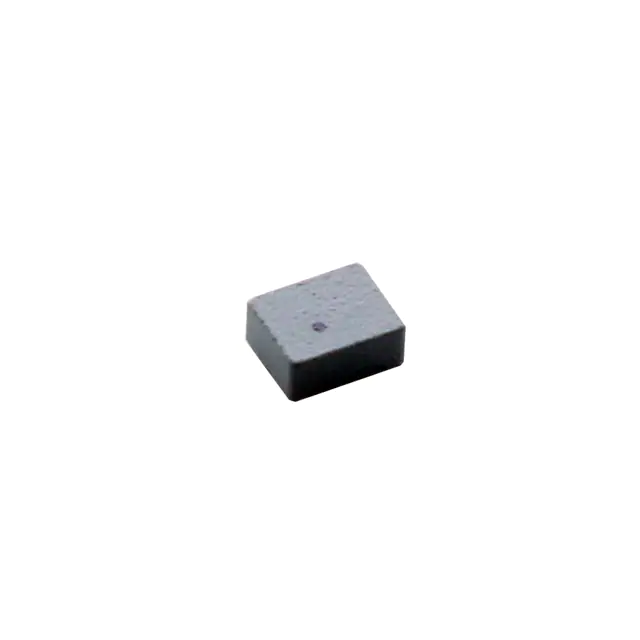
Monolithic Power Systems Inc. MPL-AT2514-2R2
- Part No.:
- MPL-AT2514-2R2
- Manufacturer:
- Monolithic Power Systems Inc.
- Category:
- Fixed Inductors
- Package:
- 2-SMD, J-Lead
- Datasheet:
-
 MPL-AT2514-2R2.pdf
- Description:
- FIXED IND 2.2UH 2.6A 70 MOHM SMD
- Quantity:
- Payment:

- Shipping:

Inventory:2,010
Please send an inquiry. Send us your inquiry, and we will respond immediately.
Product details
Overview
MPL-AT2514-2R2 from Monolithic Power Systems is a low-profile molded power inductor with 2.2 µH nominal inductance (±20%), 70 mΩ typical DCR, 2.6 A rated current (ΔT = 40 K), and 3.4 A saturation current at both 25°C and 100°C ambient - designed for high-frequency DC-DC converters in space-constrained portable electronics.
For engineers reviewing the MPL-AT2514-2R2 datasheet, MPL-AT2514-2R2 pinout (SMD terminals), MPL-AT2514-2R2 application in compact SMPS, or MPL-AT2514-2R2 equivalent for end-of-life mitigation, this page delivers verified electrical specs, thermal behavior context, package dimensions, and direct replacement guidance per MPS official documentation.
Technical Context
This molded SMD inductor uses composite magnetic material with soft saturation characteristics, enabling stable inductance down to 70% of nominal value under peak DC bias - critical for maintaining regulation margin in buck converters operating above 1 MHz. Its 2.5 mm × 2.0 mm × 1.4 mm footprint supports ultra-thin PCB layouts without compromising thermal derating up to +125°C total operating temperature.
Designed for input filtering and energy storage in battery-powered DC-DC stages, it exhibits low audible noise due to constrained core vibration and low AC resistance (typ. 45 MHz self-resonant frequency), with RDC tolerance tightly controlled to ±14 mΩ (70–84 mΩ) to ensure consistent efficiency across production lots.
Key Specifications
| Parameter | Value and Actual Design Meaning |
|---|---|
| Inductance | 2.2 µH ±20% @ 100 kHz, 100 mA - ensures stable loop response in 500 kHz–2 MHz buck regulators |
| RDC typ | 70 mΩ - limits conduction loss to ≤470 mW at 2.6 A, supporting >92% efficiency in 3.3 V output designs |
| Rated Current | 2.6 A (ΔT = 40 K on 35 µm Cu, 30×50 mm PCB) - defines continuous thermal limit under standard layout conditions |
| Saturation Current | 3.4 A @ 25°C & 100°C (L drop = 30%) - enables peak-current-mode control headroom in transient-heavy loads |
| Operating Temp | −40°C to +125°C (including self-heating) - validated for wearable and IoT edge nodes with no derating below 100°C |
| SRF | 45 MHz typ - places resonance well above switching frequencies, avoiding impedance anomalies in 2 MHz designs |
Pinout & Package
Two-terminal surface-mount device in molded rectangular package; no polarity marking required. Dimensions: 2.5 mm (L) × 2.0 mm (W) × 1.4 mm (H); land pattern per MPS Rev. 1.1 drawing - pad length 2.0 mm, width 1.2 mm, spacing 0.8 mm center-to-center.
| Pin/Terminal | Circuit Role | Design Meaning |
|---|---|---|
| Terminal 1 | Input/Source node | Connects to switch node (high-side FET drain) in buck topology; carries full AC+DC current |
| Terminal 2 | Output/Load node | Connects to output capacitor and load; same current magnitude, 180° phase shift relative to Terminal 1 |
Key Features
| Feature | Design Value |
|---|---|
| Low profile (1.4 mm height) | Enables <1.6 mm Z-height PCB stacks in wearables and hearing aids without thermal stack-up penalties |
| Soft saturation curve | Gradual L reduction preserves control-loop stability during load transients - avoids sudden collapse in current-mode controllers |
| Molded composite construction | Eliminates air gaps and winding movement, reducing audible coil whine and mechanical microphonics |
| RoHS/REACH, halogen-free | Complies with IPC-1752A Tier 1 reporting requirements for medical and consumer OEMs targeting EU/US markets |
Applications
| Wearable Power Management | IoT Sensor Node DC-DC |
|---|---|
Use Scenario: Ultra-thin smartwatch PMIC supplying 1.2 V core rail to ARM Cortex-M4 MCU and BLE radio. IC Role / Device Role / Timing Role: Output filter inductor in 2 MHz synchronous buck converter; stores energy during high-side FET ON time and releases it during OFF time. Use Value: 1.4 mm height fits within 1.6 mm chassis clearance; 3.4 A ISAT handles 2.2 A peak burst current from sensor fusion algorithms. | Use Scenario: Battery-powered environmental sensor node using Li-SOCl₂ cell (3.6 V) powering 3.3 V RF transceiver and 1.8 V ADC. IC Role / Device Role / Timing Role: Input filter inductor for 1.5 MHz buck-boost regulator; suppresses high-frequency switching noise before entering analog section. Use Value: 70 mΩ RDC minimizes no-load quiescent loss; −40°C to +125°C rating covers outdoor deployment extremes. |
| Portable Medical Monitor | Wireless Earbud Charging Circuit |
Use Scenario: ECG front-end module requiring clean 2.5 V analog supply derived from 3.7 V Li-ion cell. IC Role / Device Role / Timing Role: Energy storage element in low-noise 1.2 MHz buck converter; filters ripple to meet <10 µVpp analog rail spec. Use Value: Molded construction eliminates audible noise during patient monitoring; soft saturation prevents gain compression in feedback loop. | Use Scenario: Compact charging case delivering 5 V USB-PD to earbuds via integrated buck converter. IC Role / Device Role / Timing Role: Output choke in 2.2 MHz fixed-frequency buck stage stepping 12 V down to 5 V at 1.5 A. Use Value: 2.5 mm × 2.0 mm footprint matches tight board area budget; 45 MHz SRF avoids interaction with 2.2 MHz fundamental and harmonics. |
Equivalent & Alternatives
The following parts are listed as comparable options for similar power inductor applications.
| Alternative Part | Technical Difference | Application Difference | Selection Advice |
|---|---|---|---|
| MPL-AT2512-2R2 | Same inductance (2.2 µH), lower profile (1.2 mm H), 65 mΩ RDC, 2.8 A IR, 3.6 A ISAT - smaller footprint (2.5×2.0×1.2 mm) | Better suited for sub-1.3 mm Z-height designs; slightly higher saturation margin but reduced thermal mass | Select when board height is constrained below 1.35 mm and thermal load is moderate |
| MPX1D0620-2R2 | 2.2 µH, 1.0 mm height, 110 mΩ RDC, 2.0 A IR, 2.5 A ISAT - shielded drum-core, higher DCR, lower saturation | Preferred where EMI shielding is mandatory and efficiency >90% is not required | Choose only if magnetic shielding is prioritized over efficiency and thermal performance |
Compared with MPL-AT2514-2R2, MPL-AT2512-2R2 offers tighter height and improved saturation margin in identical footprint width/length, while MPX1D0620-2R2 trades efficiency and thermal capability for EMI containment - making the AT2512 the recommended direct replacement per MPS end-of-life notice.
Availability
MPL-AT2514-2R2 is available at Aetrix Electronics and suitable for wearable power management, IoT sensor node DC-DC conversion, and portable medical monitor supply rails requiring stable component supply despite its end-of-life status.
Supply support for MPL-AT2514-2R2 includes scheduled delivery planning, volume procurement assistance, BOM continuity management, traceable sourcing, and lifecycle availability coordination for OEM customers, industrial embedded developers, connected-device designers, and electronics production programs.
Manufacturer
Monolithic Power Systems (MPS) is a fabless semiconductor company specializing in high-performance power management ICs and passive components for battery-powered and energy-efficient systems.
The MPL-AT series is engineered specifically for high-frequency, low-profile DC-DC converter applications in portable and wearable electronics - emphasizing thermal robustness, acoustic quietness, and layout flexibility in sub-2 mm height constraints.
FAQ
Is MPL-AT2514-2R2 still in active production?
No. MPS has declared MPL-AT2514-2R2 end-of-life and recommends migration to MPL-AT2512-2R2, which shares identical inductance, tighter height (1.2 mm), and improved thermal metrics. Last-time-buy dates and remaining stock levels are tracked by Aetrix Electronics for legacy design support.
What is the maximum allowable PCB copper thickness for rated current testing?
The rated current (2.6 A) is specified using 35 µm (1 oz) copper on a single-layer 30 mm × 50 mm test board. Thicker copper (e.g., 70 µm) improves heat spreading and may allow >3.0 A continuous operation, but requires validation per actual layout - MPS does not publish derating curves for alternate copper weights.
Does MPL-AT2514-2R2 have polarity or orientation sensitivity?
No. It is a non-polarized two-terminal inductor with symmetric construction. The dot marking indicates start of winding but has no functional impact on circuit operation or thermal performance - placement orientation does not affect inductance, saturation, or DCR.
Can MPL-AT2514-2R2 be used in automotive applications?
Not qualified per AEC-Q200. While its −40°C to +125°C operating range overlaps automotive ambient requirements, it lacks automotive-grade screening (e.g., vibration, thermal cycling, HTOL). For automotive use, MPS recommends the AEC-Q200-qualified MPL-AT2512-A series with equivalent inductance values.
How does soft saturation benefit control-loop stability?
Soft saturation causes gradual inductance decline (to 70% of nominal) under increasing DC bias, preventing abrupt changes in current slew rate and voltage gain. This maintains predictable loop dynamics in peak-current-mode controllers - unlike hard-saturating inductors that induce subharmonic oscillation or cycle skipping near ISAT.
What is the recommended reflow profile for MPL-AT2514-2R2?
MPS specifies JEDEC J-STD-020D-compliant lead-free reflow: peak temperature 260°C for ≤10 seconds, ramp-up ≤3°C/s, ramp-down ≤6°C/s, and time above 217°C of 60–150 seconds. Exceeding these limits risks epoxy cracking or interfacial delamination in the molded body.
MPL-AT2514-2R2 Specifications
- Product attributes
- Attribute value
- Manufacturer:
- Monolithic Power Systems Inc.
- Series:
- MPL-AT
- Package/Case:
- 2-SMD, J-Lead
- Packaging:
- Tape & Reel (TR)
- Product Status:
- Not For New Designs
- Type:
- Molded
- Material - Core:
- -
- Inductance:
- 2.2 µH
- Tolerance:
- -
- Current Rating (Amps):
- 2.6 A
- Current - Saturation (Isat):
- 3.4A
- Shielding:
- Unshielded
- DC Resistance (DCR):
- 70mOhm
- Q @ Freq:
- -
- Frequency - Self Resonant:
- -
- Ratings:
- -
- Operating Temperature:
- -40°C ~ 125°C
- Inductance Frequency - Test:
- 100 kHz
- Features:
- -
- Mounting Type:
- Surface Mount
- Supplier Device Package:
- -
- Size / Dimension:
- 0.098" L x 0.079" W (2.50mm x 2.00mm)
- Height - Seated (Max):
- 0.055" (1.40mm)
MPL-AT2514-2R2 FAQ
1.How can I place an order for MPL-AT2514-2R2 through Aetrix?
Please submit a Request for Quotation (RFQ) for MPL-AT2514-2R2 on Aetrix. Our sales agent will provide a competitive quotation and guide you through the order confirmation once you accept the terms.
2.Are the price and stock information for MPL-AT2514-2R2 reliable?
The price and inventory of MPL-AT2514-2R2 are updated periodically and may fluctuate due to market conditions. Stock and pricing data are typically refreshed every 24 hours. Quotation validity for MPL-AT2514-2R2 is usually 5 days.
3.What payment methods are accepted for MPL-AT2514-2R2?
We accept Wire Transfer, PayPal, Credit Card, Western Union, MoneyGram, and Escrow for MPL-AT2514-2R2 transactions.
Note: Certain payment methods may incur a processing fee.
4.How is shipping managed for MPL-AT2514-2R2?
MPL-AT2514-2R2 orders can be shipped via leading logistics carriers, including DHL, UPS, FedEx, TNT, or Registered Mail.
Once your MPL-AT2514-2R2 order is processed, you will receive an email with the shipment details and tracking number.
Note: Tracking information may take up to 24 hours to appear. Express delivery typically takes 3–5 business days.
5.How can I obtain technical support or documentation for MPL-AT2514-2R2?
For technical support, including MPL-AT2514-2R2 datasheets, pinout diagrams, or application guidance, please contact our engineering support team. They can provide detailed documentation and assistance for your MPL-AT2514-2R2 requirements.
6.How does Aetrix verify that MPL-AT2514-2R2 is sourced from the original manufacturer or authorized distributors?
All MPL-AT2514-2R2 products on Aetrix are procured from qualified distributors and authorized channels. Our dedicated quality assurance team conducts strict verification, including traceability checks and, if necessary, third-party testing. This ensures that MPL-AT2514-2R2 meets industry standards.
7.What is the process for return or replacement of MPL-AT2514-2R2?
All MPL-AT2514-2R2 units undergo pre-shipment inspection (PSI). If there is an issue with MPL-AT2514-2R2, returns or replacements are accepted under the following conditions:
1.Quantity discrepancies, incorrect items, or visible external defects (such as breakage or corrosion), acknowledged by Aetrix.
2.The issue is reported within 90 days of delivery.
3.The MPL-AT2514-2R2 part is unused and in its original packaging.
Return procedure for MPL-AT2514-2R2:
1.Submit a request within 90 days.
2.Obtain a Return Material Authorization (RMA) from Aetrix.
MPL-AT2514-2R2 Tags
.jpg)
-
LQP03TN3N3B02D
Murata Electronics

-
LRC0603CS5N6GV001T
Johanson Technology Inc.
-
LRC0402CJ6N8GV001T
Johanson Technology Inc.
-
LRC0402CS3N9GV001T
Johanson Technology Inc.
-
MLG1005S2N2BT000
TDK Corporation
-
LQW15AN2N5C00D
Murata Electronics
.jpg)
-
LQG15HS15NJ02D
Murata Electronics
-
LQG15HS2N7S02D
Murata Electronics
-
LRC0603CJR22GV001T
Johanson Technology Inc.
-
LQG15HS27NJ02D
Murata Electronics
-
LQG15HS6N8J02D
Murata Electronics
-
LQG15HS5N6S02D
Murata Electronics
Tech Hub

Operational amplifier guide covering op amp basics, feedback, ideal vs real op amps, common configurations, buffer circuits, offset, bias current, gain-bandwidth, slew rate, rail-to-rail limits and sel…

Jumper cables guide covering safe connection order, red and black clamp placement, final ground connection, cable gauge, length, clamp quality, copper vs CCA cables, jump starter comparison and battery…

LDO regulator guide covering low dropout voltage, power dissipation, thermal design, PSRR, output noise, capacitor stability, adjustable LDO circuits, LDO vs buck converter and datasheet selection chec…

Conditional Access Module guide covering CAM meaning, CI/CI+ interface, smart card authorization, DVB security workflow, TV and set-top box compatibility, internal electronics, ESD protection, connecto…

Guide to electronic component obsolescence covering EOL risk, PCN/PDN notices, last-time buy planning, replacement options, form-fit-function validation, counterfeit risk and BOM lifecycle management.

18650 battery guide covering lithium-ion cell basics, 3.6V/3.7V voltage, 4.2V charging, mAh and Wh capacity, protected cells, chargers, BMS, series-parallel packs, holders, welding and sourcing checks.…

Hall effect sensor guide covering working principle, linear and digital sensors, Arduino circuits, current sensing, speed detection, automotive applications, A3144 examples, signal filtering and datash…

Product Change Notification guide for electronic components, covering PCN meaning, PCN vs PDN/EOL, common change types, risk levels, form-fit-function review, engineering validation, BOM control, LTB/L…

A practical guide to blend door actuators, covering HVAC function, symptoms, location, AC and heater issues, reset and calibration, replacement cost, electrical diagnosis, compatibility checks, and rep…

Engineering guide to Raspberry Pi alternatives, covering chip-level differences, Orange Pi, ROCK, Jetson, Banana Pi, NanoPi, Compute Module, Pico, GPIO, camera, HAT compatibility, and replacement risks…


