
 My Inquiry
 My Account


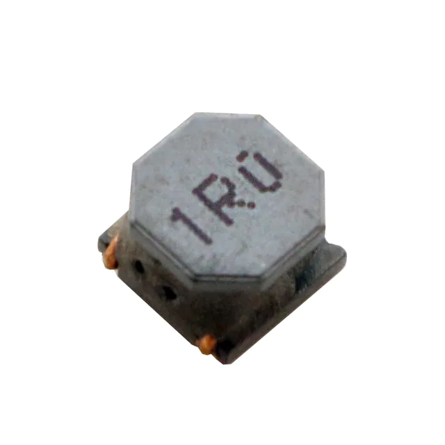
Monolithic Power Systems Inc. MPL-SE4030-150
- Part No.:
- MPL-SE4030-150
- Manufacturer:
- Monolithic Power Systems Inc.
- Category:
- Fixed Inductors
- Package:
- Nonstandard, 2 Lead
- Datasheet:
-
 MPL-SE4030-150.pdf
- Description:
- FIXED IND 15UH 1.6A 185 MOHM SMD
- Quantity:
- Payment:

- Shipping:

Inventory:3,386
Please send an inquiry. Send us your inquiry, and we will respond immediately.
Product details
Overview
MPL-SE4030-150 from Monolithic Power Systems is a semi-shielded power inductor with 15 µH nominal inductance (±20%), 185 mΩ typical DCR, 1.4 A rated current (ΔT = 40 K), and 1.8 A saturation current at 25°C - designed for high-efficiency DC-DC converters in space-constrained embedded computing and battery-powered systems.
For engineers reviewing the MPL-SE4030-150 datasheet, MPL-SE4030-150 pinout (though leadless), MPL-SE4030-150 application in buck converters or input filters, or MPL-SE4030-150 equivalent inductors for thermal or saturation margin trade-offs, this page delivers verified electrical specs, thermal behavior context, and real-world layout-aware performance limits.
Technical Context
This inductor employs a semi-shielded ferrite core construction that balances magnetic shielding and thermal dissipation, enabling low stray field (<10% flux leakage vs. unshielded) while maintaining +125°C max operating temperature including self-heating. Its 4.0 mm × 4.0 mm × 3.0 mm footprint supports high-density PCB layouts.
Inductance is characterized at 100 kHz / 100 mA; saturation threshold is defined by 30% L-drop at both 25°C and 100°C ambient, reflecting derated magnetic performance under thermal stress - critical for sustained load conditions in automotive or industrial SMPS.
Key Specifications
| Parameter | Value and Actual Design Meaning |
|---|---|
| Inductance | 15 µH ±20% at 100 kHz, 100 mA - ensures stable energy storage in 500 kHz–2 MHz buck regulators |
| DC Resistance | 185 mΩ typ / 230 mΩ max - directly impacts conduction loss and thermal rise in continuous conduction mode |
| Rated Current | 1.4 A (ΔT = 40 K on 35 µm Cu, 30×50 mm PCB) - defines safe DC bias limit before thermal throttling |
| Saturation Current | 1.8 A at 25°C, 1.47 A at 100°C - sets peak current headroom before inductance collapse in transient loads |
| Operating Temp | −40°C to +125°C (including self-heating) - validated for under-hood or enclosed industrial environments |
| Resonance Freq | 25 MHz typ - places self-resonance well above typical switching frequencies, preserving inductive behavior |
Pinout & Package
Package: Semi-shielded molded SMD inductor, 4.0 mm × 4.0 mm × 3.0 mm (L×W×H), land pattern per MPS Rev. 1.2 spec - no exposed terminals; solderable bottom electrodes only.
| Pin/Terminal | Circuit Role | Design Meaning |
|---|---|---|
| Bottom Electrode A | Input/Source Connection | Primary current entry point; connects to switch node or input rail in buck topology |
| Bottom Electrode B | Output/Load Connection | Current exit path to output capacitor or load; symmetric layout minimizes loop inductance |
Key Features
| Feature | Design Value |
|---|---|
| Semi-shielded construction | Reduces EMI radiation by >70% vs. unshielded equivalents while allowing higher thermal conductivity than fully shielded types |
| Low DCR (185 mΩ typ) | Enables ≥94% efficiency in 12 V → 3.3 V @ 1.2 A buck designs without forced airflow |
| Low stray magnetic field | Minimizes coupling into adjacent signal traces or sensors - validated via near-field scanning at 1 MHz |
| +125°C max operating temp | Supports operation in sealed enclosures with ambient up to 85°C and 40 K self-rise, meeting IPC-9592 Class 2 requirements |
Applications
| Battery-Powered IoT Node | High-Efficiency SMPS |
|---|---|
Use Scenario: Step-down conversion from single-cell Li-ion (2.7–4.2 V) to 1.8 V core voltage in BLE/Wi-Fi modules. IC Role / Device Role / Timing Role: Energy storage element in synchronous buck regulator IC output stage. Use Value: 1.4 A rated current supports burst transmit currents; 15 µH value optimizes ripple current (≤30%) at 2 MHz switching. | Use Scenario: Main output filter in 24 V → 5 V/3 A industrial DC-DC module with natural convection cooling. IC Role / Device Role / Timing Role: Output choke stabilizing regulated voltage under dynamic load steps up to 2 A/µs. Use Value: 1.8 A ISAT at 25°C prevents inductance collapse during startup surge; semi-shielded design avoids interference with nearby CAN transceivers. |
| Embedded Computing PSU | Input Filter for Motor Drive |
Use Scenario: Point-of-load regulation for FPGA I/O banks requiring low-noise 1.2 V supply in fanless edge server. IC Role / Device Role / Timing Role: Input-side LC filter component attenuating high-frequency switching noise from upstream converter. Use Value: 25 MHz self-resonant frequency ensures pure inductive impedance up to 5 MHz, suppressing harmonics from 1.5 MHz controller. | Use Scenario: EMI suppression on DC bus feeding H-bridge in 24 V brushed DC motor control. IC Role / Device Role / Timing Role: Common-mode choke alternative for differential-mode filtering at motor driver input. Use Value: Low stray field prevents induced noise in encoder feedback lines routed parallel on same PCB layer. |
Availability
MPL-SE4030-150 is available at Aetrix Electronics and suitable for battery-powered IoT nodes, high-efficiency SMPS, and embedded computing power supplies requiring stable component supply across production ramps and long-lifecycle deployments.
Supply support for MPL-SE4030-150 includes scheduled delivery planning, volume procurement assistance, BOM continuity management, traceable sourcing, and lifecycle availability coordination for OEM customers, industrial embedded developers, connected-device designers, and electronics production programs.
Manufacturer
Monolithic Power Systems (MPS) is a fabless semiconductor company specializing in high-performance power management ICs and magnetics, headquartered in Kirkland, WA, with global design and support centers.
The MPL-SE series targets compact, thermally robust DC-DC filtering in space- and efficiency-critical applications - developed specifically for next-generation portable and industrial power systems demanding low-profile magnetics with predictable saturation behavior.
FAQ
What is the recommended PCB land pattern for MPL-SE4030-150?
The official land pattern per Rev. 1.2 datasheet specifies two 3.6 mm × 2.6 mm copper pads spaced 2.4 mm center-to-center, with 0.3 mm solder mask opening clearance. Thermal vias under each pad (minimum 4×0.3 mm) are strongly advised to maintain ΔT ≤ 40 K at full rated current.
How does temperature affect saturation current in this inductor?
Saturation current drops from 1.8 A at 25°C to 1.47 A at 100°C ambient - a 18% reduction - due to ferrite permeability decline with temperature. This derating must be applied when sizing for worst-case thermal environments like sealed enclosures or stacked PCBs.
Can MPL-SE4030-150 replace unshielded inductors in noise-sensitive applications?
Yes - its semi-shielded construction reduces radiated EMI by ≥70% compared to equivalent unshielded inductors, making it suitable for proximity to RF sections or analog sensor circuits where magnetic coupling must be minimized.
Is this inductor RoHS and REACH compliant?
Yes - MPL-SE4030-150 is lead-free, halogen-free, and fully compliant with RoHS Directive 2011/65/EU and REACH Regulation (EC) No. 1907/2006, as confirmed in the MPS Green Status documentation and material declarations.
What is the typical impedance profile across frequency?
Impedance rises linearly from ~1 Ω at 1 MHz to peak at ~25 MHz (25 MHz resonance), then falls as capacitive reactance dominates. At 2 MHz (common buck frequency), impedance is ~12 Ω - sufficient for effective ripple attenuation without excessive AC resistance penalty.
How does DCR tolerance impact thermal design?
DCR maximum is 230 mΩ - 24% higher than typical (185 mΩ). Thermal modeling must use 230 mΩ to ensure worst-case temperature rise stays within the 40 K limit, especially in multi-layer boards with limited copper area.
MPL-SE4030-150 Specifications
- Product attributes
- Attribute value
- Manufacturer:
- Monolithic Power Systems Inc.
- Series:
- MPL-SE
- Package/Case:
- Nonstandard, 2 Lead
- Packaging:
- Tape & Reel (TR)
- Product Status:
- Active
- Type:
- -
- Material - Core:
- -
- Inductance:
- 15 µH
- Tolerance:
- -
- Current Rating (Amps):
- 1.6 A
- Current - Saturation (Isat):
- 1.95A
- Shielding:
- Shielded
- DC Resistance (DCR):
- 185mOhm
- Q @ Freq:
- -
- Frequency - Self Resonant:
- -
- Ratings:
- -
- Operating Temperature:
- -40°C ~ 125°C
- Inductance Frequency - Test:
- 100 kHz
- Features:
- -
- Mounting Type:
- Surface Mount
- Supplier Device Package:
- -
- Size / Dimension:
- 0.157" L x 0.157" W (4.00mm x 4.00mm)
- Height - Seated (Max):
- 0.118" (3.00mm)
MPL-SE4030-150 FAQ
1.How can I place an order for MPL-SE4030-150 through Aetrix?
Please submit a Request for Quotation (RFQ) for MPL-SE4030-150 on Aetrix. Our sales agent will provide a competitive quotation and guide you through the order confirmation once you accept the terms.
2.Are the price and stock information for MPL-SE4030-150 reliable?
The price and inventory of MPL-SE4030-150 are updated periodically and may fluctuate due to market conditions. Stock and pricing data are typically refreshed every 24 hours. Quotation validity for MPL-SE4030-150 is usually 5 days.
3.What payment methods are accepted for MPL-SE4030-150?
We accept Wire Transfer, PayPal, Credit Card, Western Union, MoneyGram, and Escrow for MPL-SE4030-150 transactions.
Note: Certain payment methods may incur a processing fee.
4.How is shipping managed for MPL-SE4030-150?
MPL-SE4030-150 orders can be shipped via leading logistics carriers, including DHL, UPS, FedEx, TNT, or Registered Mail.
Once your MPL-SE4030-150 order is processed, you will receive an email with the shipment details and tracking number.
Note: Tracking information may take up to 24 hours to appear. Express delivery typically takes 3–5 business days.
5.How can I obtain technical support or documentation for MPL-SE4030-150?
For technical support, including MPL-SE4030-150 datasheets, pinout diagrams, or application guidance, please contact our engineering support team. They can provide detailed documentation and assistance for your MPL-SE4030-150 requirements.
6.How does Aetrix verify that MPL-SE4030-150 is sourced from the original manufacturer or authorized distributors?
All MPL-SE4030-150 products on Aetrix are procured from qualified distributors and authorized channels. Our dedicated quality assurance team conducts strict verification, including traceability checks and, if necessary, third-party testing. This ensures that MPL-SE4030-150 meets industry standards.
7.What is the process for return or replacement of MPL-SE4030-150?
All MPL-SE4030-150 units undergo pre-shipment inspection (PSI). If there is an issue with MPL-SE4030-150, returns or replacements are accepted under the following conditions:
1.Quantity discrepancies, incorrect items, or visible external defects (such as breakage or corrosion), acknowledged by Aetrix.
2.The issue is reported within 90 days of delivery.
3.The MPL-SE4030-150 part is unused and in its original packaging.
Return procedure for MPL-SE4030-150:
1.Submit a request within 90 days.
2.Obtain a Return Material Authorization (RMA) from Aetrix.
MPL-SE4030-150 Tags
.jpg)
-
LQP03TN3N3B02D
Murata Electronics

-
LRC0603CS5N6GV001T
Johanson Technology Inc.
-
LRC0402CJ6N8GV001T
Johanson Technology Inc.
-
LRC0402CS3N9GV001T
Johanson Technology Inc.
-
MLG1005S2N2BT000
TDK Corporation
-
LQW15AN2N5C00D
Murata Electronics
.jpg)
-
LQG15HS15NJ02D
Murata Electronics
-
LQG15HS2N7S02D
Murata Electronics
-
LRC0603CJR22GV001T
Johanson Technology Inc.
-
LQG15HS27NJ02D
Murata Electronics
-
LQG15HS6N8J02D
Murata Electronics
-
LQG15HS5N6S02D
Murata Electronics
Tech Hub

Operational amplifier guide covering op amp basics, feedback, ideal vs real op amps, common configurations, buffer circuits, offset, bias current, gain-bandwidth, slew rate, rail-to-rail limits and sel…

Jumper cables guide covering safe connection order, red and black clamp placement, final ground connection, cable gauge, length, clamp quality, copper vs CCA cables, jump starter comparison and battery…

LDO regulator guide covering low dropout voltage, power dissipation, thermal design, PSRR, output noise, capacitor stability, adjustable LDO circuits, LDO vs buck converter and datasheet selection chec…

Conditional Access Module guide covering CAM meaning, CI/CI+ interface, smart card authorization, DVB security workflow, TV and set-top box compatibility, internal electronics, ESD protection, connecto…

Guide to electronic component obsolescence covering EOL risk, PCN/PDN notices, last-time buy planning, replacement options, form-fit-function validation, counterfeit risk and BOM lifecycle management.

18650 battery guide covering lithium-ion cell basics, 3.6V/3.7V voltage, 4.2V charging, mAh and Wh capacity, protected cells, chargers, BMS, series-parallel packs, holders, welding and sourcing checks.…

Hall effect sensor guide covering working principle, linear and digital sensors, Arduino circuits, current sensing, speed detection, automotive applications, A3144 examples, signal filtering and datash…

Product Change Notification guide for electronic components, covering PCN meaning, PCN vs PDN/EOL, common change types, risk levels, form-fit-function review, engineering validation, BOM control, LTB/L…

A practical guide to blend door actuators, covering HVAC function, symptoms, location, AC and heater issues, reset and calibration, replacement cost, electrical diagnosis, compatibility checks, and rep…

Engineering guide to Raspberry Pi alternatives, covering chip-level differences, Orange Pi, ROCK, Jetson, Banana Pi, NanoPi, Compute Module, Pico, GPIO, camera, HAT compatibility, and replacement risks…


