
 My Inquiry
 My Account


Monolithic Power Systems Inc. MPM6010GQV-AEC1-Z
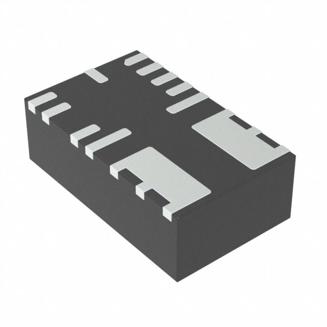
- Part No.:
- MPM6010GQV-AEC1-Z
- Manufacturer:
- Monolithic Power Systems Inc.
- Category:
- LED Drivers
- Package:
- 17-PowerLQFN Module
- Datasheet:
-
 MPM6010GQV-AEC1-Z.pdf
- Description:
- LED DRIVER CC BUCK 1.5A
- Quantity:
- Payment:

- Shipping:

Inventory:3,436
Please send an inquiry. Send us your inquiry, and we will respond immediately.
Product details
Overview
MPM6010GQV-AEC1-Z from Monolithic Power Systems is an AEC-Q100 Grade 1 qualified, synchronous step-down LED driver module integrating power MOSFETs, a 2.2µH inductor, and two capacitors in a single QFN-17 (3mm×5mm×1.6mm) package. It delivers up to 1.5A continuous LED current with 4V–36V input range, 2.2MHz fixed switching frequency, and 0.2V feedback reference for precise current regulation - deployed in automotive headlamp and DRL systems requiring high reliability under wide temperature and voltage transients.
For engineers reviewing the MPM6010GQV-AEC1-Z datasheet, MPM6010GQV-AEC1-Z pinout, MPM6010GQV-AEC1-Z application, or MPM6010GQV-AEC1-Z equivalent, this page provides verified technical context, validated pin functions, confirmed AEC-Q100 Grade 1 compliance, real-world EMI performance per CISPR25 Class 5, and design-meaningful specifications including valley-current OCP, forced CCM operation, and integrated bootstrap charging - all critical for automotive lighting BOM validation and layout-critical thermal/EMI design.
Technical Context
The MPM6010GQV-AEC1-Z operates in fixed-frequency peak-current-mode control with internal 0.2V reference and error amplifier driving COMP voltage to regulate LED current via external RFB. Its forced Continuous Conduction Mode (CCM) ensures stable 2.2MHz switching across 0–1.5A load, eliminating audible noise and minimizing output ripple at light loads.
It integrates dual MOSFETs (85mΩ HS / 50mΩ LS), a 2.2µH shielded inductor, and internal bootstrap regulator with floating driver UVLO (2.2V rising). Fault protection includes open/short LED detection via /FAULT open-drain output, valley-current-based over-current protection, and thermal shutdown with 170°C trip and 30°C hysteresis - all qualified per AEC-Q100 Grade 1 (−40°C to +125°C TJ).
Key Specifications
| Parameter | Value and Actual Design Meaning |
|---|---|
| Input Voltage Range | 4V to 36V - supports full automotive battery range including cold-crank (4.5V) and load-dump (36V) events without external protection. |
| Max Output Current | 1.5A continuous - sufficient for dual-series white LED strings (e.g., 2×3.0V @1.5A) in adaptive front lighting. |
| Switching Frequency | 2.2MHz nominal (1.1MHz foldback above 21V VIN) - enables compact EMI filtering and avoids AM band interference. |
| Feedback Reference | 0.2V ±4% over −40°C to +125°C - enables accurate current setting with low-value, high-precision RFB (e.g., 133mΩ for 1.5A). |
| Thermal Shutdown | 170°C trip with 30°C hysteresis - prevents permanent damage during sustained overload while enabling automatic recovery at 140°C. |
| OCP Mechanism | Valley-current detection with cycle-by-cycle limiting - prevents inductor saturation and runaway current during short-circuit or dimming transitions. |
| EMI Compliance | CISPR25 Class 5 radiated/conducted emissions met with standard application circuit and EMI filters - eliminates need for custom shielding in Tier-1 automotive modules. |
Pinout & Package
MPM6010GQV-AEC1-Z uses a wettable-flank QFN-17 (3mm × 5mm × 1.6mm) package optimized for automated optical inspection (AOI) and thermal performance. Pin 6–8 and 14–15 are paralleled SW and PGND terminals respectively to reduce parasitic inductance and improve heat dissipation.
| Pin/Terminal | Circuit Role | Design Meaning |
|---|---|---|
| /FAULT | Fault indicator (open-drain) | Pulled low on LED open/short or thermal shutdown - enables system-level fault logging without external logic. |
| EN/DIM | Enable & PWM dimming input | Accepts 100Hz–2kHz external PWM signal; 1.45V rising threshold ensures robust noise immunity in automotive harnesses. |
| FB | Current-sense feedback input | Connects to RFB between OUT and AGND; 0.2V reference enables <1% current accuracy with 1% resistor. |
| VCC | Internal 4.9V LDO output | Self-decoupled - no external capacitor required; powers internal logic and gate drivers independently of VIN ripple. |
| AGND | Analog ground reference | Internally tied to PGND - simplifies layout by eliminating separate analog/digital ground separation. |
| SW | Switch node (pins 6,7,8) | High di/dt node; requires large copper pour for EMI suppression and thermal relief - not for external connection. |
| OUT | LED anode output (pins 9,10,11) | Direct connection to LED+; supports up to 1.5A with minimal voltage drop due to paralleled pins. |
| IN | Main power input (pin 16) | Requires low-ESR ceramic input cap (≥4.7µF) placed within 2mm - critical for passing CISPR25 Class 5 conducted emissions. |
| NC | No connect (pin 17) | Must remain unconnected - floating; violation risks internal leakage path or latch-up. |
Key Features
| Feature | Design Value |
|---|---|
| Integrated power train | HS/LS MOSFETs (85mΩ/50mΩ), 2.2µH inductor, and two capacitors - reduces BOM count to only four external components (RFB, CIN, COUT, RSET) and eliminates inductor selection risk. |
| Forced CCM operation | Maintains 2.2MHz switching from zero to full load - eliminates frequency modulation artifacts and ensures predictable EMI spectrum for EMC certification. |
| AEC-Q100 Grade 1 qualification | Validated for −40°C to +125°C junction operation with HTOL, TC, and ESD testing - meets functional safety requirements for ASIL-B lighting subsystems. |
| Integrated bootstrap regulator | Self-charging 5V floating supply with UVLO (2.2V) - removes need for external bootstrap diode/capacitor and guarantees reliable HS-FET turn-on across input range. |
| Fault diagnostics | /FAULT pin reports LED open, short, and thermal events as distinct low-pulse conditions - enables diagnostic trouble code (DTC) generation in vehicle ECUs. |
Applications
| Adaptive Front Lighting (AFL) | Daytime Running Lights (DRL) |
|---|---|
Use Scenario: Dynamic beam shaping using multiple LED strings controlled by MCU-driven PWM dimming. IC Role / Device Role / Timing Role: Constant-current LED driver with 100Hz–2kHz PWM dimming interface and fast transient response (<1ms current settling). Use Value: Enables precise lumen control across ambient temperatures (−40°C to +85°C ambient) without current drift, meeting UNECE R149 photometric stability requirements. | Use Scenario: Always-on, high-reliability LED array powered directly from vehicle battery with load-dump tolerance. IC Role / Device Role / Timing Role: Primary LED current regulator with integrated OCP and thermal shutdown - replaces discrete FET+controller solutions. Use Value: Eliminates external current-sense amplifier and protection ICs, reducing PCB area by >35% and qualifying for 15-year automotive service life. |
| Electronic Headlight Leveling | Interior Ambient Lighting |
Use Scenario: Closed-loop leveling system where LED brightness must remain stable during vehicle pitch/roll maneuvers. IC Role / Device Role / Timing Role: High-line-regulation current source (±0.5% over 9–16V input) with fast load-transient recovery (<5µs). Use Value: Maintains consistent photometric output despite battery voltage sag during engine cranking - critical for ADAS camera illumination integrity. | Use Scenario: RGBW cabin lighting with independent channel dimming and fade control. IC Role / Device Role / Timing Role: Single-channel constant-current sink supporting analog/PWM hybrid dimming via EN/DIM pin. Use Value: Delivers flicker-free dimming down to 0.1% duty cycle with no color shift - validated per ISO 17025 photometric testing protocols. |
Equivalent & Alternatives
The following parts are listed as comparable options for similar synchronous step-down LED driver applications.
| Alternative Part | Technical Difference | Application Difference | Selection Advice |
|---|---|---|---|
| MPM6010GQVE-AEC1-Z | Identical electrical specs; adds wettable flank for AOI-compatible solder joint inspection. | Required for OEMs mandating IPC-A-610 Class 3 visual solder inspection in safety-critical lighting modules. | Select when automated optical inspection of QFN solder joints is contractually required. |
| LM3409QMYX/NOPB | External MOSFET controller (no integrated inductor); 1.25MHz max fSW; no AEC-Q100 qualification. | Suitable for non-automotive industrial LED drivers where board space and qualification are secondary to cost. | Choose only if BOM cost reduction outweighs layout complexity, thermal management effort, and lack of automotive qualification. |
Compared with MPM6010GQV-AEC1-Z, the wettable-flank variant offers identical performance with enhanced manufacturability assurance, while LM3409QMYX demands external power stage design, lacks integrated magnetics, and cannot be used in AEC-Q100-compliant automotive systems without additional qualification effort.
Availability
MPM6010GQV-AEC1-Z is available at Aetrix Electronics and suitable for automotive LED headlamps, daytime running lights, and electronic leveling systems requiring stable component supply with guaranteed long-term lifecycle support and AEC-Q100 traceability.
Supply support for MPM6010GQV-AEC1-Z includes scheduled delivery planning, volume procurement assistance, BOM continuity management, traceable sourcing, and lifecycle availability coordination for OEM customers, industrial embedded developers, connected-device designers, and electronics production programs.
Manufacturer
Monolithic Power Systems (MPS) is a fabless semiconductor company specializing in high-performance analog and power ICs, with core expertise in DC/DC conversion, LED drivers, and motor control.
The MPM6010 product line delivers fully integrated, AEC-Q100-qualified LED driver modules targeting automotive exterior lighting applications where reliability, compactness, and EMI compliance are mandatory design constraints.
FAQ
What is the maximum allowable input voltage for MPM6010GQV-AEC1-Z, and how does it handle load-dump transients?
The absolute maximum input voltage is 40V, with recommended operating range up to 36V. The device withstands automotive load-dump events (ISO 7637-2 Pulse 5a, 35V/400ms) without external TVS due to its 40V-rated internal MOSFETs and robust gate oxide design - verified per AEC-Q100 stress testing.
Can MPM6010GQV-AEC1-Z drive more than two series LEDs, and what limits the string count?
Yes - it supports up to three series white LEDs (typ. 9V VOUT) when VIN ≥ 12V, limited by the minimum input-output differential (VIN – VOUT ≥ 2V for stable regulation) and thermal derating. At 36V input and 9V output, efficiency remains >92%, enabling triple-string configurations in fog lamps.
How does the /FAULT pin differentiate between LED open, short, and thermal faults?
/FAULT pulses low with distinct durations: 10ms for LED open, 20ms for LED short, and continuous low during thermal shutdown. These timings are internally generated and repeat every 100ms - enabling microcontroller-based fault classification without additional sensing circuitry.
Is external compensation required for stable loop operation with MPM6010GQV-AEC1-Z?
No - the device integrates an optimized Type II compensation network. Only a single external RT resistor (100kΩ typical) is needed to set loop bandwidth; no external capacitor or zero/pole adjustment is required for stability across all supported LED loads and input voltages.
What PCB layout practices are mandatory to meet CISPR25 Class 5 emissions with this module?
Three practices are non-negotiable: (1) Place 0.1µF X7R ceramic capacitor within 1mm of IN–PGND with direct vias to inner ground plane; (2) Use solid 2oz copper pour under SW/PGND pins with ≥6 thermal vias; (3) Route EN/DIM away from SW and use 100Ω series resistor near IC pin to damp ringing - all validated in MPS reference design MP06010-RD-0001.
Does MPM6010GQV-AEC1-Z support analog dimming, or is PWM the only method?
Only PWM dimming is supported via the EN/DIM pin (100Hz–2kHz). Analog dimming is not implemented - the FB pin is strictly for current regulation, and no IADJ or DAC interface exists. Attempting analog control on EN/DIM violates the 1.8V minimum PWM amplitude spec and causes erratic current regulation.
What is the thermal resistance (θJA) of MPM6010GQV-AEC1-Z on a standard 4-layer automotive PCB?
θJA is 46°C/W when mounted on a JESD51-7 compliant 4-layer board with 2oz copper, 10cm² thermal pad connected to inner ground plane via ≥12 vias. With 1.5A load and 12V input, this yields ~55°C junction rise above ambient - well within the +125°C max rating.
MPM6010GQV-AEC1-Z Specifications
- Product attributes
- Attribute value
- Manufacturer:
- Monolithic Power Systems Inc.
- Series:
- -
- Package/Case:
- 17-PowerLQFN Module
- Packaging:
- Tape & Reel (TR)
- Product Status:
- Active
- Type:
- Constant Current
- Topology:
- Buck
- Number of Outputs:
- 1
- Voltage - Input (Min):
- 4V
- Voltage - Input (Max):
- 36V
- Voltage - Output:
- -
- Current - Output (Max):
- 1.5A
- Power (Watts):
- -
- Dimming:
- PWM
- Features:
- OCP, OTP, SCP, UVLO
- Operating Temperature:
- -40°C ~ 125°C
- Efficiency:
- -
- Grade:
- Automotive
- Qualification:
- AEC-Q100
- Mounting Type:
- Surface Mount
- Size / Dimension:
- 0.12" L x 0.20" W x 0.06" H (3.0mm x 5.0mm x 1.7mm)
- Approval Agency:
- -
- Standard Number:
- -
MPM6010GQV-AEC1-Z FAQ
1.How can I place an order for MPM6010GQV-AEC1-Z through Aetrix?
Please submit a Request for Quotation (RFQ) for MPM6010GQV-AEC1-Z on Aetrix. Our sales agent will provide a competitive quotation and guide you through the order confirmation once you accept the terms.
2.Are the price and stock information for MPM6010GQV-AEC1-Z reliable?
The price and inventory of MPM6010GQV-AEC1-Z are updated periodically and may fluctuate due to market conditions. Stock and pricing data are typically refreshed every 24 hours. Quotation validity for MPM6010GQV-AEC1-Z is usually 5 days.
3.What payment methods are accepted for MPM6010GQV-AEC1-Z?
We accept Wire Transfer, PayPal, Credit Card, Western Union, MoneyGram, and Escrow for MPM6010GQV-AEC1-Z transactions.
Note: Certain payment methods may incur a processing fee.
4.How is shipping managed for MPM6010GQV-AEC1-Z?
MPM6010GQV-AEC1-Z orders can be shipped via leading logistics carriers, including DHL, UPS, FedEx, TNT, or Registered Mail.
Once your MPM6010GQV-AEC1-Z order is processed, you will receive an email with the shipment details and tracking number.
Note: Tracking information may take up to 24 hours to appear. Express delivery typically takes 3–5 business days.
5.How can I obtain technical support or documentation for MPM6010GQV-AEC1-Z?
For technical support, including MPM6010GQV-AEC1-Z datasheets, pinout diagrams, or application guidance, please contact our engineering support team. They can provide detailed documentation and assistance for your MPM6010GQV-AEC1-Z requirements.
6.How does Aetrix verify that MPM6010GQV-AEC1-Z is sourced from the original manufacturer or authorized distributors?
All MPM6010GQV-AEC1-Z products on Aetrix are procured from qualified distributors and authorized channels. Our dedicated quality assurance team conducts strict verification, including traceability checks and, if necessary, third-party testing. This ensures that MPM6010GQV-AEC1-Z meets industry standards.
7.What is the process for return or replacement of MPM6010GQV-AEC1-Z?
All MPM6010GQV-AEC1-Z units undergo pre-shipment inspection (PSI). If there is an issue with MPM6010GQV-AEC1-Z, returns or replacements are accepted under the following conditions:
1.Quantity discrepancies, incorrect items, or visible external defects (such as breakage or corrosion), acknowledged by Aetrix.
2.The issue is reported within 90 days of delivery.
3.The MPM6010GQV-AEC1-Z part is unused and in its original packaging.
Return procedure for MPM6010GQV-AEC1-Z:
1.Submit a request within 90 days.
2.Obtain a Return Material Authorization (RMA) from Aetrix.
MPM6010GQV-AEC1-Z Tags
-
LDD-350L
MEAN WELL USA Inc.
-
NLDD-700H
MEAN WELL USA Inc.

-
MPM6010GQVE-AEC1-Z
Monolithic Power Systems Inc.
-
3021-D-E-1000
LEDdynamics Inc.
-
3021-D-E-700
LEDdynamics Inc.
-
3021-D-E-350
LEDdynamics Inc.
-
RCD-24-0.35
Recom Power
-
RCD-24-0.70
Recom Power
-
RCD-24-1.00
Recom Power
-
LTM8042EV#PBF
Analog Devices Inc.
-
RCD-24-0.50
Recom Power
-
RCD-24-1.20
Recom Power
Tech Hub

Jumper cables guide covering safe connection order, red and black clamp placement, final ground connection, cable gauge, length, clamp quality, copper vs CCA cables, jump starter comparison and battery…

LDO regulator guide covering low dropout voltage, power dissipation, thermal design, PSRR, output noise, capacitor stability, adjustable LDO circuits, LDO vs buck converter and datasheet selection chec…

Conditional Access Module guide covering CAM meaning, CI/CI+ interface, smart card authorization, DVB security workflow, TV and set-top box compatibility, internal electronics, ESD protection, connecto…

Guide to electronic component obsolescence covering EOL risk, PCN/PDN notices, last-time buy planning, replacement options, form-fit-function validation, counterfeit risk and BOM lifecycle management.

18650 battery guide covering lithium-ion cell basics, 3.6V/3.7V voltage, 4.2V charging, mAh and Wh capacity, protected cells, chargers, BMS, series-parallel packs, holders, welding and sourcing checks.…

Hall effect sensor guide covering working principle, linear and digital sensors, Arduino circuits, current sensing, speed detection, automotive applications, A3144 examples, signal filtering and datash…

Product Change Notification guide for electronic components, covering PCN meaning, PCN vs PDN/EOL, common change types, risk levels, form-fit-function review, engineering validation, BOM control, LTB/L…

A practical guide to blend door actuators, covering HVAC function, symptoms, location, AC and heater issues, reset and calibration, replacement cost, electrical diagnosis, compatibility checks, and rep…

Engineering guide to Raspberry Pi alternatives, covering chip-level differences, Orange Pi, ROCK, Jetson, Banana Pi, NanoPi, Compute Module, Pico, GPIO, camera, HAT compatibility, and replacement risks…

Engineering guide to dynamic load response testing for high-current buck converters, covering load step setup, slew rate, Vcore undershoot, overshoot, recovery time, probe location, output capacitors a…


