
 My Inquiry
 My Account


Monolithic Power Systems Inc. MPQ6527GF-AEC1-P
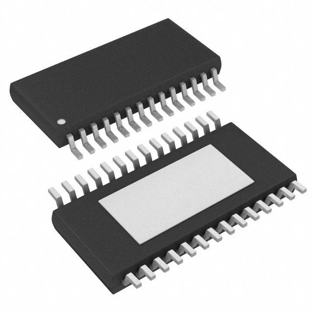
- Part No.:
- MPQ6527GF-AEC1-P
- Manufacturer:
- Monolithic Power Systems Inc.
- Category:
- Motor Drivers, Controllers
- Package:
- 28-TSSOP (0.173", 4.40mm Width) Exposed Pad
- Datasheet:
-
 MPQ6527GF-AEC1-P.pdf
- Description:
- 40V, 0.8A, 10-CHANNEL HALF-BRIDG
- Quantity:
- Payment:

- Shipping:

Inventory:2,500
Please send an inquiry. Send us your inquiry, and we will respond immediately.
Product details
Overview
MPQ6527GF-AEC1-P from Monolithic Power Systems is a 10-channel AEC-Q100 Grade 1 half-bridge motor driver IC with integrated DMOS power MOSFETs, serial SPI control interface, and comprehensive diagnostics. It operates from 5.5V to 40V input, delivers up to 0.8A per channel, features 1.3Ω typical RDS(ON) (HS+LS), and supports automotive body electronics including seat/mirror/window actuators. Its TSSOP-28 EP package enables compact high-channel-count motor control in space-constrained ECUs.
For engineers reviewing the MPQ6527GF-AEC1-P datasheet, MPQ6527GF-AEC1-P pinout, MPQ6527GF-AEC1-P application, or MPQ6527GF-AEC1-P equivalent, key selection criteria include its 10 independent half-bridge topology, AEC-Q100 Grade 1 qualification (-40°C to +125°C TJ), diagnostic coverage (open-load, over-current, thermal pre-warning/shutdown), and 5MHz SPI interface timing compliance with 3.3V/5V logic systems.
Technical Context
The MPQ6527 implements two independent VS supply domains (VS1 for channels 1,2,5,7,8; VS2 for channels 3,4,6,9,10) with internal charge pump and LDO regulation. Each half-bridge is individually configurable via 16-bit SPI frames-separate register sets exist for channels 1–6 and 7–10-with dedicated enable (HBENx), configuration (HBCNFx), and open-load detection enable (OLSD_EN) bits.
Diagnostic architecture includes latched fault reporting per channel (OC, OLD, TW, PSF) on DO output, with thermal pre-warning at 120–140°C and shutdown at 150–175°C, plus UVLO (4.5V threshold) and OVLO (36V threshold) on both VS domains. Serial communication requires CS-active-low framing, DI data sampled on CLK falling edge, and DO output enabled on CS falling edge with PRE_15 bit for thermal shutdown status retention.
Key Specifications
| Parameter | Value and Actual Design Meaning |
|---|---|
| Input Voltage Range | 5.5V to 40V - Supports full automotive battery range including cold-crank (6V) and load-dump (40V) transients without external protection. |
| Output Current per Channel | 0.8A continuous - Sufficient to drive small DC motors, solenoids, and LED arrays in automotive interior modules. |
| RDS(ON) (HS + LS) | 1.3Ω typical - Minimizes conduction loss and self-heating during sustained 0.8A operation at 13.2V supply. |
| SPI Clock Frequency | Up to 5MHz - Enables sub-100μs update of all 10 channels' states, suitable for real-time closed-loop actuator control. |
| Quiescent Current (Standby) | 1–5μA - Allows always-on ECU nodes (e.g., door module) to meet <100μA system sleep budget requirements. |
| Thermal Pre-warning Threshold | 120–140°C - Provides early warning before thermal shutdown, enabling firmware-based derating or fault logging prior to forced output disable. |
| AEC-Q100 Grade | Grade 1 (−40°C to +125°C TJ) - Qualified for under-hood and cabin applications requiring extended temperature reliability. |
Pinout & Package
TSSOP-28 EP package with exposed thermal pad on bottom for enhanced heat dissipation in automotive PCB layouts. Pin count: 28 pins, 4 NC pins, dual VS domain separation, and dedicated TEST pins tied to GND.
| Pin/Terminal | Circuit Role | Design Meaning |
|---|---|---|
| 1, 14, 15, 28 | NC | No connection - Must remain unconnected; no internal function or routing. |
| 2, 13, 16, 27 | GND | Power ground reference - All four pins must be connected to low-impedance PCB ground plane for noise immunity and thermal conduction. |
| 3, 4, 5, 10, 11, 12, 17, 18, 25, 26 | OUT1–OUT10 | Half-bridge outputs - Each drives one motor winding or load; configured independently as HS-on, LS-on, or Hi-Z via SPI. |
| 6 | DI | Serial data input - Accepts 16-bit SPI command frames synchronized to CLK; MSB-first, sampled on CLK falling edge. |
| 7 | VCC | Logic supply - Powers internal digital core and SPI interface; accepts 3.15–5.25V, independent of VS domains. |
| 8 | DO | Serial data output - Returns 16-bit status register (fault flags, channel states) with PRE_15 latched TSD bit. |
| 9 | EN | Enable control - Active-high; pulls low to enter ultra-low-quiescent standby mode (<5μA), resetting SPI registers. |
| 22 | CS | Chip select - Active-low frame delimiter; initiates SPI transaction on falling edge and latches data on rising edge. |
| 23 | CLK | Serial clock - Drives synchronous SPI timing; max 5MHz frequency ensures fast channel reconfiguration. |
| 19, 24 | VS2, VS1 | Power supply inputs - VS1 powers channels 1,2,5,7,8 and internal LDO; VS2 powers channels 3,4,6,9,10; externally tied. |
| 20, 21 | TEST | Factory test pins - Internally connected to production test circuitry; must be tied to GND in application. |
Key Features
| Feature | Design Value |
|---|---|
| Independent 10-channel half-bridge control | Each channel (OUT1–OUT10) configurable via dedicated SPI bits for HS-on, LS-on, or Hi-Z state-enabling bidirectional DC motor control or multi-load switching without external logic. |
| Dual VS supply domains (VS1/VS2) | Allows physical separation of high-noise loads (e.g., window lifters on VS2) from sensitive ones (e.g., mirror adjusters on VS1), reducing crosstalk and improving EMC robustness. |
| Latched diagnostic reporting (OC, OLD, TW, PSF) | Faults persist in status register until cleared by SRR command or EN toggle-enabling host MCU to log failure history and implement fail-safe recovery sequences. |
| Open-load detection with shutdown option | Configurable per group (channels 1–6 or 7–10); when OLSD_EN = 1, detected open-load disables output and latches error-preventing false activation of disconnected actuators. |
| Thermal pre-warning with automatic recovery | At 120–140°C junction, TW bit asserts but outputs remain active; drops automatically below recovery threshold-allowing firmware to reduce duty cycle before shutdown occurs. |
Applications
| Automotive Seat Control | Body Control Module (BCM) |
|---|---|
|
Use Scenario: Driving bidirectional DC motors for power seat fore/aft, recline, and lumbar adjustment in passenger vehicles. IC Role / Device Role / Timing Role: Ten-channel half-bridge driver executing precise PWM-controlled direction and current limiting per motor winding, coordinated via SPI from body controller MCU. Use Value: Eliminates need for ten discrete H-bridges or multiple smaller drivers, reducing BOM count, PCB area, and interconnect complexity while maintaining AEC-Q100 compliance. |
Use Scenario: Controlling door locks, mirror folding, interior lighting, and HVAC dampers in centralized BCM designs. IC Role / Device Role / Timing Role: High-integration load driver managing diverse resistive and inductive loads with unified diagnostics and serial configurability. Use Value: Enables single-chip replacement of multiple legacy drivers, simplifying firmware updates and reducing trace routing congestion on multi-layer automotive PCBs. |
| Automotive Window Lift | Industrial Actuator Control |
|
Use Scenario: Safe, anti-pinch compliant control of front/rear window lift motors using current sensing and thermal monitoring. IC Role / Device Role / Timing Role: Half-bridge driver with integrated SCP, OTP, and open-load detection feeding real-time feedback to MCU for stall detection and force limitation. Use Value: Meets ISO 11452-2/ISO 11452-4 EMC requirements out-of-box and supports functional safety ASIL-B decomposition via diagnostic coverage. |
Use Scenario: Driving stepper motor phases, solenoid valves, or relay coils in factory automation panels and medical equipment. IC Role / Device Role / Timing Role: Robust industrial-grade motor/load driver with wide 5.5–40V input range and -40°C to +125°C operation for harsh environments. Use Value: Reduces design validation effort by leveraging AEC-Q100 qualification as proxy for long-term reliability in non-automotive industrial deployments. |
Equivalent & Alternatives
The following parts are listed as comparable options for similar 10-channel half-bridge driver applications.
| Alternative Part | Technical Difference | Application Difference | Selection Advice |
|---|---|---|---|
| STSPIN250 | 8-channel, 1.3A/channel, 45V max, SPI interface, no dual VS domains | Lacks channel count and separate VS rail support; requires external overvoltage clamping for 40V load-dump | Select when higher per-channel current (1.3A) is prioritized over channel count and automotive-grade diagnostics. |
| TLE9201SG | 8-channel, 0.6A/channel, 40V, LIN interface only, no SPI, no open-load detection | Uses LIN instead of SPI; lacks diagnostic granularity and thermal pre-warning capability | Choose for cost-sensitive LIN-based body nodes where SPI bandwidth and advanced diagnostics are not required. |
Compared with STSPIN250 and TLE9201SG, the MPQ6527GF-AEC1-P uniquely combines 10 independent channels, dual VS domain isolation, SPI-based diagnostics with latched fault reporting, and AEC-Q100 Grade 1 qualification-making it optimal for next-generation automotive ECU consolidation where channel density and diagnostic fidelity are critical.
Availability
MPQ6527GF-AEC1-P is available at Aetrix Electronics and suitable for automotive seat control, body control modules, window lift systems, and industrial actuator applications requiring stable component supply, AEC-Q100 compliance, and long-term lifecycle support.
Supply support for MPQ6527GF-AEC1-P includes scheduled delivery planning, volume procurement assistance, BOM continuity management, traceable sourcing, and lifecycle availability coordination for OEM customers, industrial embedded developers, connected-device designers, and electronics production programs.
Manufacturer
Monolithic Power Systems (MPS) is a fabless semiconductor company specializing in high-performance power management ICs, with design centers in the US, China, and Taiwan, and global manufacturing partnerships.
The MPQ6527 belongs to MPS's automotive-grade motor driver product line, engineered specifically for consolidated body electronics ECUs requiring high channel density, SPI configurability, and comprehensive fault diagnostics under AEC-Q100 stress conditions.
FAQ
What is the maximum allowable junction temperature for continuous operation?
The MPQ6527GF-AEC1-P has a maximum junction temperature of 150°C, with thermal shutdown triggered at 150–175°C. Continuous operation is rated up to 125°C junction temperature per AEC-Q100 Grade 1 specifications; operation beyond this requires derating based on θJA = 32°C/W and ambient conditions.
How does the dual VS domain (VS1/VS2) improve system reliability?
VS1 powers channels 1,2,5,7,8 and internal regulators; VS2 powers channels 3,4,6,9,10. This separation prevents fault propagation-if a short occurs on a VS2-connected load, only those five channels shut down, preserving functionality of VS1-driven actuators like seat position sensors or mirror heaters.
Can the MPQ6527GF-AEC1-P drive stepper motors directly?
No-it provides ten independent half-bridges, not full H-bridge pairs per phase. To drive a 2-phase stepper motor, external external logic or two MPQ6527s would be needed to generate complementary signals; it is optimized for DC motors, solenoids, and generic inductive/resistive loads.
What happens to output states during an over-current event?
When over-current is detected on any channel, the corresponding OC bit latches in the status register, and that half-bridge output is immediately disabled (Hi-Z). The fault remains latched until cleared by Status Register Reset (SRR) command or EN pin toggle-ensuring persistent fault visibility for host MCU diagnostics.
Is the TEST pin required to be connected in production hardware?
Yes-pins 20 and 21 are labeled TEST in the datasheet and must be connected to GND in all production designs. These pins are internally tied to factory test circuitry; leaving them floating may cause undefined behavior or reduced latch-up immunity.
Does the device support daisy-chained SPI configuration?
No-the MPQ6527GF-AEC1-P uses standard 4-wire SPI (DI, DO, CLK, CS) with individual CS lines per device. Daisy-chaining is not supported; each IC requires its own dedicated CS signal from the host MCU to avoid bus contention on the DO line.
What is the purpose of the PRE_15 bit on the DO pin?
PRE_15 is a latched thermal shutdown (TSD) indicator that remains asserted on DO until the first rising CLK edge after CS goes low-even if TSD condition clears-ensuring host MCU reliably captures critical fault events without missing transient shutdown pulses during high-speed SPI polling.
MPQ6527GF-AEC1-P Specifications
- Product attributes
- Attribute value
- Manufacturer:
- Monolithic Power Systems Inc.
- Series:
- -
- Package/Case:
- 28-TSSOP (0.173", 4.40mm Width) Exposed Pad
- Packaging:
- Tape & Reel (TR)
- Product Status:
- Active
- Motor Type - Stepper:
- Bipolar
- Motor Type - AC, DC:
- Brushless DC (BLDC)
- Function:
- Driver - Fully Integrated, Control and Power Stage
- Output Configuration:
- Half Bridge (10)
- Interface:
- SPI
- Technology:
- Power MOSFET
- Step Resolution:
- -
- Applications:
- Industrial
- Current - Output:
- 800mA
- Voltage - Supply:
- 5.5V ~ 40V
- Voltage - Load:
- -
- Operating Temperature:
- -40°C ~ 150°C (TJ)
- Grade:
- Automotive
- Qualification:
- AEC-Q100
- Mounting Type:
- Surface Mount
- Supplier Device Package:
- 28-TSSOP-EP
MPQ6527GF-AEC1-P FAQ
1.How can I place an order for MPQ6527GF-AEC1-P through Aetrix?
Please submit a Request for Quotation (RFQ) for MPQ6527GF-AEC1-P on Aetrix. Our sales agent will provide a competitive quotation and guide you through the order confirmation once you accept the terms.
2.Are the price and stock information for MPQ6527GF-AEC1-P reliable?
The price and inventory of MPQ6527GF-AEC1-P are updated periodically and may fluctuate due to market conditions. Stock and pricing data are typically refreshed every 24 hours. Quotation validity for MPQ6527GF-AEC1-P is usually 5 days.
3.What payment methods are accepted for MPQ6527GF-AEC1-P?
We accept Wire Transfer, PayPal, Credit Card, Western Union, MoneyGram, and Escrow for MPQ6527GF-AEC1-P transactions.
Note: Certain payment methods may incur a processing fee.
4.How is shipping managed for MPQ6527GF-AEC1-P?
MPQ6527GF-AEC1-P orders can be shipped via leading logistics carriers, including DHL, UPS, FedEx, TNT, or Registered Mail.
Once your MPQ6527GF-AEC1-P order is processed, you will receive an email with the shipment details and tracking number.
Note: Tracking information may take up to 24 hours to appear. Express delivery typically takes 3–5 business days.
5.How can I obtain technical support or documentation for MPQ6527GF-AEC1-P?
For technical support, including MPQ6527GF-AEC1-P datasheets, pinout diagrams, or application guidance, please contact our engineering support team. They can provide detailed documentation and assistance for your MPQ6527GF-AEC1-P requirements.
6.How does Aetrix verify that MPQ6527GF-AEC1-P is sourced from the original manufacturer or authorized distributors?
All MPQ6527GF-AEC1-P products on Aetrix are procured from qualified distributors and authorized channels. Our dedicated quality assurance team conducts strict verification, including traceability checks and, if necessary, third-party testing. This ensures that MPQ6527GF-AEC1-P meets industry standards.
7.What is the process for return or replacement of MPQ6527GF-AEC1-P?
All MPQ6527GF-AEC1-P units undergo pre-shipment inspection (PSI). If there is an issue with MPQ6527GF-AEC1-P, returns or replacements are accepted under the following conditions:
1.Quantity discrepancies, incorrect items, or visible external defects (such as breakage or corrosion), acknowledged by Aetrix.
2.The issue is reported within 90 days of delivery.
3.The MPQ6527GF-AEC1-P part is unused and in its original packaging.
Return procedure for MPQ6527GF-AEC1-P:
1.Submit a request within 90 days.
2.Obtain a Return Material Authorization (RMA) from Aetrix.
MPQ6527GF-AEC1-P Tags

-
DRV2603RUNR
Texas Instruments

-
DRV8837CDSGR
Texas Instruments

-
DRV8837DSGR
Texas Instruments
-
DRV8838DSGR
Texas Instruments

-
DRV8839DSSR
Texas Instruments

-
EMC2301-1-ACZL-TR
Microchip Technology
-
DRV8231ADSGR
Texas Instruments

-
EMC2302-2-AIZL-TR
Microchip Technology

-
DRV8800PWPR
Texas Instruments
-
DRV8835DSSR
Texas Instruments

-
EMC2303-1-KP-TR
Microchip Technology

-
DRV8876PWPR
Texas Instruments
Tech Hub

A practical engineering guide to 3.3V and 5V logic compatibility, input thresholds, resistor dividers, translator ICs, MOSFET level shifting, I2C pull-ups, timing limits and power-sequencing risks.

The 74HC595 uses push-pull logic outputs, while the TPIC6B595 uses 50 V open-drain DMOS sinks for higher-power loads. This guide compares timing, current limits, 3.3 V interfacing, load wiring, thermal…

The 74HC595 converts serial data into eight stable parallel outputs. This guide covers pin functions, shift and storage timing, OE and MR behavior, drive-current limits, cascading, voltage compatibilit…

A technical comparison of level-sensitive latches and edge-triggered flip-flops, covering timing windows, setup and hold limits, master–slave operation, time borrowing, race-through, HDL inference and…

A D latch stores one bit while Enable controls when data can pass. This reference covers gate-level operation, truth tables, transparency, setup and hold timing, LE versus OE, common ICs and practical …

An SR latch stores one bit through cross-coupled feedback. This engineering reference covers NOR and NAND implementations, truth tables, forbidden-state recovery, gated operation, switch debouncing, fa…

Latch circuits retain one bit through feedback. This technical reference covers SR and D latches, truth tables, transparency, timing limits, latch-versus-flip-flop behavior, applications and common log…

An engineering guide to LED driver operation, constant-current and constant-voltage outputs, linear and switching topologies, dimming, IC selection, calculations, replacement compatibility, and fault c…

Operational amplifier guide covering op amp basics, feedback, ideal vs real op amps, common configurations, buffer circuits, offset, bias current, gain-bandwidth, slew rate, rail-to-rail limits and sel…

Jumper cables guide covering safe connection order, red and black clamp placement, final ground connection, cable gauge, length, clamp quality, copper vs CCA cables, jump starter comparison and battery…


