
 My Inquiry
 My Account


NXP Semiconductors MPXD2020VLT125
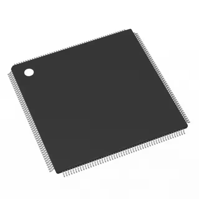
- Part No.:
- MPXD2020VLT125
- Manufacturer:
- NXP Semiconductors
- Category:
- Microcontrollers
- Package:
- 208-LQFP
- Datasheet:
-
 MPXD2020VLT125.pdf
- Description:
- IC MCU 32BIT 2MB FLASH 208TQFP
- Quantity:
- Payment:

- Shipping:

Inventory:2,103
Please send an inquiry. Send us your inquiry, and we will respond immediately.
Product details
Overview
MPXD2020VLT125 from Freescale Semiconductor is a 32-bit Power Architecture® e200z4d microcontroller designed for single-chip industrial HMI systems. It integrates 2 MB ECC flash, 64 KB ECC SRAM, 1 MB non-ECC graphics SRAM, and operates at up to 125 MHz. Its dual display control units (DCU3 and DCULite), OpenVG 1.1 2D graphics accelerator, and VIU2 video input unit enable direct drive of two XGA TFT displays in embedded human-machine interfaces.
For engineers reviewing the MPXD2020VLT125 datasheet, MPXD2020VLT125 pinout, MPXD2020VLT125 application, or MPXD2020VLT125 equivalent, key selection considerations include its 125 MHz FMPLL0 clock, dual-display timing controller (TCON/RSDS), QuadSPI serial flash bandwidth (up to 80 MB/s), low-power STANDBY/STOP modes with sub-millisecond wake-up, and integrated stepper motor control for industrial panel systems.
Technical Context
The MPXD2020VLT125 implements a dual-issue e200z4d core with 4 KB instruction cache, MMU, SPE, and EFP2 floating-point units - enabling deterministic real-time execution of graphics-intensive HMI firmware. Its crossbar switch architecture supports concurrent access by seven masters (CPU, eDMA, DCU3, DCULite, VIU2, GFX2D) to eight slaves including flash, SRAM, graphics SRAM, and QuadSPI.
It features two independent FMPLLs: FMPLL0 delivers the primary 125 MHz system clock, while FMPLL1 supplies modulated/non-modulated clocks to eMIOS, QuadSPI, and pixel timing for DCU/DCULite. The device supports memory-mapped QuadSPI reads with automatic command generation and simultaneous dual-flash access for sustained 80 MB/s bandwidth.
Key Specifications
| Parameter | Value and Actual Design Meaning |
|---|---|
| CPU Core | e200z4d dual-issue Power Architecture core with 4 KB I-cache, MMU, SPE, and EFP2 floating-point unit |
| Max Clock Speed | 125 MHz system frequency via FMPLL0 - enables real-time rendering and multitasking in HMI applications |
| Flash Memory | 2 MB on-chip ECC flash - provides reliable code storage with error correction for industrial field deployments |
| SRAM | 64 KB on-chip ECC SRAM + 1 MB non-ECC graphics SRAM - separates application logic and graphics frame buffers |
| Graphics Acceleration | OpenVG 1.1-compliant 2D GFX2D accelerator - offloads vector graphics rendering from CPU to reduce latency |
| Display Support | DCU3 + DCULite with TCON/RSDS interface - drives two independent color TFT displays up to XGA resolution |
| Video Input | VIU2 supporting ITU-R BT.656 8/10-bit YUV input, de-interlacing, down-scaling, and brightness/contrast adjustment |
| Serial Flash Interface | QuadSPI controller with dual-flash simultaneous read mode - achieves up to 80 MB/s read bandwidth for fast UI asset loading |
Pinout & Package
MPXD2020VLT125 is packaged in a 176-pin LQFP (24 mm × 24 mm, 0.5 mm pitch), optimized for cost-sensitive industrial HMI PCB layouts with accessible routing and thermal management.
| Pin/Terminal | Circuit Role | Design Meaning |
|---|---|---|
| VDD_CORE | Core power supply | 1.2 V regulated input for e200z4d core and internal logic - requires external ballast transistor per on-chip VREG controller |
| VDD_IO | I/O power supply | 3.3 V supply for GPIO, CAN, LIN, SPI, I2C, and ADC - supports mixed-voltage interfacing with peripherals |
| RESET_IN | Asynchronous reset input | Active-low signal initiating full hardware reset - compatible with external supervisor ICs or push-button circuits |
| XTAL_4–16M | Fast external crystal oscillator input | Accepts 4–16 MHz crystal/resonator for FMPLL0 reference - enables precise clock synthesis and EMI control |
| XTAL_32K | Slow external crystal oscillator input | 32 kHz crystal input for RTC autonomous wake-up - supports battery-backed timekeeping and low-power scheduling |
| DCU0_DCLK / DCU1_DCLK | Display pixel clock outputs | Dual independent pixel clocks generated by FMPLL1 - synchronize DCU3 and DCULite to separate display panels |
| VIU2_DATA[7:0] | Parallel video data bus | 8-bit ITU-R BT.656 YUV data path - connects directly to camera modules or video decoders without external FIFO |
| QSPIx_DATA[3:0] | QuadSPI data lines | Four bidirectional IO lines supporting single/dual/quad read modes - enables high-bandwidth serial flash access with minimal pins |
Key Features
| Feature | Design Value |
|---|---|
| Dual Display Control Units | DCU3 and DCULite support simultaneous driving of two independent TFT panels - eliminates need for external display controllers in dual-screen HMIs |
| On-chip Graphics SRAM | 1 MB dedicated two-port graphics SRAM - enables concurrent CPU access and display controller refresh without contention |
| Stepper Motor Control | Integrated SMC supporting six full H-bridge motors with stall detection - reduces BOM count in industrial panel actuators and dial controls |
| Low-Power Wake-up | Sub-24 µs wake-up from STOP mode using 16 MHz IRC - maintains responsiveness in battery-powered or energy-harvested HMI devices |
| Real-Time Video Processing | VIU2 with hardware YUV-to-RGB conversion and de-interlacing - enables live camera feed overlay on TFT displays without CPU load |
| Nexus Class 3+ Debug | IEEE-ISTO 5001-2008 compliant interface with 4×MDO - supports real-time trace, watchpoint triggering, and overrun control for HMI firmware validation |
Applications
| Industrial HMI Panels | Medical Device Displays |
|---|---|
|
Use Scenario: Standalone operator interface for PLC-controlled machinery with touch-enabled TFT screen and status LEDs. IC Role / Device Role / Timing Role: Primary application processor and display driver - executes real-time UI logic, renders OpenVG widgets, and refreshes dual displays at 60 Hz via DCU3/DCULite. Use Value: Eliminates external graphics controller and FPGA, reducing bill-of-materials and board area while maintaining deterministic response under load. |
Use Scenario: Portable diagnostic monitor integrating live ultrasound video overlay and patient parameter visualization. IC Role / Device Role / Timing Role: Video acquisition and display subsystem - captures 8-bit YUV video via VIU2, performs real-time contrast/brightness adjustment, and overlays graphics on XGA display. Use Value: Hardware-accelerated video processing avoids CPU saturation, ensuring stable frame rate and low-latency UI updates during imaging sessions. |
| Automated Test Equipment GUI | Smart Building Control Panel |
|
Use Scenario: Benchtop test instrument with dual-display configuration: one for waveform visualization, another for control menu navigation. IC Role / Device Role / Timing Role: Dual-display timing controller and graphics engine - synchronizes pixel clocks via FMPLL1, manages separate frame buffers in graphics SRAM, and renders vector-based UI elements. Use Value: Independent DCU3/DCULite operation ensures zero frame tearing between displays, critical for accurate waveform interpretation. |
Use Scenario: Wall-mounted HVAC and lighting control panel with ambient light sensing and multi-language UI. IC Role / Device Role / Timing Role: Low-power HMI host - runs from STOP mode between user interactions, wakes on GPIO touch event, and restores UI state from retained 64 KB SRAM. Use Value: Sub-350 µs VREG startup and 8 µs IRC wake-up enable instant UI responsiveness while achieving <10 µA standby current. |
Equivalent & Alternatives
The following parts are listed as comparable options for similar industrial HMI microcontroller applications.
| Alternative Part | Technical Difference | Application Difference | Selection Advice |
|---|---|---|---|
| MPC5604B | Lacks integrated graphics SRAM, OpenVG accelerator, DCU, and VIU2; uses older e200z0 core; max 64 MHz clock | Suitable for non-graphical control tasks only; requires external GPU or FPGA for TFT display support | Select when cost sensitivity outweighs graphics capability and legacy software compatibility is required |
| i.MX RT1064 | ARM Cortex-M7 core; 600 MHz max; includes 1 MB on-chip SRAM but no dedicated graphics SRAM or DCU; relies on external LVDS/TTL display interface | Higher raw CPU performance but no native dual-TFT timing control; requires external display bridge IC for RSDS/TCON | Select when advanced AI inference or Ethernet connectivity is prioritized over integrated display subsystem simplicity |
Compared with MPC5604B and i.MX RT1064, MPXD2020VLT125 uniquely integrates dual-display timing control, OpenVG acceleration, and VIU2 video input in a single die - delivering lower system-level BOM cost and reduced PCB complexity for dedicated industrial HMI designs.
Availability
MPXD2020VLT125 is available at Aetrix Electronics and suitable for industrial HMI panels, medical device displays, automated test equipment GUIs, and smart building control panels requiring stable component supply across long product lifecycles.
Supply support for MPXD2020VLT125 includes scheduled delivery planning, volume procurement assistance, BOM continuity management, traceable sourcing, and lifecycle availability coordination for OEM customers, industrial embedded developers, connected-device designers, and electronics production programs.
Manufacturer
Freescale Semiconductor (now part of NXP Semiconductors) is a fabless semiconductor company specializing in automotive, industrial, and networking processors and analog solutions.
The PX family - including MPXD2020VLT125 - was engineered specifically for cost-effective, graphics-rich industrial human-machine interfaces, emphasizing single-chip integration of display control, video input, and real-time control peripherals.
FAQ
What is the maximum operating frequency of the MPXD2020VLT125?
The MPXD2020VLT125 operates at a maximum system frequency of 125 MHz, delivered by its primary FMPLL0. This clock speed is fully supported across all recommended operating conditions and enables real-time execution of graphics rendering, video processing, and control algorithms within the e200z4d core. The MPXD2020VLT125 datasheet specifies this as a static rating - meaning it is guaranteed under worst-case voltage and temperature conditions.
Does the MPXD2020VLT125 support dual independent TFT displays?
Yes, the MPXD2020VLT125 integrates two display control units: DCU3 and DCULite. Each supports independent timing, resolution (up to XGA), and pixel clock generation - allowing simultaneous drive of two separate TFT panels without external display controllers. The MPXD2020VLT125 also includes a dedicated Timing Controller (TCON) and RSDS interface for DCU3, enabling high-speed differential signaling to large-format displays.
What type of video input does the MPXD2020VLT125 support?
The MPXD2020VLT125 includes a Video Input Unit (VIU2) that accepts 8-bit or 10-bit parallel YUV video data conforming to ITU-R BT.656 standards. It performs hardware-accelerated functions including YUV-to-RGB conversion, de-interlacing, down-scaling, and brightness/contrast adjustment - all without CPU intervention. This makes the MPXD2020VLT125 suitable for integrating live camera feeds directly into HMI displays.
How much on-chip memory does the MPXD2020VLT125 provide?
The MPXD2020VLT125 integrates 2 MB of on-chip ECC flash memory for program storage, 64 KB of on-chip ECC SRAM for application data, and 1 MB of dedicated non-ECC graphics SRAM with a two-port controller. This memory architecture allows concurrent CPU access and display controller refresh - a key differentiator for graphics-intensive HMI applications where memory bandwidth contention must be avoided.
What low-power modes are available on the MPXD2020VLT125?
The MPXD2020VLT125 supports four distinct low-power modes: RUN, HALT, STOP, and STANDBY. STOP mode retains full register and memory state with wake-up in under 350 µs; STANDBY offers lowest power consumption with configurable SRAM retention (64 KB or 8 KB). Both modes support wake-up via GPIO, RTC, or periodic interrupt - making the MPXD2020VLT125 suitable for battery-backed or energy-harvested HMI applications.
MPXD2020VLT125 Specifications
- Product attributes
- Attribute value
- Manufacturer:
- NXP Semiconductors
- Package/Case:
- 208-LQFP
- Series:
- PX
- Packaging:
- Tray
- Product Status:
- Obsolete
- Programmable:
- Not Verified
- Core Processor:
- e200z4d
- Core Size:
- 32-Bit Single-Core
- Speed:
- 125MHz
- Connectivity:
- CANbus, I2C, LINbus, SCI, SPI, UART/USART
- Peripherals:
- DMA, POR, PWM, WDT
- Number of I/O:
- 150
- Program Memory Size:
- 2MB (2M x 8)
- Program Memory Type:
- FLASH
- EEPROM Size:
- -
- RAM Size:
- 64K x 8
- Voltage - Supply (Vcc/Vdd):
- 3V ~ 5.5V
- Data Converters:
- A/D 20x10b
- Oscillator Type:
- Internal
- Operating Temperature:
- -40°C ~ 105°C (TA)
- Grade:
- -
- Qualification:
- -
- Mounting Type:
- Surface Mount
- Supplier Device Package:
MPXD2020VLT125 FAQ
1.How can I place an order for MPXD2020VLT125 through Aetrix?
Please submit a Request for Quotation (RFQ) for MPXD2020VLT125 on Aetrix. Our sales agent will provide a competitive quotation and guide you through the order confirmation once you accept the terms.
2.Are the price and stock information for MPXD2020VLT125 reliable?
The price and inventory of MPXD2020VLT125 are updated periodically and may fluctuate due to market conditions. Stock and pricing data are typically refreshed every 24 hours. Quotation validity for MPXD2020VLT125 is usually 5 days.
3.What payment methods are accepted for MPXD2020VLT125?
We accept Wire Transfer, PayPal, Credit Card, Western Union, MoneyGram, and Escrow for MPXD2020VLT125 transactions.
Note: Certain payment methods may incur a processing fee.
4.How is shipping managed for MPXD2020VLT125?
MPXD2020VLT125 orders can be shipped via leading logistics carriers, including DHL, UPS, FedEx, TNT, or Registered Mail.
Once your MPXD2020VLT125 order is processed, you will receive an email with the shipment details and tracking number.
Note: Tracking information may take up to 24 hours to appear. Express delivery typically takes 3–5 business days.
5.How can I obtain technical support or documentation for MPXD2020VLT125?
For technical support, including MPXD2020VLT125 datasheets, pinout diagrams, or application guidance, please contact our engineering support team. They can provide detailed documentation and assistance for your MPXD2020VLT125 requirements.
6.How does Aetrix verify that MPXD2020VLT125 is sourced from the original manufacturer or authorized distributors?
All MPXD2020VLT125 products on Aetrix are procured from qualified distributors and authorized channels. Our dedicated quality assurance team conducts strict verification, including traceability checks and, if necessary, third-party testing. This ensures that MPXD2020VLT125 meets industry standards.
7.What is the process for return or replacement of MPXD2020VLT125?
All MPXD2020VLT125 units undergo pre-shipment inspection (PSI). If there is an issue with MPXD2020VLT125, returns or replacements are accepted under the following conditions:
1.Quantity discrepancies, incorrect items, or visible external defects (such as breakage or corrosion), acknowledged by Aetrix.
2.The issue is reported within 90 days of delivery.
3.The MPXD2020VLT125 part is unused and in its original packaging.
Return procedure for MPXD2020VLT125:
1.Submit a request within 90 days.
2.Obtain a Return Material Authorization (RMA) from Aetrix.
MPXD2020VLT125 Tags

-
ATTINY4-TSHR
Microchip Technology
-
ATTINY10-TSHR
Microchip Technology
-
ATTINY10-TS8R
Microchip Technology

-
ATTINY202-SSNR
Microchip Technology
-
ATTINY202-SSFR
Microchip Technology
-
ATTINY402-SSNR
Microchip Technology

-
PIC16F15213T-I/MF
Microchip Technology
-
PIC16F15213-E/MF
Microchip Technology

-
PIC10F200T-I/OT
Microchip Technology
-
ATTINY412-SSNR
Microchip Technology
-
PIC10F202T-I/OT
Microchip Technology

-
ATTINY404-SSNR
Microchip Technology
Tech Hub

A practical engineering guide to 3.3V and 5V logic compatibility, input thresholds, resistor dividers, translator ICs, MOSFET level shifting, I2C pull-ups, timing limits and power-sequencing risks.

The 74HC595 uses push-pull logic outputs, while the TPIC6B595 uses 50 V open-drain DMOS sinks for higher-power loads. This guide compares timing, current limits, 3.3 V interfacing, load wiring, thermal…

The 74HC595 converts serial data into eight stable parallel outputs. This guide covers pin functions, shift and storage timing, OE and MR behavior, drive-current limits, cascading, voltage compatibilit…

A technical comparison of level-sensitive latches and edge-triggered flip-flops, covering timing windows, setup and hold limits, master–slave operation, time borrowing, race-through, HDL inference and…

A D latch stores one bit while Enable controls when data can pass. This reference covers gate-level operation, truth tables, transparency, setup and hold timing, LE versus OE, common ICs and practical …

An SR latch stores one bit through cross-coupled feedback. This engineering reference covers NOR and NAND implementations, truth tables, forbidden-state recovery, gated operation, switch debouncing, fa…

Latch circuits retain one bit through feedback. This technical reference covers SR and D latches, truth tables, transparency, timing limits, latch-versus-flip-flop behavior, applications and common log…

An engineering guide to LED driver operation, constant-current and constant-voltage outputs, linear and switching topologies, dimming, IC selection, calculations, replacement compatibility, and fault c…

Operational amplifier guide covering op amp basics, feedback, ideal vs real op amps, common configurations, buffer circuits, offset, bias current, gain-bandwidth, slew rate, rail-to-rail limits and sel…

Jumper cables guide covering safe connection order, red and black clamp placement, final ground connection, cable gauge, length, clamp quality, copper vs CCA cables, jump starter comparison and battery…


