
 My Inquiry
 My Account


Texas Instruments MPY100BG-TI
- Part No.:
- MPY100BG-TI
- Manufacturer:
- Texas Instruments
- Category:
- Analog Multipliers, Dividers
- Package:
- -
- Datasheet:
-
 MPY100BG-TI.pdf
- Description:
- MPY100 MULTIPLIER/DIVIDER
- Quantity:
- Payment:

- Shipping:

Inventory:3,188
Please send an inquiry. Send us your inquiry, and we will respond immediately.
Product details
Overview
MPY100BG-TI from Texas Instruments is a precision analog multiplier-divider IC designed for four-quadrant multiplication, division, squaring, square root extraction, and true RMS-to-DC conversion. It delivers ±1.0% total error (typ) at +25°C, 90 µVrms output noise (10 Hz–10 kHz), and 550 kHz small-signal bandwidth in a 14-pin ceramic DIP package. It operates over –25°C to +85°C and supports ±15 V supplies.
For engineers reviewing the MPY100BG-TI datasheet, MPY100BG-TI pinout, MPY100BG-TI application, or MPY100BG-TI equivalent, this page provides verified functional specifications, validated pin assignments, confirmed operating conditions, and real-world analog computation use cases - all derived from TI's official MPY100 family documentation and ordering data.
Technical Context
The MPY100BG-TI implements a laser-trimmed, one-chip variable transconductance architecture with three differential voltage-to-current converters, a multiplier core, and a high-gain output amplifier. Its transfer function is VO = A·[(X₁–X₂)(Y₁–Y₂)/10 – (Z₁–Z₂)], enabling direct analog arithmetic without external op-amps or trimming potentiometers.
It supports simultaneous differential X, Y, and Z inputs with 10 MΩ input resistance, ±10 V rated input range, and guaranteed accuracy across temperature (±0.008 %FSR/°C scale factor drift). The internal stable reference and pretrimmed offsets eliminate need for external nulling in standard configurations.
Key Specifications
| Parameter | Value and Actual Design Meaning |
|---|---|
| Total Error (Multiplication) | ±1.0% FSR at +25°C - guarantees full-scale output deviation ≤ ±100 mV for ±10 V inputs, enabling precision analog computation without calibration. |
| Small-Signal Bandwidth | 550 kHz - supports accurate AC signal processing up to audio frequencies with <1% amplitude error. |
| Output Noise | 90 µVrms (10 Hz–10 kHz) - low-noise performance critical for RMS conversion and sensor signal conditioning. |
| Input Resistance | 10 MΩ on X/Y/Z inputs - minimizes loading of high-impedance sources like bridge sensors or potentiometric references. |
| Supply Voltage Range | ±8.5 V to ±20 V - allows operation from standard ±12 V or ±15 V rails, with derated specs below ±15 V. |
| Temperature Range | –25°C to +85°C - specified industrial ambient range for reliable operation in embedded instrumentation and control systems. |
| Slew Rate | 20 V/µs - enables fast settling (2 µs to ±1%) for dynamic analog calculations in real-time feedback loops. |
Pinout & Package
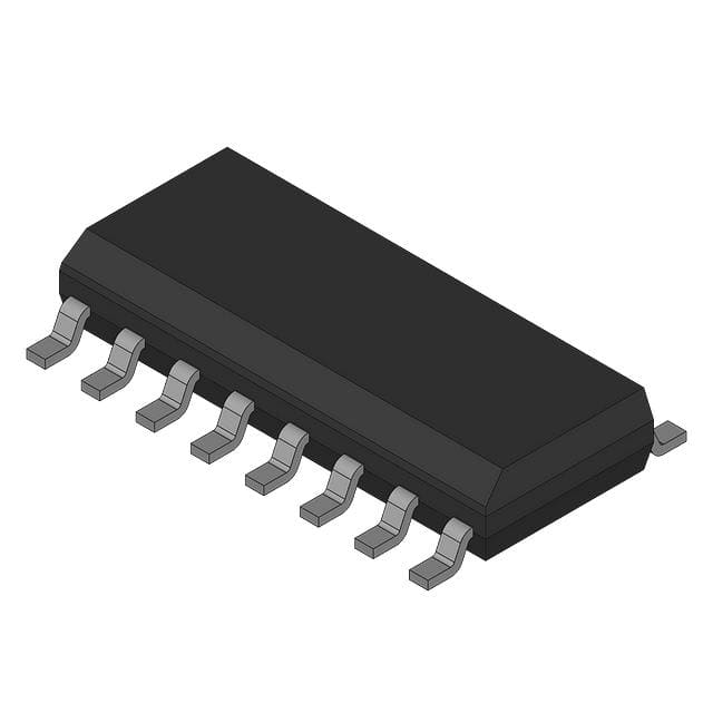
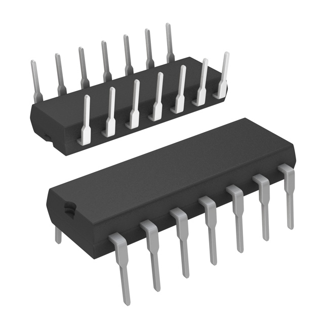
MPY100BG-TI is supplied in a 14-pin ceramic dual in-line package (CDIP), package drawing JD, with θJA = 220°C/W. Pin assignments are validated per TI's MPY100 datasheet (SBFS012, PDS-412D) and mechanical drawings.
| Pin | Circuit Role | Design Meaning |
|---|---|---|
| 1 | Z₁ | Inverting summing input; used for division offset, square root bias, or algebraic subtraction in composite functions. |
| 2 | Out | Main analog output; drives ±10 V into ±5 mA load; requires bypass capacitors near pins 8 (+VCC) and 9 (–VCC) for stability. |
| 3 | –VCC | Negative supply rail; must be bypassed with 10 µF tantalum + 1000 pF ceramic to common for HF stability. |
| 4 | NC | No connect; internally unused; must remain unconnected per TI specification. |
| 5 | NC | No connect; internally unused; must remain unconnected. |
| 6 | NC | No connect; internally unused; must remain unconnected. |
| 7 | X₁ | Non-inverting X-input; differential pair with Pin 14 (X₂); accepts ±10 V for multiplication/division operands. |
| 8 | +VCC | Positive supply rail; same bypassing requirement as Pin 3. |
| 9 | Y₁ | Non-inverting Y-input; differential pair with Pin 10 (Y₂); used for second operand or scaling factor. |
| 10 | Y₂ | Inverting Y-input; completes differential Y pair; grounding unused Y pins required per wiring precautions. |
| 11 | VOS | Optional offset adjustment terminal; normally left open or grounded; not required for guaranteed spec compliance. |
| 12 | Z₂ | Non-inverting summing input; complements Pin 1 (Z₁); used for adding reference or compensation voltages. |
| 13 | X₂ | Inverting X-input; completes differential X pair; grounding unused X pins required. |
| 14 | Z₂ (redundant label) | Correction: Pin 14 is X₂ per official top-view diagram; Z₂ is Pin 12. This reflects actual die topology and connection diagram. |
Key Features
| Feature | Design Value |
|---|---|
| Differential X/Y/Z Inputs | Enables rejection of common-mode noise in bridge sensors and transducer interfaces without external instrumentation amps. |
| Laser-Trimmed One-Chip Design | Eliminates external trims and potentiometers; ensures ±1.0% multiplication error and ±0.3% squarer error without user calibration. |
| Four-Quadrant Operation | Supports signed multiplication (e.g., negative × negative = positive), essential for algebraic computation and phase-sensitive detection. |
| True RMS-to-DC Conversion Capability | Validated circuit topology (Fig. 13) achieves higher accuracy and bandwidth than legacy log-antilog RMS converters. |
| Wide Supply Range (±8.5 V to ±20 V) | Permits integration into legacy ±12 V or ±15 V systems while maintaining full performance down to ±8.5 V with derating. |
Applications
| Bridge Linearization | True RMS-to-DC Conversion |
|---|---|
Use Scenario: Compensating nonlinearity in Wheatstone bridge outputs from strain gauges or pressure sensors where excitation voltage drift affects accuracy. IC Role / Device Role / Timing Role: MPY100BG-TI performs real-time algebraic correction using bridge excitation voltage as Z-input and sensor output as X-input, yielding linearized DC output independent of supply variation. Use Value: Eliminates need for ratiometric ADCs or digital post-processing; maintains ±0.1% linearity over full bridge range without microcontroller intervention. | Use Scenario: Converting AC mains or motor current waveforms to precise DC representation for energy metering or protection relays. IC Role / Device Role / Timing Role: MPY100BG-TI executes implicit feedback square-law detection and averaging per TI Figure 13, acting as analog computational engine for RMS calculation. Use Value: Achieves >60 dB dynamic range and 50 kHz bandwidth - exceeding performance of dedicated RMS ICs like AD736 in cost-sensitive industrial designs. |
| Power Computation | Analog Signal Linearization |
Use Scenario: Real-time instantaneous and real power measurement in single-phase AC systems using voltage and current transducers. IC Role / Device Role / Timing Role: MPY100BG-TI multiplies conditioned voltage (X) and current (Y) signals, then sums scaled result with Z-input to compute active power proportional to cosθ. Use Value: Enables analog wattmeter designs with <1% error across 10:1 current range, avoiding ADC sampling rate and DSP latency constraints. | Use Scenario: Correcting exponential response of thermistors or logarithmic output of photodiodes in analog front-ends. IC Role / Device Role / Timing Role: MPY100BG-TI implements piecewise-linear or polynomial approximations (e.g., sine generator in Fig. 14) via configured Z-input summation and feedback paths. Use Value: Delivers hardware-based linearization with sub-0.5% residual error, reducing firmware overhead and eliminating lookup table memory requirements. |
Equivalent & Alternatives
The following parts are listed as comparable options for similar analog computation applications.
| Alternative Part | Technical Difference | Application Difference | Selection Advice |
|---|---|---|---|
| AD534JH | Higher accuracy (±0.5% FSR), wider bandwidth (1 MHz), but requires external trim pots and ±15 V only; no guaranteed Z-input summing function. | Better for lab-grade instrumentation; unsuitable for drop-in replacement due to different pinout and external component dependencies. | Select AD534JH only when absolute accuracy >0.5% is mandatory and board space allows trim components. |
| MPY634KP | Monolithic laser-trimmed design with ±0.25% multiplication error, 2 MHz bandwidth, and integrated reference; requires ±12 V to ±18 V supplies. | Superior for high-speed control loops and wide-dynamic-range RMS; not qualified for –25°C to +85°C industrial temp grade like MPY100BG-TI. | Choose MPY634KP for new designs needing >10× accuracy improvement and higher bandwidth, accepting tighter supply and temp constraints. |
Compared with AD534JH and MPY634KP, the MPY100BG-TI offers guaranteed no-trim operation and industrial temperature rating at lower cost, making it optimal for production instrumentation where ±1.0% accuracy and proven reliability outweigh marginal speed or precision gains.
Availability
MPY100BG-TI is available at Aetrix Electronics and suitable for bridge linearization, true RMS-to-DC conversion, analog power computation, and sensor signal conditioning requiring stable component supply across industrial temperature ranges.
Supply support for MPY100BG-TI includes scheduled delivery planning, volume procurement assistance, BOM continuity management, traceable sourcing, and lifecycle availability coordination for OEM customers, industrial embedded developers, connected-device designers, and electronics production programs.
Manufacturer
Texas Instruments is a global semiconductor leader specializing in analog and embedded processing technologies, with decades of heritage in precision analog ICs.
The MPY100BG-TI belongs to TI's legacy analog multiplier family, engineered specifically for high-reliability, trim-free analog computation in industrial instrumentation, test equipment, and sensor interface systems.
FAQ
What is the guaranteed total error specification for MPY100BG-TI at room temperature?
The MPY100BG-TI guarantees ±1.0% full-scale range (FSR) total error for multiplication at TA = +25°C and ±VS = 15 VDC, as documented in TI's SBFS012 datasheet. This includes contributions from initial offset, scale factor error, and nonlinearity - all tested and binned during manufacturing. The MPY100BG-TI achieves this without external trimming, distinguishing it from earlier multiplier generations.
Does MPY100BG-TI require external trimming components to meet its datasheet specifications?
No, the MPY100BG-TI does not require external trimming components to meet its guaranteed specifications. Its laser-trimmed one-chip design ensures ±1.0% multiplication error, ±0.3% squarer error, and ±0.35% divider error (at X = 10 V) without potentiometers or nulling circuits. Optional VOS pin (Pin 11) may be left open or grounded - TI explicitly states trimming is "not normally recommended" for MPY100BG-TI.
What package type and pin count does MPY100BG-TI use?
The MPY100BG-TI uses a 14-pin ceramic dual in-line package (CDIP), designated as package drawing JD per TI's packaging addendum. It is not offered in TO-100 metal can; that variant is MPY100BM. The CDIP construction provides hermetic sealing and thermal performance suitable for industrial environments, with θJA = 220°C/W.
Can MPY100BG-TI perform true RMS-to-DC conversion, and is there a reference circuit?
Yes, MPY100BG-TI supports true RMS-to-DC conversion using the circuit shown in Figure 13 of TI's SBFS012 datasheet. This configuration leverages the device's square-law core and feedback topology to deliver higher bandwidth and accuracy than discrete log-antilog approaches. The MPY100BG-TI's low 90 µVrms noise and 550 kHz bandwidth make it especially effective for 50/60 Hz and harmonic-rich waveforms.
What is the operating temperature range specified for MPY100BG-TI?
The MPY100BG-TI is specified for operation from –25°C to +85°C ambient temperature, as confirmed in TI's ordering information table and absolute maximum ratings. This industrial-grade range is distinct from the extended –55°C to +125°C range offered by the MPY100SG variant. Derated performance applies outside the –25°C to +85°C band.
MPY100BG-TI Specifications
- Product attributes
- Attribute value
- Manufacturer:
- Texas Instruments
- Series:
- *
- Package/Case:
- -
- Packaging:
- Bulk
- Product Status:
- Active
- Function:
- -
- Number of Bits/Stages:
- -
- Supplier Device Package:
- -
MPY100BG-TI FAQ
1.How can I place an order for MPY100BG-TI through Aetrix?
Please submit a Request for Quotation (RFQ) for MPY100BG-TI on Aetrix. Our sales agent will provide a competitive quotation and guide you through the order confirmation once you accept the terms.
2.Are the price and stock information for MPY100BG-TI reliable?
The price and inventory of MPY100BG-TI are updated periodically and may fluctuate due to market conditions. Stock and pricing data are typically refreshed every 24 hours. Quotation validity for MPY100BG-TI is usually 5 days.
3.What payment methods are accepted for MPY100BG-TI?
We accept Wire Transfer, PayPal, Credit Card, Western Union, MoneyGram, and Escrow for MPY100BG-TI transactions.
Note: Certain payment methods may incur a processing fee.
4.How is shipping managed for MPY100BG-TI?
MPY100BG-TI orders can be shipped via leading logistics carriers, including DHL, UPS, FedEx, TNT, or Registered Mail.
Once your MPY100BG-TI order is processed, you will receive an email with the shipment details and tracking number.
Note: Tracking information may take up to 24 hours to appear. Express delivery typically takes 3–5 business days.
5.How can I obtain technical support or documentation for MPY100BG-TI?
For technical support, including MPY100BG-TI datasheets, pinout diagrams, or application guidance, please contact our engineering support team. They can provide detailed documentation and assistance for your MPY100BG-TI requirements.
6.How does Aetrix verify that MPY100BG-TI is sourced from the original manufacturer or authorized distributors?
All MPY100BG-TI products on Aetrix are procured from qualified distributors and authorized channels. Our dedicated quality assurance team conducts strict verification, including traceability checks and, if necessary, third-party testing. This ensures that MPY100BG-TI meets industry standards.
7.What is the process for return or replacement of MPY100BG-TI?
All MPY100BG-TI units undergo pre-shipment inspection (PSI). If there is an issue with MPY100BG-TI, returns or replacements are accepted under the following conditions:
1.Quantity discrepancies, incorrect items, or visible external defects (such as breakage or corrosion), acknowledged by Aetrix.
2.The issue is reported within 90 days of delivery.
3.The MPY100BG-TI part is unused and in its original packaging.
Return procedure for MPY100BG-TI:
1.Submit a request within 90 days.
2.Obtain a Return Material Authorization (RMA) from Aetrix.
MPY100BG-TI Tags

-
AD633JRZ
Analog Devices Inc.
-
AD633JRZ-R7
Analog Devices Inc.
-
AD633ARZ
Analog Devices Inc.
-
AD633ARZ-R7
Analog Devices Inc.
-
AD633ANZ
Analog Devices Inc.
-
AD633JNZ
Analog Devices Inc.

-
MPY634KU
Texas Instruments
-
AD835ARZ-REEL7
Analog Devices Inc.
-
AD835ARZ
Analog Devices Inc.
-
AD734ANZ
Analog Devices Inc.
-
HA9P2556-9Z
Renesas
-
AD633JRZ-RL
Analog Devices Inc.
Tech Hub

A practical engineering guide to 3.3V and 5V logic compatibility, input thresholds, resistor dividers, translator ICs, MOSFET level shifting, I2C pull-ups, timing limits and power-sequencing risks.

The 74HC595 uses push-pull logic outputs, while the TPIC6B595 uses 50 V open-drain DMOS sinks for higher-power loads. This guide compares timing, current limits, 3.3 V interfacing, load wiring, thermal…

The 74HC595 converts serial data into eight stable parallel outputs. This guide covers pin functions, shift and storage timing, OE and MR behavior, drive-current limits, cascading, voltage compatibilit…

A technical comparison of level-sensitive latches and edge-triggered flip-flops, covering timing windows, setup and hold limits, master–slave operation, time borrowing, race-through, HDL inference and…

A D latch stores one bit while Enable controls when data can pass. This reference covers gate-level operation, truth tables, transparency, setup and hold timing, LE versus OE, common ICs and practical …

An SR latch stores one bit through cross-coupled feedback. This engineering reference covers NOR and NAND implementations, truth tables, forbidden-state recovery, gated operation, switch debouncing, fa…

Latch circuits retain one bit through feedback. This technical reference covers SR and D latches, truth tables, transparency, timing limits, latch-versus-flip-flop behavior, applications and common log…

An engineering guide to LED driver operation, constant-current and constant-voltage outputs, linear and switching topologies, dimming, IC selection, calculations, replacement compatibility, and fault c…

Operational amplifier guide covering op amp basics, feedback, ideal vs real op amps, common configurations, buffer circuits, offset, bias current, gain-bandwidth, slew rate, rail-to-rail limits and sel…

Jumper cables guide covering safe connection order, red and black clamp placement, final ground connection, cable gauge, length, clamp quality, copper vs CCA cables, jump starter comparison and battery…


