
 My Inquiry
 My Account


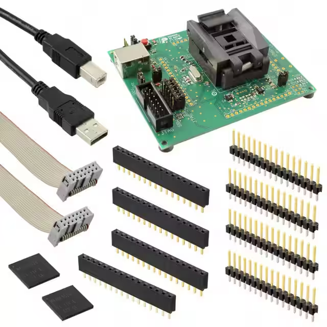
Texas Instruments MSP-TS430RGC64USB
- Part No.:
- MSP-TS430RGC64USB
- Manufacturer:
- Texas Instruments
- Category:
- Programming Adapters, Sockets
- Package:
- Datasheet:
-
 MSP-TS430RGC64USB.pdf
- Description:
- TARGET BOARD ZIF SKT MSP430
- Quantity:
- Payment:

- Shipping:

Inventory:3,903
Please send an inquiry. Send us your inquiry, and we will respond immediately.
Product details
Overview
MSP-TS430RGC64USB from Texas Instruments is a target socket board (TS430) designed for programming, debugging, and in-circuit emulation of MSP430 microcontrollers in 64-pin QFN (RGC) package. It supports JTAG and Spy-Bi-Wire interfaces, delivers full-speed USB 2.0 host connectivity, and enables EnergyTrace™-enabled power profiling for ultra-low-power firmware validation. It is used with Code Composer Studio IDE v10.x for development on MSP430FR5xx/FR6xx, MSP430F5xx/F6xx, and MSP430G2xx families.
For engineers reviewing the MSP-TS430RGC64USB datasheet, MSP-TS430RGC64USB pinout, MSP-TS430RGC64USB application, or MSP-TS430RGC64USB equivalent, this page provides verified mechanical compatibility, interface protocol support, debug feature mapping, and direct integration guidance with TI's MSP430 toolchain - including eZ-FET firmware, CCS v10.x debug server, and EnergyTrace++ mode configuration.
Technical Context
The MSP-TS430RGC64USB implements an eZ-FET-based debug interface compliant with IEEE 1149.1 (JTAG) and SBW (Spy-Bi-Wire) protocols. It integrates a TUSB3410 USB-to-UART bridge IC and onboard voltage regulation (1.8 V / 2.5 V / 3.3 V selectable) to match target MCU I/O voltage levels.
It supports real-time trace via SWO (Serial Wire Output) on compatible MSP430 devices and enables hardware breakpoints, watchpoints, and low-power state entry/exit monitoring via EnergyTrace™ Technology - including LPM3.5/LPM4.5 current measurement resolution down to 10 nA.
Key Specifications
| Parameter | Value and Actual Design Meaning |
|---|---|
| Target Package Support | 64-pin QFN (RGC), 0.5 mm pitch - mechanically aligned socket with zero-insertion-force (ZIF) contact design |
| Debug Interface | JTAG + Spy-Bi-Wire (SBW) - dual-mode auto-detection; no manual switch required |
| Host Interface | USB 2.0 Full-Speed (12 Mbps) - CDC-class enumeration; no driver installation needed on Windows 10/11 |
| Supply Voltage Range | 1.8 V to 3.6 V - user-selectable via DIP switch; matches MSP430 FRAM and Flash device I/O domains |
| EnergyTrace Resolution | 10 nA minimum current measurement - enables accurate LPMx.5 mode validation and battery-life modeling |
| Trace Support | SWO output (4-pin UART-style) - enables real-time printf-style debug logging without halting CPU execution |
Pinout & Package
64-pin QFN (RGC) socket with ZIF contact mechanism; 9 × 9 mm body, 0.5 mm lead pitch, exposed thermal pad. Socket footprint matches TI's MSP430FR6989IRGC64R, MSP430F5529IRGC64R, and MSP430G2955IRGC64R packaging.
| Pin/Terminal | Circuit Role | Design Meaning |
|---|---|---|
| TCK | JTAG Clock Input | Synchronizes debug data transfer between emulator and target; driven by eZ-FET at up to 12 MHz |
| TMS | JTAG Mode Select | Controls JTAG state machine; pulled high internally to enable default debug initialization sequence |
| TDO | JTAG Data Output | Asynchronous serial output from target; supports boundary-scan and register readback |
| TDI | JTAG Data Input | Serial input path for instruction/data loading into target JTAG IR/DR registers |
| RST/NMI | Reset / Non-Maskable Interrupt | Active-low reset assertion; also serves as NMI source during debug halt/resume transitions |
| SBO | Spy-Bi-Wire Output | Bi-directional data line for SBW communication; shared with TDI in SBW mode |
| VCC_TARGET | Target Supply Sense | Monitors target rail voltage for level-shifting and safety cutoff; not a power source |
| GND | Signal Reference | Dedicated low-noise ground plane connection; isolated from USB shield ground to prevent ground loops |
Key Features
| Feature | Design Value |
|---|---|
| Integrated eZ-FET Debug Core | Firmware-upgradable via USB; supports CCS v10.x debug server and TI Cloud Agent for remote debugging |
| Selectable Target I/O Voltage | 1.8 V / 2.5 V / 3.3 V via DIP switch - eliminates external level shifters when interfacing with mixed-voltage MSP430 variants |
| EnergyTrace++ Mode Support | Real-time current/power/energy graphs synchronized with source-level debug session - no external instrumentation required |
| ZIF Socket Mechanical Design | Zero insertion force with spring-loaded pogo pins - prevents solder pad damage during repeated MCU swaps in lab environments |
| SWO Trace Output | 4-pin UART-compatible header - enables non-intrusive runtime logging at up to 1 Mbps without breakpoint overhead |
Applications
| Ultra-Low-Power Sensor Node Development | MSP430FRAM Firmware Validation |
|---|---|
Use Scenario: Rapid prototyping of battery-powered environmental sensors using MSP430FR5969 in LPM3.5 mode. IC Role / Device Role / Timing Role: Debug interface and energy profiler for FRAM-based firmware executing from RAM with periodic wake-up timers. Use Value: Enables sub-μA current measurement accuracy and correlation of code sections (e.g., ADC sampling, FRAM write) with actual energy consumption. |
Use Scenario: Verifying FRAM write endurance and memory protection (MPU/IPE/FRWP) on MSP430FR6989 during secure bootloader development. IC Role / Device Role / Timing Role: In-system debugger providing hardware breakpoints and memory access control verification during secure boot sequence testing. Use Value: Confirms MPU region boundaries and IPE-locked code execution without requiring external logic analyzers or custom test fixtures. |
| MSP430 Migration from IAR to CCS | Production Programming Fixture Interface |
Use Scenario: Porting legacy IAR EW430 projects (v7.x) to CCS v10.x while validating interrupt vector alignment and intrinsic function behavior. IC Role / Device Role / Timing Role: Debug adapter supporting both JTAG and SBW modes to verify vector table placement and C-call convention compliance. Use Value: Eliminates need for separate IAR and CCS debug hardware; validates migration correctness at silicon level before software release. |
Use Scenario: Integration into automated programming stations for MSP430G2553-based consumer electronics manufacturing. IC Role / Device Role / Timing Role: Production-ready socket board enabling batch flash programming and fuse-bit verification via USB command stream. Use Value: Supports >5000 cycles of insert/remove reliability and factory-programmable BSL password access via SBW interface. |
Availability
MSP-TS430RGC64USB is available at Aetrix Electronics and suitable for ultra-low-power sensor node development, MSP430FRAM firmware validation, MSP430 migration from IAR to CCS, production programming fixture interface, and EnergyTrace™-based power optimization requiring stable component supply across industrial, medical, and IoT design cycles.
Supply support for MSP-TS430RGC64USB includes scheduled delivery planning, volume procurement assistance, BOM continuity management, traceable sourcing, and lifecycle availability coordination for OEM customers, industrial embedded developers, connected-device designers, and electronics production programs.
Manufacturer
Texas Instruments is a global semiconductor company headquartered in Dallas, Texas, delivering analog and embedded processing solutions for industrial, automotive, personal electronics, and communications markets.
The MSP-TS430RGC64USB belongs to TI's MSP430 Target Socket Board product line, engineered specifically to accelerate development, debug, and power validation of MSP430 microcontrollers in production-representative QFN packaging.
FAQ
What is the primary function of the MSP-TS430RGC64USB in an MSP430 development workflow?
The MSP-TS430RGC64USB serves as a target socket board that bridges Code Composer Studio IDE to 64-pin QFN-packaged MSP430 MCUs. It provides JTAG/Spy-Bi-Wire debug access, USB-hosted eZ-FET firmware, selectable target voltage, and EnergyTrace™ hardware for real-time power profiling - enabling full-cycle firmware development, low-power validation, and production programming without requiring custom hardware.
Does the MSP-TS430RGC64USB support EnergyTrace++ mode, and what does that enable?
Yes, the MSP-TS430RGC64USB fully supports EnergyTrace++ mode when used with compatible MSP430 devices (e.g., MSP430FR5969, MSP430FR6989) and CCS v10.x. This enables synchronized, source-level correlated views of current, power, and energy consumption - allowing engineers to identify exact lines of code responsible for current spikes, validate LPMx.5 wake-up latency, and quantify energy cost per peripheral operation in μJ units.
Can the MSP-TS430RGC64USB be used with MSP430 devices that have different pin counts or packages?
No - the MSP-TS430RGC64USB is mechanically and electrically optimized exclusively for 64-pin QFN (RGC) MSP430 devices. It does not support TSSOP, SOIC, or other QFN variants (e.g., RHB, RHA). For 40-pin or 80-pin devices, TI offers dedicated socket boards (e.g., MSP-TS430PW28USB, MSP-TS430RHA80USB); mixing packages risks physical damage and signal integrity failure.
How is the target supply voltage configured on the MSP-TS430RGC64USB?
The MSP-TS430RGC64USB uses a 3-position DIP switch (SW1) to select target I/O voltage: position 1 = 1.8 V, position 2 = 2.5 V, position 3 = 3.3 V. This setting controls the level-shifter reference for all debug signals (TCK, TMS, TDI, TDO, RST) and ensures safe interface with MSP430 variants operating across the full 1.8–3.6 V range - including FRAM, Flash, and RF SoC families.
Is the MSP-TS430RGC64USB compatible with Linux or macOS hosts, or only Windows?
The MSP-TS430RGC64USB is supported on Windows, Linux, and macOS hosts when used with Code Composer Studio IDE v10.x. USB CDC-class enumeration works natively on all three platforms. However, EnergyTrace™ hardware features require TI's proprietary drivers and are officially validated only on Windows and select LTS Linux distributions (e.g., Ubuntu 20.04/22.04); macOS support is limited to basic JTAG/SBW debug and flash programming.
MSP-TS430RGC64USB Specifications
- Product attributes
- Attribute value
- Manufacturer:
- Texas Instruments
- Series:
- -
- Packaging:
- Box
- Product Status:
- Obsolete
- Module/Board Type:
- ZIF Socket
- For Use With/Related Products:
- MSP430
MSP-TS430RGC64USB FAQ
1.How can I place an order for MSP-TS430RGC64USB through Aetrix?
Please submit a Request for Quotation (RFQ) for MSP-TS430RGC64USB on Aetrix. Our sales agent will provide a competitive quotation and guide you through the order confirmation once you accept the terms.
2.Are the price and stock information for MSP-TS430RGC64USB reliable?
The price and inventory of MSP-TS430RGC64USB are updated periodically and may fluctuate due to market conditions. Stock and pricing data are typically refreshed every 24 hours. Quotation validity for MSP-TS430RGC64USB is usually 5 days.
3.What payment methods are accepted for MSP-TS430RGC64USB?
We accept Wire Transfer, PayPal, Credit Card, Western Union, MoneyGram, and Escrow for MSP-TS430RGC64USB transactions.
Note: Certain payment methods may incur a processing fee.
4.How is shipping managed for MSP-TS430RGC64USB?
MSP-TS430RGC64USB orders can be shipped via leading logistics carriers, including DHL, UPS, FedEx, TNT, or Registered Mail.
Once your MSP-TS430RGC64USB order is processed, you will receive an email with the shipment details and tracking number.
Note: Tracking information may take up to 24 hours to appear. Express delivery typically takes 3–5 business days.
5.How can I obtain technical support or documentation for MSP-TS430RGC64USB?
For technical support, including MSP-TS430RGC64USB datasheets, pinout diagrams, or application guidance, please contact our engineering support team. They can provide detailed documentation and assistance for your MSP-TS430RGC64USB requirements.
6.How does Aetrix verify that MSP-TS430RGC64USB is sourced from the original manufacturer or authorized distributors?
All MSP-TS430RGC64USB products on Aetrix are procured from qualified distributors and authorized channels. Our dedicated quality assurance team conducts strict verification, including traceability checks and, if necessary, third-party testing. This ensures that MSP-TS430RGC64USB meets industry standards.
7.What is the process for return or replacement of MSP-TS430RGC64USB?
All MSP-TS430RGC64USB units undergo pre-shipment inspection (PSI). If there is an issue with MSP-TS430RGC64USB, returns or replacements are accepted under the following conditions:
1.Quantity discrepancies, incorrect items, or visible external defects (such as breakage or corrosion), acknowledged by Aetrix.
2.The issue is reported within 90 days of delivery.
3.The MSP-TS430RGC64USB part is unused and in its original packaging.
Return procedure for MSP-TS430RGC64USB:
1.Submit a request within 90 days.
2.Obtain a Return Material Authorization (RMA) from Aetrix.
MSP-TS430RGC64USB Tags
-
AC102015
Microchip Technology
-
LGA SOCKET SML
Telit Cinterion
-
SI5332-32SKT-DK
Skyworks Solutions Inc.
-
SI5332-40SKT-DK
Skyworks Solutions Inc.
-
SI538X4X-64SKT-DK
Skyworks Solutions Inc.
-
PA-SOD6SM18-28
Logical Systems Inc.
-
SI538X4X-44SKT-DK
Skyworks Solutions Inc.

-
SLG47528V-SKT
Renesas Electronics Operations Services Limited
-
SLG47525V-SKT
Renesas Electronics Operations Services Limited
-
LSOCTS08EA-1
BPM Microsystems
-
ATSTK600-UC3A0X-144
Microchip Technology
-
LSOCS08EA-1
BPM Microsystems
Tech Hub

A practical engineering guide to 3.3V and 5V logic compatibility, input thresholds, resistor dividers, translator ICs, MOSFET level shifting, I2C pull-ups, timing limits and power-sequencing risks.

The 74HC595 uses push-pull logic outputs, while the TPIC6B595 uses 50 V open-drain DMOS sinks for higher-power loads. This guide compares timing, current limits, 3.3 V interfacing, load wiring, thermal…

The 74HC595 converts serial data into eight stable parallel outputs. This guide covers pin functions, shift and storage timing, OE and MR behavior, drive-current limits, cascading, voltage compatibilit…

A technical comparison of level-sensitive latches and edge-triggered flip-flops, covering timing windows, setup and hold limits, master–slave operation, time borrowing, race-through, HDL inference and…

A D latch stores one bit while Enable controls when data can pass. This reference covers gate-level operation, truth tables, transparency, setup and hold timing, LE versus OE, common ICs and practical …

An SR latch stores one bit through cross-coupled feedback. This engineering reference covers NOR and NAND implementations, truth tables, forbidden-state recovery, gated operation, switch debouncing, fa…

Latch circuits retain one bit through feedback. This technical reference covers SR and D latches, truth tables, transparency, timing limits, latch-versus-flip-flop behavior, applications and common log…

An engineering guide to LED driver operation, constant-current and constant-voltage outputs, linear and switching topologies, dimming, IC selection, calculations, replacement compatibility, and fault c…

Operational amplifier guide covering op amp basics, feedback, ideal vs real op amps, common configurations, buffer circuits, offset, bias current, gain-bandwidth, slew rate, rail-to-rail limits and sel…

Jumper cables guide covering safe connection order, red and black clamp placement, final ground connection, cable gauge, length, clamp quality, copper vs CCA cables, jump starter comparison and battery…


