
 My Inquiry
 My Account


Microchip Technology MT90820AL1
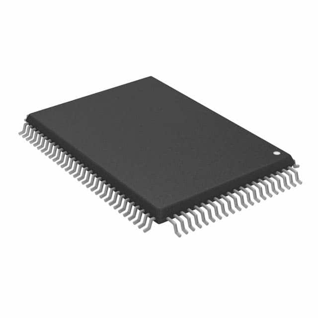
- Part No.:
- MT90820AL1
- Manufacturer:
- Microchip Technology
- Category:
- Telecom
- Package:
- 100-BQFP
- Datasheet:
-
 MT90820AL1.pdf
- Description:
- IC TELECOM INTERFACE 100MQFP
- Quantity:
- Payment:

- Shipping:

Inventory:3,554
Please send an inquiry. Send us your inquiry, and we will respond immediately.
Product details
Overview
MT90820AL1 from Zarlink Semiconductor is a 2,048 × 2,048 non-blocking digital switch IC for ST-BUS/GCI time-division multiplexing systems, operating at up to 8.192 Mb/s serial data rate with per-channel variable or constant throughput delay, IEEE-1149.1 JTAG test support, and 100-pin MQFP packaging. It serves as a large-scale TDM crosspoint switch in voice/data multiplexers and digital cross-connect systems.
For engineers reviewing the MT90820AL1 datasheet, MT90820AL1 pinout, MT90820AL1 application, or MT90820AL1 equivalent, key selection considerations include its 16-input/16-output ST-BUS interface, frame offset calibration capability, per-channel high-impedance control, Motorola-compatible microprocessor bus interface, and WFP/ST-BUS mode switching via WFPS pin.
Technical Context
The MT90820AL1 implements a fully programmable TDM switch fabric with dual-mode serial interface timing (ST-BUS/GCI or Wide Frame Pulse), supporting 2.048/4.096/8.192 Mb/s data rates and corresponding master clock frequencies of 4.096/8.192/16.384 MHz. Its internal architecture includes serial-to-parallel and parallel-to-serial converters, 2,048-byte data memory, and connection memory with per-channel message/connection mode selection.
It features per-stream frame delay offset programming, automatic ST-BUS/GCI format identification, input frame offset measurement via FE/HCLK, and loopback control per channel via LPBK bit. The device supports both multiplexed and Motorola non-multiplexed CPU interfaces selected by IM pin, with full JTAG boundary scan compliance via TCK/TDO/TDI/TRST/TMS pins.
Key Specifications
| Parameter | Value and Actual Design Meaning |
|---|---|
| Switch Capacity | 2,048 × 2,048 channels at 8.192 Mb/s; scales to 1,024 × 1,024 at 4.096 Mb/s and 512 × 512 at 2.048 Mb/s - defines maximum simultaneous PCM/time-slot connections without blocking. |
| Serial Data Rate | 2.048 / 4.096 / 8.192 Mb/s - determines number of 64 kbit/s channels per stream (32/64/128) and required CLK frequency (4.096/8.192/16.384 MHz). |
| Throughput Delay Mode | Per-channel selectable variable (min. 3 time-slots) or constant (min. 1 frame) delay - enables optimization for voice (low latency) or data (frame integrity) applications. |
| Frame Alignment | Automatic ST-BUS/GCI detection + manual WFP mode via WFPS pin - ensures compatibility with telecom framing standards without external logic. |
| Microprocessor Interface | Motorola non-multiplexed or multiplexed bus support via IM pin - allows direct connection to MC68K-family or standard 8080-style controllers without glue logic. |
| JTAG Support | IEEE-1149.1 compliant test port (TCK/TDO/TDI/TRST/TMS) - enables boundary-scan testing and in-system programming verification. |
| Operating Temperature | –40°C to +85°C - qualified for industrial and telecom infrastructure environments including central office and remote terminal equipment. |
Pinout & Package
MT90820AL1 is housed in a 100-pin MQFP (Metric Quad Flat Package) with 0.5 mm lead pitch, RoHS-compliant matte tin finish, and thermal pad exposed on underside for enhanced heat dissipation in high-density telecom PCBs.
| Pin | Circuit Role | Design Meaning |
|---|---|---|
| STi0–STi15 | ST-BUS Input Streams | 16 bidirectional serial inputs accepting 2.048/4.096/8.192 Mb/s streams; each mapped to 32/64/128 time-slots per 125 µs frame. |
| STo0–STo15 | ST-BUS Output Streams | 16 three-state serial outputs with per-channel high-impedance control via ODE pin and connection memory OE bits. |
| F0i | Frame Pulse Input | Accepts 8 kHz frame sync signal; automatically detects ST-BUS (falling-edge aligned) or GCI (rising-edge aligned) format when WFPS = 0. |
| FE/HCLK | Frame Evaluation / Clock Input | In ST-BUS mode: measures input frame offset vs F0i; in WFP mode: provides 4.096 MHz HCLK for frame alignment timing. |
| CLK | Master Serial Clock | Input clock at 4.096/8.192/16.384 MHz - must be exactly 2× selected serial data rate for proper bit sampling and parallel conversion. |
| ODE | Output Drive Enable | Global enable for STo0–STo15 drivers; overrides per-channel tristate control when low, placing all outputs in high-Z state. |
| WFPS | Wide Frame Pulse Select | When high: enables WFP mode requiring 16.384 MHz CLK and 4.096 MHz HCLK; when low: enables auto-detect ST-BUS/GCI mode. |
| IM | CPU Interface Mode | When low: configures microport for Motorola non-multiplexed bus (A0–A7, AD0–AD7/D8–D15); when high: enables multiplexed mode. |
| TCK–TDO | JTAG Test Port | Full IEEE-1149.1 boundary scan interface - supports production test, debug, and in-field diagnostics without dedicated test hardware. |
Key Features
| Feature | Design Value |
|---|---|
| Per-channel message mode | Enables microprocessor to write custom 8-bit data directly to connection memory for broadcast control/status messages on any output channel. |
| Automatic ST-BUS/GCI identification | Eliminates external framing logic by detecting input frame polarity and aligning internal timing without software configuration. |
| Per-stream frame delay offset programming | Compensates for variable backplane path delays across multi-chip switch fabrics by calibrating individual STi0–STi15 input alignment. |
| Memory block programming | Initializes all 2,048 connection memory locations in two frames using IMS register pattern - reduces boot-time configuration overhead. |
| Internal per-channel loopback | Allows diagnostic verification of ST-BUS output-to-input data path without external cabling, controlled via LPBK bit in connection memory. |
Applications
| Medium-Scale Digital Cross-Connect | Voice/Data Multiplexer |
|---|---|
Use Scenario: Central office node aggregating E1/T1 lines into higher-order DS3 or STM-1 transport paths. IC Role / Device Role / Timing Role: TDM time-slot interchange switch performing non-blocking 64 kbit/s channel routing between 16 input and 16 output ST-BUS streams. Use Value: Supports dynamic reconfiguration of voice circuits and data channels via microprocessor-controlled connection memory writes, enabling service provisioning without hardware changes. |
Use Scenario: Enterprise PBX or IP gateway combining analog voice ports and Ethernet data onto shared E1 infrastructure. IC Role / Device Role / Timing Role: Time-division multiplexer integrating PCM voice samples and packetized data into synchronized ST-BUS frames with frame-integrity-preserving constant delay mode. Use Value: Maintains strict 125 µs frame boundaries for voice while allowing bursty data insertion via message mode, eliminating inter-frame jitter in mixed-traffic links. |
| CTI Application Platform | IEEE 802.9a Compliant Media Gateway |
Use Scenario: Computer-Telephony Integration system linking CTI servers to multiple PSTN line cards for call control and recording. IC Role / Device Role / Timing Role: Low-latency TDM switch providing sub-frame (<3 time-slot) variable delay routing for real-time signaling and audio monitoring paths. Use Value: Enables precise synchronization between host processor interrupts and voice channel activity via per-channel delay tuning and frame offset calibration. |
Use Scenario: Converged media gateway implementing IEEE 802.9a isochronous LAN-to-PSTN bridging with guaranteed timing accuracy. IC Role / Device Role / Timing Role: ST-BUS interface controller ensuring deterministic 8 kHz frame alignment between LAN-side timestamping and PSTN-side PCM sampling. Use Value: Achieves <±1 µs frame edge jitter via automatic ST-BUS/GCI detection and FE-based offset compensation, meeting 802.9a Class A timing requirements. |
Equivalent & Alternatives
The following parts are listed as comparable options for similar TDM switching applications.
| Alternative Part | Technical Difference | Application Difference | Selection Advice |
|---|---|---|---|
| ZL50012 | Single-chip 512×512 TDM switch with integrated PLL and 3.3 V operation; lacks WFP mode and per-stream frame offset registers. | Targeted at compact access nodes and VoIP gateways where full 2k×2k capacity and telecom-grade frame calibration are not required. | Choose ZL50012 for lower power, smaller footprint, and simplified clocking - but only if 512×512 capacity and absence of WFP mode are acceptable. |
| MT90782 | Legacy 1,024×1,024 ST-BUS switch with identical 100-pin MQFP package and Motorola bus interface, but no JTAG or message mode support. | Suitable for cost-sensitive upgrades of existing MT90782-based designs where new features like loopback or frame offset calibration are not needed. | Choose MT90782 only for drop-in replacement in legacy systems - MT90820AL1 adds critical diagnostics and calibration capabilities absent in MT90782. |
Compared with ZL50012 and MT90782, the MT90820AL1 uniquely delivers full 2,048×2,048 non-blocking capacity with per-stream frame offset calibration, WFP/ST-BUS dual-mode operation, and IEEE-1149.1 JTAG - making it the only option for carrier-class digital cross-connects requiring field-traceable timing alignment and multi-chip synchronization.
Availability
MT90820AL1 is available at Aetrix Electronics and suitable for medium/large switching platforms, CTI application infrastructure, and IEEE 802.9a media gateways requiring stable component supply across extended product lifecycles.
Supply support for MT90820AL1 includes scheduled delivery planning, volume procurement assistance, BOM continuity management, traceable sourcing, and lifecycle availability coordination for OEM customers, industrial embedded developers, connected-device designers, and electronics production programs.
Manufacturer
Zarlink Semiconductor was a fabless semiconductor company specializing in timing, voice, and network interface ICs for telecommunications infrastructure, acquired by Microsemi in 2011.
The MT90820AL1 belongs to Zarlink's CMOS ST-BUS™ Family of large digital switches, designed specifically for carrier-grade TDM cross-connect and voice/data multiplexing applications requiring deterministic frame alignment and scalable channel density.
FAQ
What is the maximum serial data rate supported by the MT90820AL1?
The MT90820AL1 supports a maximum serial data rate of 8.192 Mb/s, enabling 2,048 × 2,048 non-blocking channel switching with 128 time-slots per 125 µs frame. At this rate, the required master clock (CLK) is 16.384 MHz, and the device operates in 8 Mb/s serial link mode as defined in Table 1 of the datasheet. This rate is confirmed for the MT90820AL1 variant in the Ordering Information section.
Does the MT90820AL1 support both ST-BUS and GCI interface standards?
Yes, the MT90820AL1 automatically identifies and adapts to either ST-BUS or GCI framing formats when the WFPS pin is low. In ST-BUS mode, it detects falling-edge-aligned 8 kHz frame pulses; in GCI mode, it detects rising-edge-aligned pulses - all without software configuration. This dual-standard support is explicitly documented in the Features and Functional Description sections of the datasheet.
How does the frame offset calibration function work on the MT90820AL1?
The MT90820AL1 uses the FE/HCLK pin to measure input frame offset relative to F0i, storing results in the Frame Alignment Register (FAR). Each STi0–STi15 stream can then be individually delayed by up to +4 CLK periods in ½-clock increments via Frame Input Offset (FOR) registers. This compensates for variable backplane propagation delays in multi-chip switch fabrics, as detailed in the Input Frame Offset Selection section.
What is the purpose of the CSTo pin on the MT90820AL1?
The CSTo pin on the MT90820AL1 outputs a 4.096/8.192/16.384 Mb/s control stream derived from the CSTo bit in connection memory - one bit per channel, transmitted one time-slot ahead of the associated ST-BUS output. It carries 512/1,024/2,048 bits per frame and is used for external circuit control, status signaling, or synchronization with downstream devices, as specified in the Pin Description and Connection Memory Control sections.
Can the MT90820AL1 operate with a 3.3 V supply?
No, the MT90820AL1 requires a +5 V power supply (VDD) as confirmed by the Pin Description table listing pin 2/32/63 and 5/40/67 as "+5 Volt Power Supply" and the Absolute Maximum Ratings section specifying VDD = 5.5 V max. It is not 3.3 V compatible, and operation outside the 4.75–5.25 V range may cause functional failure or damage.
MT90820AL1 Specifications
- Product attributes
- Attribute value
- Manufacturer:
- Microchip Technology
- Series:
- -
- Package/Case:
- 100-BQFP
- Packaging:
- Tray
- Product Status:
- Obsolete
- Function:
- Switch
- Interface:
- -
- Number of Circuits:
- 1
- Voltage - Supply:
- 4.75V ~ 5.25V
- Current - Supply:
- 170mA
- Power (Watts):
- -
- Operating Temperature:
- -40°C ~ 85°C
- Grade:
- -
- Qualification:
- -
- Mounting Type:
- Surface Mount
- Supplier Device Package:
- 100-MQFP (14x20)
MT90820AL1 FAQ
1.How can I place an order for MT90820AL1 through Aetrix?
Please submit a Request for Quotation (RFQ) for MT90820AL1 on Aetrix. Our sales agent will provide a competitive quotation and guide you through the order confirmation once you accept the terms.
2.Are the price and stock information for MT90820AL1 reliable?
The price and inventory of MT90820AL1 are updated periodically and may fluctuate due to market conditions. Stock and pricing data are typically refreshed every 24 hours. Quotation validity for MT90820AL1 is usually 5 days.
3.What payment methods are accepted for MT90820AL1?
We accept Wire Transfer, PayPal, Credit Card, Western Union, MoneyGram, and Escrow for MT90820AL1 transactions.
Note: Certain payment methods may incur a processing fee.
4.How is shipping managed for MT90820AL1?
MT90820AL1 orders can be shipped via leading logistics carriers, including DHL, UPS, FedEx, TNT, or Registered Mail.
Once your MT90820AL1 order is processed, you will receive an email with the shipment details and tracking number.
Note: Tracking information may take up to 24 hours to appear. Express delivery typically takes 3–5 business days.
5.How can I obtain technical support or documentation for MT90820AL1?
For technical support, including MT90820AL1 datasheets, pinout diagrams, or application guidance, please contact our engineering support team. They can provide detailed documentation and assistance for your MT90820AL1 requirements.
6.How does Aetrix verify that MT90820AL1 is sourced from the original manufacturer or authorized distributors?
All MT90820AL1 products on Aetrix are procured from qualified distributors and authorized channels. Our dedicated quality assurance team conducts strict verification, including traceability checks and, if necessary, third-party testing. This ensures that MT90820AL1 meets industry standards.
7.What is the process for return or replacement of MT90820AL1?
All MT90820AL1 units undergo pre-shipment inspection (PSI). If there is an issue with MT90820AL1, returns or replacements are accepted under the following conditions:
1.Quantity discrepancies, incorrect items, or visible external defects (such as breakage or corrosion), acknowledged by Aetrix.
2.The issue is reported within 90 days of delivery.
3.The MT90820AL1 part is unused and in its original packaging.
Return procedure for MT90820AL1:
1.Submit a request within 90 days.
2.Obtain a Return Material Authorization (RMA) from Aetrix.
MT90820AL1 Tags

-
LMC567CMX/NOPB
Texas Instruments
-
LM567CMX/NOPB
Texas Instruments
-
LM567CM/NOPB
Texas Instruments

-
VSC8531XMW-02
Microchip Technology
-
VSC8531XMW-05
Microchip Technology

-
GPY115C0VI
MaxLinear, Inc.

-
SI32185-A-FMR
Skyworks Solutions Inc.

-
VSC8541XMV-05
Microchip Technology

-
SI32178-B-FM1R
Skyworks Solutions Inc.
-
GPY215C0VI
MaxLinear, Inc.

-
CPC7514ZTR
Littelfuse Inc.

-
VSC8502XML-03
Microchip Technology
Tech Hub

TTL and CMOS logic families differ in thresholds, loading, output drive, power and timing. This engineering guide compares 74HC and 74HCT, calculates noise margins and checks 3.3 V/5 V compatibility.

A practical engineering guide to 3.3V and 5V logic compatibility, input thresholds, resistor dividers, translator ICs, MOSFET level shifting, I2C pull-ups, timing limits and power-sequencing risks.

The 74HC595 uses push-pull logic outputs, while the TPIC6B595 uses 50 V open-drain DMOS sinks for higher-power loads. This guide compares timing, current limits, 3.3 V interfacing, load wiring, thermal…

The 74HC595 converts serial data into eight stable parallel outputs. This guide covers pin functions, shift and storage timing, OE and MR behavior, drive-current limits, cascading, voltage compatibilit…

A technical comparison of level-sensitive latches and edge-triggered flip-flops, covering timing windows, setup and hold limits, master–slave operation, time borrowing, race-through, HDL inference and…

A D latch stores one bit while Enable controls when data can pass. This reference covers gate-level operation, truth tables, transparency, setup and hold timing, LE versus OE, common ICs and practical …

An SR latch stores one bit through cross-coupled feedback. This engineering reference covers NOR and NAND implementations, truth tables, forbidden-state recovery, gated operation, switch debouncing, fa…

Latch circuits retain one bit through feedback. This technical reference covers SR and D latches, truth tables, transparency, timing limits, latch-versus-flip-flop behavior, applications and common log…

An engineering guide to LED driver operation, constant-current and constant-voltage outputs, linear and switching topologies, dimming, IC selection, calculations, replacement compatibility, and fault c…

Operational amplifier guide covering op amp basics, feedback, ideal vs real op amps, common configurations, buffer circuits, offset, bias current, gain-bandwidth, slew rate, rail-to-rail limits and sel…


