
 My Inquiry
 My Account


Microchip Technology MTCH105-I/ST
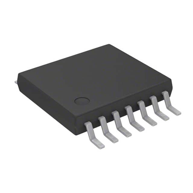
- Part No.:
- MTCH105-I/ST
- Manufacturer:
- Microchip Technology
- Category:
- Sensor, Capacitive Touch
- Package:
- 14-TSSOP (0.173", 4.40mm Width)
- Datasheet:
-
 MTCH105-I/ST.pdf
- Description:
- IC PROXIMITY DETECTOR 14TSSOP
- Quantity:
- Payment:

- Shipping:

Inventory:3,866
Please send an inquiry. Send us your inquiry, and we will respond immediately.
Product details
Overview
MTCH105-I/ST from Microchip Technology is a 5-channel capacitive proximity and touch controller with active guarding, operating from 2.05V to 3.6V over –40°C to +85°C, delivering five independent open-drain digital outputs (MTO0–MTO4) for reliable touch detection in space-constrained consumer and appliance interfaces.
For engineers reviewing the MTCH105-I/ST datasheet, MTCH105-I/ST pinout, MTCH105-I/ST application, or MTCH105-I/ST equivalent, this device offers configurable sensitivity via MTSA, selectable low-power mode via MTPM, active guard support on MTI2, and noise-suppressing smart scan scheduling-key selection criteria for robust human-interface designs.
Technical Context
The MTCH105-I/ST implements a dedicated capacitive sensing engine with multi-stage active noise suppression filters and automatic environmental compensation, enabling stable operation in electrically noisy environments without host MCU intervention. It supports up to five sensor inputs (MTI0–MTI4), one of which (MTI2) doubles as an active guard output when enabled via GC control.
Sensing is configured through analog voltage on MTSA (linear sensitivity scaling from GND = max to VDD = min) and digital logic level on MTPM (VDD = fast response/high power, GND = slow response/low power). All five MTOx outputs are open-drain, requiring external pull-ups and asserting low on detection.
Key Specifications
| Parameter | Value and Actual Design Meaning |
|---|---|
| Channels | 5 independent capacitive sensor inputs (MTI0–MTI4) |
| Active Guard Support | Yes - MTI2 can be configured as active guard output to shield adjacent sensors |
| Output Type | 5 open-drain digital outputs (MTO0–MTO4), active-low detection signals |
| Supply Voltage | 2.05V to 3.6V - compatible with single-cell Li-ion and 3.3V system rails |
| Operating Temp | –40°C to +85°C - qualified for industrial and white-goods ambient conditions |
| Sensitivity Control | Analog-adjustable via MTSA pin (0–VDD linear mapping) |
| Power Mode Select | Digital-selectable via MTPM pin (VDD = high-speed, GND = low-power) |
Pinout & Package
MTCH105-I/ST is packaged in a 14-lead SOIC (Small Outline Integrated Circuit) with 1.27 mm pitch, optimized for automated assembly and thermal performance in compact PCB layouts.
| Pin/Terminal | Circuit Role | Design Meaning |
|---|---|---|
| VDD | Power supply input | Primary 2.05–3.6V supply rail; decoupling capacitor required near pin |
| MTI0–MTI4 | Sensor input channels | Capacitive sense node inputs; each requires ≥4.7 kΩ series resistor for HF noise immunity |
| MTPM | Low-power mode select | Logic-level input: GND enables low-power/slower response; VDD enables full-speed operation |
| MTI2/Guard | Guard-capable sensor input | Configurable as sensor input or active guard output to reduce crosstalk and EMI coupling |
| MTO0–MTO4 | Digital detection outputs | Open-drain outputs; require external pull-up; drive low on proximity/touch event |
| MTSA | Sensitivity adjust input | Analog voltage input (0–VDD) setting linear sensitivity scale across all channels |
| VSS | Ground reference | System ground return; must be low-impedance connection to minimize noise |
Key Features
| Feature | Design Value |
|---|---|
| Multi-stage active noise suppression | Hardware-accelerated filtering eliminates line-frequency interference and RF noise without host CPU load |
| Adjustable sensitivity with sensor-size compensation | MTSA voltage scaling adapts detection threshold to varying electrode geometry and overlay thickness |
| Smart scan scheduling | Automatic interleaving of sensor scans minimizes mutual coupling and improves multi-touch stability |
| Threshold hysteresis | Prevents false toggling near detection threshold by maintaining distinct on/off voltage margins |
| Brown-out protection | Internal circuitry holds outputs inactive during supply ramp-up or dip below 1.8V, ensuring glitch-free startup |
Applications
| Light Switch Interface | Portable Device Enabler |
|---|---|
Use Scenario: Wall-mounted touch-sensitive light controls replacing mechanical switches in residential and commercial lighting. IC Role / Device Role / Timing Role: Standalone proximity/touch detector generating discrete ON/OFF signals for relay or TRIAC driver stages. Use Value: Eliminates moving parts and wear-out mechanisms while supporting glass or plastic overlays up to 8 mm thick. | Use Scenario: Wake-on-approach functionality in tablets, e-readers, and handheld medical devices. IC Role / Device Role / Timing Role: Ultra-low-power proximity monitor that asserts interrupt to host MCU only upon hand presence, extending battery life. Use Value: Enables <10 µA typical standby current via MTPM-controlled low-power mode, reducing system quiescent draw. |
| White Goods Control Panel | Office Equipment Activation |
Use Scenario: Touch-responsive control surfaces on refrigerators, dishwashers, and washing machines exposed to moisture and temperature variation. IC Role / Device Role / Timing Role: Environmental-compensating touch controller immune to condensation, humidity drift, and EMI from motors/compressors. Use Value: Automatic baseline recalibration maintains consistent sensitivity across –40°C to +85°C and >95% RH conditions. | Use Scenario: Backlight activation for copiers, printers, and multifunction peripherals when user approaches the control panel. IC Role / Device Role / Timing Role: Proximity-triggered signal generator interfacing directly with LED driver ICs or microcontroller GPIOs. Use Value: Five independent channels allow simultaneous monitoring of multiple zones (e.g., keypad, display edge, paper tray) with no software overhead. |
Equivalent & Alternatives
The following parts are listed as comparable options for similar capacitive proximity and touch controller applications.
| Alternative Part | Technical Difference | Application Difference | Selection Advice |
|---|---|---|---|
| MTCH102-I/SN | 2-channel version in 8-lead SOIC/DFN; lacks MTI3/MTI4 and MTO3/MTO4 pins | Suitable only for dual-sensor applications (e.g., simple on/off toggle); no guard capability on MTI1 | Select when board space and channel count are constrained and active guarding is not required. |
| CY8CMBR2016 | Cypress (Infineon) CapSense® device with 16-channel capacity, I²C interface, and firmware-configurable parameters | Requires host MCU for configuration and calibration; supports gesture recognition and slider implementation | Select when programmability, higher channel density, or advanced UI features outweigh need for autonomous operation. |
Compared with MTCH105-I/ST, MTCH102-I/SN reduces channel count and guard capability but lowers BOM cost and footprint; CY8CMBR2016 adds configurability and scalability at the expense of added firmware complexity and external component dependencies.
Availability
MTCH105-I/ST is available at Aetrix Electronics and suitable for light switch interfaces, portable device enablers, and white goods control panels requiring stable component supply, long-term industrial availability, and RoHS-compliant packaging.
Supply support for MTCH105-I/ST includes scheduled delivery planning, volume procurement assistance, BOM continuity management, traceable sourcing, and lifecycle availability coordination for OEM customers, industrial embedded developers, connected-device designers, and electronics production programs.
Manufacturer
Microchip Technology Inc. is a leading provider of microcontrollers, analog components, and interface ICs, headquartered in Chandler, Arizona, with global design and manufacturing operations certified to ISO/TS-16949.
The MTCH105-I/ST belongs to Microchip's mTouch® family of autonomous capacitive controllers, designed specifically for cost-sensitive, low-power human-interface applications where minimal host interaction and high noise immunity are critical.
FAQ
What is the function of the MTSA pin on the MTCH105-I/ST?
The MTSA pin on the MTCH105-I/ST is an analog input that sets global sensitivity across all five channels: applying GND yields maximum sensitivity, VDD yields minimum, and intermediate voltages provide linear scaling. This allows precise tuning for different overlay materials and electrode sizes without firmware changes, making MTCH105-I/ST ideal for production variants with diverse mechanical designs.
How does active guarding work on the MTCH105-I/ST?
Active guarding on the MTCH105-I/ST uses the MTI2 pin (configured as Guard via GC control) to drive a shielding waveform in-phase with the target sensor signal, minimizing voltage differential and capacitive coupling to noise sources. This significantly improves SNR in dense layouts or near noisy traces-confirmed in MTCH105-I/ST's noise suppression architecture and validated in Microchip's application notes for white goods and office equipment.
Can the MTCH105-I/ST operate from a 1.8V supply?
No, the MTCH105-I/ST has a specified minimum supply voltage of 2.05V and will not function reliably below that threshold. Operation outside the 2.05V–3.6V range may result in undefined behavior, failed detection, or brown-out lockup. For 1.8V systems, designers must use level-shifting or select alternative controllers such as Microchip's MTCH6301, not the MTCH105-I/ST.
What package type is used for the MTCH105-I/ST part number?
MTCH105-I/ST uses a 14-lead SOIC package with standard 1.27 mm lead pitch and JEDEC MS-012AC dimensions. The "ST" suffix explicitly denotes this SOIC variant, distinguishing it from the QFN-packaged MTCH105-I/QN (16-lead) and confirming compatibility with conventional reflow and wave-solder processes.
Does the MTCH105-I/ST require firmware or host processor configuration?
No, the MTCH105-I/ST operates autonomously with zero firmware dependency: all sensing, noise filtering, and output generation occur internally. Configuration is done solely via external pin states (MTPM, MTSA, GC) and passive components-no I²C, SPI, or programming interface exists. This makes MTCH105-I/ST uniquely suited for ultra-simple, cost-sensitive designs where host MCU resources are limited or unavailable.
MTCH105-I/ST Specifications
- Product attributes
- Attribute value
- Manufacturer:
- Microchip Technology
- Package/Case:
- 14-TSSOP (0.173", 4.40mm Width)
- Series:
- -
- Packaging:
- Tube
- Product Status:
- Active
- Programmable:
- Not Verified
- Type:
- Buttons
- Proximity Detection:
- Yes
- Number of Inputs:
- Up to 5
- LED Driver Channels:
- Up to 5
- Interface:
- Open Drain
- Resolution:
- -
- Voltage - Supply:
- 2.05V ~ 3.6V
- Current - Supply:
- 80mA
- Operating Temperature:
- -40°C ~ 85°C
- Grade:
- -
- Qualification:
- -
- Mounting Type:
- Surface Mount
- Supplier Device Package:
- 14-TSSOP
MTCH105-I/ST FAQ
1.How can I place an order for MTCH105-I/ST through Aetrix?
Please submit a Request for Quotation (RFQ) for MTCH105-I/ST on Aetrix. Our sales agent will provide a competitive quotation and guide you through the order confirmation once you accept the terms.
2.Are the price and stock information for MTCH105-I/ST reliable?
The price and inventory of MTCH105-I/ST are updated periodically and may fluctuate due to market conditions. Stock and pricing data are typically refreshed every 24 hours. Quotation validity for MTCH105-I/ST is usually 5 days.
3.What payment methods are accepted for MTCH105-I/ST?
We accept Wire Transfer, PayPal, Credit Card, Western Union, MoneyGram, and Escrow for MTCH105-I/ST transactions.
Note: Certain payment methods may incur a processing fee.
4.How is shipping managed for MTCH105-I/ST?
MTCH105-I/ST orders can be shipped via leading logistics carriers, including DHL, UPS, FedEx, TNT, or Registered Mail.
Once your MTCH105-I/ST order is processed, you will receive an email with the shipment details and tracking number.
Note: Tracking information may take up to 24 hours to appear. Express delivery typically takes 3–5 business days.
5.How can I obtain technical support or documentation for MTCH105-I/ST?
For technical support, including MTCH105-I/ST datasheets, pinout diagrams, or application guidance, please contact our engineering support team. They can provide detailed documentation and assistance for your MTCH105-I/ST requirements.
6.How does Aetrix verify that MTCH105-I/ST is sourced from the original manufacturer or authorized distributors?
All MTCH105-I/ST products on Aetrix are procured from qualified distributors and authorized channels. Our dedicated quality assurance team conducts strict verification, including traceability checks and, if necessary, third-party testing. This ensures that MTCH105-I/ST meets industry standards.
7.What is the process for return or replacement of MTCH105-I/ST?
All MTCH105-I/ST units undergo pre-shipment inspection (PSI). If there is an issue with MTCH105-I/ST, returns or replacements are accepted under the following conditions:
1.Quantity discrepancies, incorrect items, or visible external defects (such as breakage or corrosion), acknowledged by Aetrix.
2.The issue is reported within 90 days of delivery.
3.The MTCH105-I/ST part is unused and in its original packaging.
Return procedure for MTCH105-I/ST:
1.Submit a request within 90 days.
2.Obtain a Return Material Authorization (RMA) from Aetrix.
MTCH105-I/ST Tags

-
IQS228B00000000TSR
Azoteq (Pty) Ltd

-
MTCH101T-I/OT
Microchip Technology
-
IQS323001CSR
Azoteq (Pty) Ltd

-
AT42QT1010-TSHR
Microchip Technology
-
AT42QT1012-TSHR
Microchip Technology
-
AT42QT1011-TSHR
Microchip Technology

-
CAP1206-1-SL-TR
Microchip Technology

-
MTCH102T-I/MS
Microchip Technology
-
IQS323001DNR
Azoteq (Pty) Ltd
-
AT42QT1070-SSUR
Microchip Technology
-
CAP1188-1-CP-TR
Microchip Technology
-
AT42QT1110-AUR
Microchip Technology
Tech Hub

TTL and CMOS logic families differ in thresholds, loading, output drive, power and timing. This engineering guide compares 74HC and 74HCT, calculates noise margins and checks 3.3 V/5 V compatibility.

A practical engineering guide to 3.3V and 5V logic compatibility, input thresholds, resistor dividers, translator ICs, MOSFET level shifting, I2C pull-ups, timing limits and power-sequencing risks.

The 74HC595 uses push-pull logic outputs, while the TPIC6B595 uses 50 V open-drain DMOS sinks for higher-power loads. This guide compares timing, current limits, 3.3 V interfacing, load wiring, thermal…

The 74HC595 converts serial data into eight stable parallel outputs. This guide covers pin functions, shift and storage timing, OE and MR behavior, drive-current limits, cascading, voltage compatibilit…

A technical comparison of level-sensitive latches and edge-triggered flip-flops, covering timing windows, setup and hold limits, master–slave operation, time borrowing, race-through, HDL inference and…

A D latch stores one bit while Enable controls when data can pass. This reference covers gate-level operation, truth tables, transparency, setup and hold timing, LE versus OE, common ICs and practical …

An SR latch stores one bit through cross-coupled feedback. This engineering reference covers NOR and NAND implementations, truth tables, forbidden-state recovery, gated operation, switch debouncing, fa…

Latch circuits retain one bit through feedback. This technical reference covers SR and D latches, truth tables, transparency, timing limits, latch-versus-flip-flop behavior, applications and common log…

An engineering guide to LED driver operation, constant-current and constant-voltage outputs, linear and switching topologies, dimming, IC selection, calculations, replacement compatibility, and fault c…

Operational amplifier guide covering op amp basics, feedback, ideal vs real op amps, common configurations, buffer circuits, offset, bias current, gain-bandwidth, slew rate, rail-to-rail limits and sel…


