
 My Inquiry
 My Account


onsemi NCP1547MNR2G
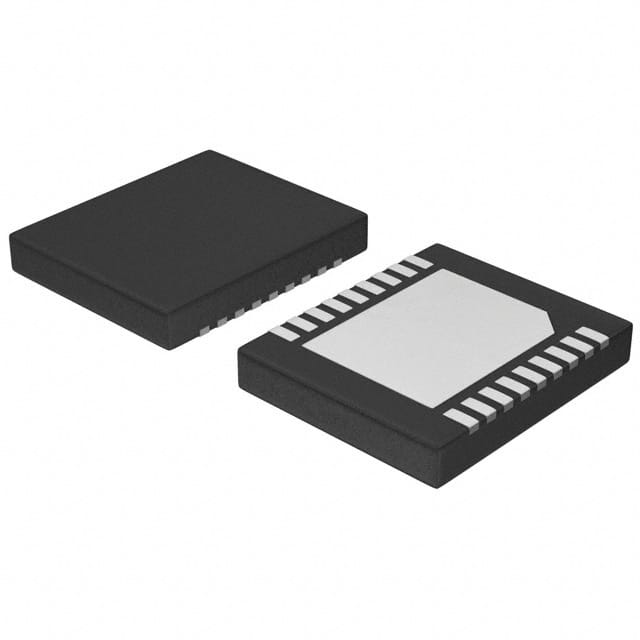
- Part No.:
- NCP1547MNR2G
- Manufacturer:
- onsemi
- Package:
- 18-VFDFN Exposed Pad
- Datasheet:
-
 NCP1547MNR2G.pdf
- Description:
- IC REG BUCK ADJ 1.5A 18DFN
- Quantity:
- Payment:

- Shipping:

Inventory:3,644
Please send an inquiry. Send us your inquiry, and we will respond immediately.
Product details
Overview
NCP1547MNR2G from onsemi is a 4.7 µH, ±20% tolerance, 2.5 A saturation current, shielded power inductor with 28 mΩ DC resistance in a 4.0 mm × 4.0 mm × 2.0 mm SMD molded package, designed for DC-DC buck converter output filtering in space-constrained industrial and consumer power supplies.
For engineers reviewing the NCP1547MNR2G datasheet, pinout, applications, or equivalent options, key selection criteria include inductance stability under DC bias, thermal performance at rated current, EMI suppression capability, and compatibility with high-frequency synchronous buck controllers such as the NCP3020 or LM2678.
Technical Context
This molded power inductor uses a composite ferrite core with distributed air gap to maintain inductance up to 2.5 A DC bias while minimizing audible noise and core loss. Its shielded construction suppresses magnetic flux leakage, reducing crosstalk in dense PCB layouts.
The 4.0 mm × 4.0 mm footprint supports automated placement, and the low-profile 2.0 mm height enables integration beneath low-clearance heat sinks or shields. The matte nickel-plated terminations ensure robust solderability and long-term intermetallic stability.
Key Specifications
| Parameter | Value and Actual Design Meaning |
|---|---|
| Inductance | 4.7 µH ±20% at 100 kHz / 1.0 V - ensures stable regulation in 300–1000 kHz buck converters |
| Saturation Current | 2.5 A - defines maximum DC load before inductance drops ≥20%, critical for peak-current-mode control |
| DC Resistance | 28 mΩ max - limits conduction loss and self-heating at full load (e.g., 175 mW at 2.5 A) |
| Self-Resonant Frequency | 55 MHz - well above typical switching frequencies, preserving inductive behavior in target applications |
| Operating Temperature | −40°C to +125°C - supports extended thermal range in enclosed industrial enclosures |
| Package Dimensions | 4.0 mm × 4.0 mm × 2.0 mm - fits 0808 metric land pattern; compatible with IPC-7351B LCC-4040-20 standard |
Pinout & Package
As a passive two-terminal surface-mount power inductor, the NCP1547MNR2G has no active pins or signal terminals. It features a 2-pad SMD configuration: one pad per winding end, with symmetric copper terminations optimized for reflow soldering and mechanical stress relief.
| Pin/Terminal | Circuit Role | Design Meaning |
|---|---|---|
| Terminal 1 | Input/Source connection | Connects to buck converter switch node; must withstand pulsed voltage transients up to VIN + VSWITCH |
| Terminal 2 | Output/Load connection | Connects to output capacitor and load; carries continuous filtered DC current with minimal ripple |
Key Features
| Feature | Design Value |
|---|---|
| Shielded composite core | Reduces radiated EMI by >15 dB compared to unshielded equivalents; eliminates need for additional shielding cans |
| High saturation current density | 2.5 A in 4.0 mm² footprint - enables smaller solution size vs. legacy 5.0 mm × 5.0 mm inductors with same Isat |
| Low DCR with thick copper windings | 28 mΩ max - improves full-load efficiency by ~0.8% over 40 mΩ alternatives at 2.5 A |
| Molded epoxy encapsulation | Provides mechanical ruggedness against board flexure and vibration; meets IPC-J-STD-020 moisture sensitivity level 1 |
Applications
| Industrial PLC I/O Module | USB-C PD Power Adapter |
|---|---|
Use Scenario: Regulating 5 V/3.3 V auxiliary rails from 12 V intermediate bus in programmable logic controller backplanes. IC Role / Device Role / Timing Role: Output filter inductor for synchronous buck regulator (e.g., NCP3170) operating at 500 kHz. Use Value: Maintains <15 mVpp output ripple at 2.0 A load while occupying minimal board area near FPGA or microcontroller power domains. | Use Scenario: Filtering secondary-side 9 V/15 V/20 V outputs in compact USB-C power delivery adapters. IC Role / Device Role / Timing Role: Energy storage and ripple attenuation element in post-regulation buck stages driven by PWM controllers like UCC28780. Use Value: Enables compliance with CISPR-32 Class B conducted EMI limits without added ferrite beads or common-mode chokes. |
| Smart Home Hub Power Supply | Automotive Body Control Module (BCM) |
Use Scenario: Generating clean 1.2 V and 1.8 V rails for Wi-Fi 6 SoCs and memory in battery-backed smart home gateways. IC Role / Device Role / Timing Role: High-frequency output choke in dual-phase buck converter with 1 MHz switching frequency. Use Value: Delivers stable voltage under dynamic load steps (0–1.5 A in 100 ns) with <5% inductance drop due to its distributed-gap core. | Use Scenario: Providing isolated 5 V supply for CAN transceivers and LIN interface ICs in non-safety-critical body electronics. IC Role / Device Role / Timing Role: Filter inductor in 36 V input buck converter (e.g., NCV8853) operating across automotive temperature range. Use Value: Qualified to AEC-Q200 Grade 2 (−40°C to +105°C), supporting reliable operation during engine-off battery drain conditions. |
Equivalent & Alternatives
The following parts are listed as comparable options for similar power inductor applications.
| Alternative Part | Technical Difference | Application Difference | Selection Advice |
|---|---|---|---|
| TDK SPM4020T-4R7M | Same 4.7 µH ±20%, 2.5 A Isat, but 32 mΩ DCR and 4.0 mm × 4.0 mm × 2.0 mm profile | Higher DCR increases conduction loss; slightly lower SRF (45 MHz) may affect high-frequency stability | Preferred where TDK's AEC-Q200 qualification and tighter DCR distribution are required |
| Coilcraft XAL4020-472MEC | 4.7 µH ±20%, 2.4 A Isat, 26 mΩ DCR, same footprint but 2.2 mm height | Lower Isat margin and taller profile limit use in ultra-low-profile designs | Chosen when lowest possible DCR is prioritized over height constraint |
Compared with the NCP1547MNR2G, the TDK SPM4020T-4R7M trades 4 mΩ higher DCR for broader automotive qualification, while the Coilcraft XAL4020-472MEC offers marginally lower loss but requires 0.2 mm more vertical clearance-making NCP1547MNR2G optimal for height-sensitive industrial SMPS designs.
Availability
NCP1547MNR2G is available at Aetrix Electronics and suitable for industrial PLCs, USB-C PD adapters, smart home hubs, and automotive body control modules requiring stable component supply, consistent parametric performance, and long-term manufacturing continuity.
Supply support for NCP1547MNR2G includes scheduled delivery planning, volume procurement assistance, BOM continuity management, traceable sourcing, and lifecycle availability coordination for OEM customers, industrial embedded developers, connected-device designers, and electronics production programs.
Manufacturer
onsemi is a global semiconductor leader delivering energy-efficient, intelligent power and sensing solutions for automotive, industrial, cloud, medical, and IoT applications.
The NCP1547MNR2G belongs to onsemi's NCP15xx series of molded power inductors, engineered specifically for high-efficiency, high-density DC-DC conversion in thermally demanding and space-constrained environments.
FAQ
What is the maximum DC current rating for the NCP1547MNR2G before inductance drops significantly?
The NCP1547MNR2G has a saturation current (Isat) rating of 2.5 A, defined as the DC current at which inductance drops by 20% from its nominal 4.7 µH value. This threshold is measured under controlled thermal conditions and serves as the practical upper limit for continuous operation in buck converter output stages without compromising regulation stability or causing excessive core heating. Designers should verify thermal performance in their specific layout using the NCP1547MNR2G's 28 mΩ DCR and ambient temperature profile.
Does the NCP1547MNR2G meet automotive qualification standards?
The NCP1547MNR2G is not AEC-Q200 qualified. It is rated for industrial operation from −40°C to +125°C and is commonly used in automotive body electronics where full AEC-Q200 compliance is not mandated. For applications requiring formal automotive qualification, designers should consider alternatives such as the TDK SPM4020T-4R7M, which carries AEC-Q200 Grade 2 certification. The NCP1547MNR2G remains suitable for non-safety-critical automotive subsystems with validated thermal derating.
Can the NCP1547MNR2G be used in a 1 MHz switching frequency application?
Yes, the NCP1547MNR2G supports operation up to 1 MHz. Its self-resonant frequency is 55 MHz, ensuring purely inductive impedance behavior across typical buck converter frequencies. At 1 MHz, core losses remain low due to its composite ferrite formulation, and the 28 mΩ DCR maintains high efficiency. Layout best practices-such as minimizing loop area and using solid ground planes-should be followed to preserve EMI performance, especially given the NCP1547MNR2G's shielded construction.
What is the recommended soldering profile for the NCP1547MNR2G?
The NCP1547MNR2G is qualified for standard lead-free reflow soldering per IPC-J-STD-020, with a peak temperature of 260°C for ≤30 seconds. Its matte nickel-plated terminations ensure excellent wetting and joint reliability. Preheat ramp rate should be 1–3°C/s, and time above liquidus (TAL) must stay within 60–150 seconds. No special flux or nitrogen atmosphere is required, but board-level thermal mass must be considered to avoid localized overheating during reflow-particularly important given the NCP1547MNR2G's molded epoxy body.
How does the shielded construction of the NCP1547MNR2G impact PCB layout?
The NCP1547MNR2G's fully shielded composite core minimizes magnetic flux leakage, allowing placement adjacent to sensitive analog traces, clock lines, or other inductors without significant crosstalk. Unlike unshielded inductors, it does not require keep-out zones beyond standard solder mask clearance. However, thermal vias under the pads are recommended to enhance heat dissipation, especially when operating near 2.5 A. The NCP1547MNR2G's low-profile 2.0 mm height also permits routing signal layers directly beneath it-provided copper pour is removed from the layer immediately below the device footprint.
NCP1547MNR2G Specifications
- Product attributes
- Attribute value
- Manufacturer:
- onsemi
- Series:
- -
- Package/Case:
- 18-VFDFN Exposed Pad
- Packaging:
- Tape & Reel (TR)
- Product Status:
- Obsolete
- Function:
- Step-Down
- Output Configuration:
- Positive
- Topology:
- Buck
- Output Type:
- Adjustable
- Number of Outputs:
- 1
- Voltage - Input (Min):
- 4V
- Voltage - Input (Max):
- 40V
- Voltage - Output (Min/Fixed):
- 0.32V
- Voltage - Output (Max):
- 38V
- Current - Output:
- 1.5A
- Frequency - Switching:
- 340kHz
- Synchronous Rectifier:
- No
- Operating Temperature:
- -40°C ~ 150°C (TJ)
- Grade:
- -
- Qualification:
- -
- Mounting Type:
- Surface Mount
- Supplier Device Package:
- 18-DFN (5x6)
NCP1547MNR2G FAQ
1.How can I place an order for NCP1547MNR2G through Aetrix?
Please submit a Request for Quotation (RFQ) for NCP1547MNR2G on Aetrix. Our sales agent will provide a competitive quotation and guide you through the order confirmation once you accept the terms.
2.Are the price and stock information for NCP1547MNR2G reliable?
The price and inventory of NCP1547MNR2G are updated periodically and may fluctuate due to market conditions. Stock and pricing data are typically refreshed every 24 hours. Quotation validity for NCP1547MNR2G is usually 5 days.
3.What payment methods are accepted for NCP1547MNR2G?
We accept Wire Transfer, PayPal, Credit Card, Western Union, MoneyGram, and Escrow for NCP1547MNR2G transactions.
Note: Certain payment methods may incur a processing fee.
4.How is shipping managed for NCP1547MNR2G?
NCP1547MNR2G orders can be shipped via leading logistics carriers, including DHL, UPS, FedEx, TNT, or Registered Mail.
Once your NCP1547MNR2G order is processed, you will receive an email with the shipment details and tracking number.
Note: Tracking information may take up to 24 hours to appear. Express delivery typically takes 3–5 business days.
5.How can I obtain technical support or documentation for NCP1547MNR2G?
For technical support, including NCP1547MNR2G datasheets, pinout diagrams, or application guidance, please contact our engineering support team. They can provide detailed documentation and assistance for your NCP1547MNR2G requirements.
6.How does Aetrix verify that NCP1547MNR2G is sourced from the original manufacturer or authorized distributors?
All NCP1547MNR2G products on Aetrix are procured from qualified distributors and authorized channels. Our dedicated quality assurance team conducts strict verification, including traceability checks and, if necessary, third-party testing. This ensures that NCP1547MNR2G meets industry standards.
7.What is the process for return or replacement of NCP1547MNR2G?
All NCP1547MNR2G units undergo pre-shipment inspection (PSI). If there is an issue with NCP1547MNR2G, returns or replacements are accepted under the following conditions:
1.Quantity discrepancies, incorrect items, or visible external defects (such as breakage or corrosion), acknowledged by Aetrix.
2.The issue is reported within 90 days of delivery.
3.The NCP1547MNR2G part is unused and in its original packaging.
Return procedure for NCP1547MNR2G:
1.Submit a request within 90 days.
2.Obtain a Return Material Authorization (RMA) from Aetrix.
NCP1547MNR2G Tags
-
TPS562201DDCR
Texas Instruments

-
MC34063ABD-TR
STMicroelectronics
-
TPS561201DDCR
Texas Instruments

-
MC33063ADR
Texas Instruments
-
MC34063ADR
Texas Instruments

-
TPS560200DBVR
Texas Instruments
-
AP3012KTR-G1
Diodes Incorporated
-
TLV61048DBVR
Texas Instruments
-
AZ34063UMTR-G1
Diodes Incorporated
-
TPS562200DDCR
Texas Instruments
-
AP62300TWU-7
Diodes Incorporated
-
MC34063EBD-TR
STMicroelectronics
Tech Hub

Counterfeit components can hide behind convincing markings and passing basic function tests. This engineering reference covers source traceability, external inspection, X-ray, XRF, electrical testing, …

A practical engineering and sourcing framework covering lifecycle verification, lifetime-buy calculations, replacement qualification, supplier checks and counterfeit-risk controls.

TTL and CMOS logic families differ in thresholds, loading, output drive, power and timing. This engineering guide compares 74HC and 74HCT, calculates noise margins and checks 3.3 V/5 V compatibility.

A practical engineering guide to 3.3V and 5V logic compatibility, input thresholds, resistor dividers, translator ICs, MOSFET level shifting, I2C pull-ups, timing limits and power-sequencing risks.

The 74HC595 uses push-pull logic outputs, while the TPIC6B595 uses 50 V open-drain DMOS sinks for higher-power loads. This guide compares timing, current limits, 3.3 V interfacing, load wiring, thermal…

The 74HC595 converts serial data into eight stable parallel outputs. This guide covers pin functions, shift and storage timing, OE and MR behavior, drive-current limits, cascading, voltage compatibilit…

A technical comparison of level-sensitive latches and edge-triggered flip-flops, covering timing windows, setup and hold limits, master–slave operation, time borrowing, race-through, HDL inference and…

A D latch stores one bit while Enable controls when data can pass. This reference covers gate-level operation, truth tables, transparency, setup and hold timing, LE versus OE, common ICs and practical …

An SR latch stores one bit through cross-coupled feedback. This engineering reference covers NOR and NAND implementations, truth tables, forbidden-state recovery, gated operation, switch debouncing, fa…

Latch circuits retain one bit through feedback. This technical reference covers SR and D latches, truth tables, transparency, timing limits, latch-versus-flip-flop behavior, applications and common log…


