
 My Inquiry
 My Account


onsemi NCP3521DMR2G
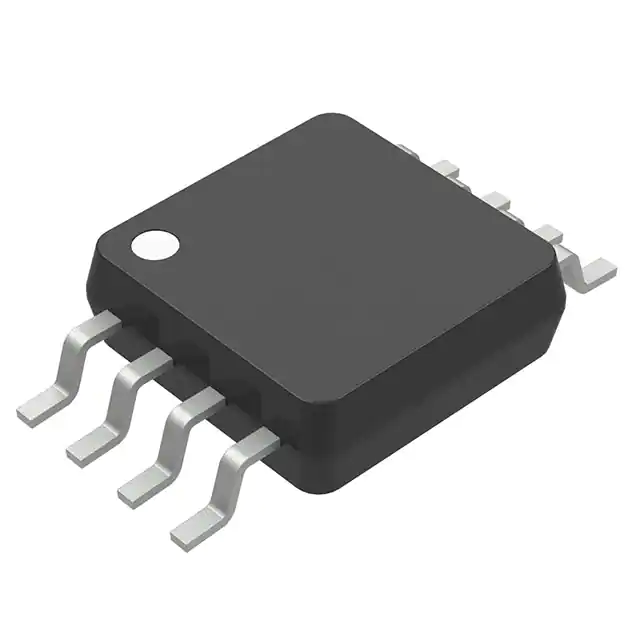
- Part No.:
- NCP3521DMR2G
- Manufacturer:
- onsemi
- Package:
- 8-TSSOP, 8-MSOP (0.118", 3.00mm Width)
- Datasheet:
-
 NCP3521DMR2G.pdf
- Description:
- IC LNR REG CTRLR 1OUT MICRO8
- Quantity:
- Payment:

- Shipping:

Inventory:2,050
Please send an inquiry. Send us your inquiry, and we will respond immediately.
Product details
Overview
NCP3521DMR2G from onsemi is a fixed 1.5 V low-dropout (LDO) regulator controller designed to drive an external NMOS FET for high-current, ultra-low-dropout power regulation. It delivers ±1% output voltage tolerance, supports up to 3 A load current with NTMS4107N, features non-rush startup (NRCS), short-circuit protection, and thermal shutdown-targeting FPGA core supply and LCD TV main rail applications.
For engineers reviewing the NCP3521DMR2G datasheet, pinout, applications, or equivalent options, key selection criteria include its 1.5 V fixed output, Micro8 package with gate/source/drain sensing pins, NRCS-controlled slew rate, VD undervoltage lockout at 0.90–1.20 V, and compatibility with industry-standard NFETs like Si4866DY.
Technical Context
The NCP3521DMR2G implements a precision error amplifier with Kelvin-sense-capable VFB input, enabling tight regulation under dynamic loads. Its VS pin provides programmable pulldown current (1.2 mA active / 220 mA shutdown) for fast transient response and controlled turn-off.
Startup and fault management are handled by integrated timers: a 50 µs power-on reset circuit governs EN-to-G delay and VCC recovery timing, while the NRCS capacitor simultaneously sets soft-start slew rate and short-circuit detection timeout-triggering latch-off when VFB drops below 35% of nominal output.
Key Specifications
| Parameter | Value and Actual Design Meaning |
|---|---|
| Output Voltage | Fixed 1.5 V ±1% - ensures stable core bias for FPGA I/O banks and LCD panel logic without external resistor divider. |
| Feedback Reference | 1.500 V typical at VFB - enables accurate closed-loop regulation independent of external FET RDS(on) variation. |
| Dropout Support | Ultra-low dropout enabled via external NFET - allows operation with VIN as low as VOUT + VGS(th) + ILOAD × RDS(on), not fixed IC dropout. |
| NRCS Function | Linear 20 µA charge current - programs predictable output voltage ramp time (e.g., 325 µs with 0.01 µF) to limit inrush stress on downstream capacitors. |
| Short-Circuit Threshold | VFB < 35% of VOUT - detects hard shorts before output collapse, initiating 1.3 V NRCS-triggered latch-off within defined timing window. |
| VCC UVLO | 4.35 V rising threshold with 160 mV hysteresis - prevents erratic operation during brown-out conditions in 5 V supply rails. |
| Thermal Shutdown | 180 °C typical trip with 15 °C hysteresis - protects die during sustained overload or poor heatsinking; restarts via NRCS soft-start after cooldown. |
Pinout & Package
Package: Micro8 (Case 846A-02), Pb-free, 3.00 mm × 3.00 mm body, 0.65 mm pitch, 1.10 mm max height.
| Pin/Terminal | Circuit Role | Design Meaning |
|---|---|---|
| 1 - NRCS | Non-Rush Current Startup control | Capacitor-connected node that linearly charges to program output slew rate and serves as short-circuit detection integrator. |
| 2 - GND | Power ground reference | Common return for internal bias, error amplifier, and VS pulldown; requires low-impedance PCB connection to minimize noise coupling. |
| 3 - EN | Enable input | TTL-compatible logic input (0.8 V low / 2.0 V high); asserts sleep mode (<10 µA ICC) when low, with 60 mV hysteresis for noise immunity. |
| 4 - VCC | IC supply input | Accepts 4.5–5.5 V; includes 4.35 V UVLO with hysteresis to prevent oscillation during marginal 5 V rail conditions. |
| 5 - VFB | Feedback input | Kelvin-sense point for error amplifier; connects to regulated output via dedicated trace to reject PCB IR drop errors. |
| 6 - VS | Source sense & pulldown driver | Provides 1.2 mA active pulldown (220 mA during shutdown) to suppress overshoot and accelerate turn-off of external FET. |
| 7 - G | Gate drive output | High-current NMOS gate driver (±4 mA) optimized for fast switching of logic-level NFETs like NTMS4107N or Si4866DY. |
| 8 - VD | Drain voltage sense | Monitors external FET drain for UVLO (0.90–1.20 V threshold); ensures regulation only when sufficient headroom exists across FET. |
Key Features
| Feature | Design Value |
|---|---|
| Fixed 1.5 V output | Eliminates external resistor network, reducing BOM count and layout sensitivity while maintaining ±1% accuracy over temperature and load. |
| NRCS + SCP dual-function pin | Single capacitor configures both soft-start ramp time and short-circuit detection timeout-reducing component count and PCB area. |
| VCC and VD undervoltage lockout | Independent monitoring of IC supply and FET drain ensures safe startup only when both rails meet minimum headroom requirements. |
| VS pulldown current control | Configurable 1.2 mA / 220 mA sink capability minimizes output overshoot at power-up and accelerates shutdown during fault events. |
| Thermal shutdown with hysteresis | 180 °C trip with 15 °C hysteresis prevents thermal cycling; automatic recovery via NRCS soft-start avoids repeated latching under marginal cooling. |
Applications
| FPGA Core Supply | LCD TV Main Rail |
|---|---|
|
Use Scenario: Powering 1.5 V I/O banks of Xilinx Artix-7 or Intel Cyclone V FPGAs during configuration and high-speed data transfer. IC Role / Device Role / Timing Role: LDO controller regulating output via external NFET to maintain tight voltage tolerance under 0–3 A dynamic load steps. Use Value: NRCS prevents inrush into large FPGA decoupling banks; VS pulldown limits overshoot during hot-plug events, protecting I/O structures. |
Use Scenario: Delivering stable 1.5 V to LCD panel timing controllers and interface logic in 4K UHD televisions. IC Role / Device Role / Timing Role: High-current LDO controller driving low-RDS(on) NFET to sustain 3 A peak loads with minimal dropout under varying backlight dimming conditions. Use Value: VD UVLO blocks regulation if input rail sags below safe FET operating margin; thermal shutdown prevents damage during extended ambient heat exposure. |
| Gaming Console SoC I/O | Networking ASIC Bias |
|
Use Scenario: Supplying 1.5 V to GPU memory interfaces and PCIe SerDes buffers in next-gen gaming consoles. IC Role / Device Role / Timing Role: Fast-transient LDO controller using VS pulldown and Kelvin VFB sensing to suppress load-induced droop during burst-mode graphics rendering. Use Value: 50 µs EN-to-G delay synchronizes power enable with system reset sequencing; short-circuit latch prevents bus faults from propagating to adjacent rails. |
Use Scenario: Biasing 1.5 V auxiliary domains of multi-core networking ASICs in enterprise switches and routers. IC Role / Device Role / Timing Role: Enable-controlled LDO controller supporting deep-sleep modes (<10 µA ICC) during packet-idle periods while retaining fast wake-up capability. Use Value: EN hysteresis rejects noise on shared control buses; microsecond-scale NRCS discharge enables rapid re-enable after brief power interruptions. |
Equivalent & Alternatives
The following parts are listed as comparable options for similar LDO controller applications.
| Alternative Part | Technical Difference | Application Difference | Selection Advice |
|---|---|---|---|
| Rohm BD3521FVM | P2P pin-compatible with identical Micro8 footprint, same 1.5 V output and NRCS function; differs in VCC UVLO (4.25 V vs. 4.35 V) and thermal trip (165 °C vs. 180 °C). | Valid for drop-in replacement where board layout and thermal margin match original BD3521FVM design constraints. | Select when legacy BD3521FVM qualification data applies and no revision to thermal derating is required. |
| onsemi NCP3520DMR2G | Same Micro8 package and architecture, but fixed 1.2 V output; shares identical NRCS, SCP, EN, and VS functionality-only VFB reference differs. | Used where 1.2 V core rail is needed instead of 1.5 V; not interchangeable without schematic and layout modification. | Choose for 1.2 V systems requiring identical control features and timing behavior-enables common firmware and layout reuse. |
Compared with Rohm BD3521FVM, NCP3521DMR2G offers higher thermal shutdown threshold and tighter VCC UVLO hysteresis, improving robustness in noisy 5 V environments; versus NCP3520DMR2G, it provides identical control logic scaled to 1.5 V output, enabling platform-level voltage variant flexibility without architectural change.
Availability
NCP3521DMR2G is available at Aetrix Electronics and suitable for FPGA power delivery, LCD TV main rail regulation, and networking ASIC biasing requiring stable component supply, long-term lifecycle support, and Pb-free compliance.
Supply support for NCP3521DMR2G includes scheduled delivery planning, volume procurement assistance, BOM continuity management, traceable sourcing, and lifecycle availability coordination for OEM customers, industrial embedded developers, connected-device designers, and electronics production programs.
Manufacturer
onsemi (formerly ON Semiconductor) is a global semiconductor supplier focused on energy-efficient electronics, delivering silicon solutions for automotive, industrial, cloud, and intelligent edge applications.
The NCP3521DMR2G belongs to onsemi's NCP352X family of external-FET LDO controllers, engineered specifically for high-current, low-dropout DC-DC regulation in space-constrained consumer and computing platforms where thermal performance and transient response are critical.
FAQ
What is the primary function of the NRCS pin on the NCP3521DMR2G?
The NRCS pin on the NCP3521DMR2G controls non-rush current during startup by linearly charging an external capacitor to program output voltage slew rate. It also serves as the integrator for short-circuit detection-charging to 1.3 V triggers latch-off when VFB falls below 35% of 1.5 V. This dual use reduces component count while ensuring controlled power-up and reliable fault response in the NCP3521DMR2G.
Can the NCP3521DMR2G operate without an external MOSFET?
No, the NCP3521DMR2G cannot regulate voltage without an external NMOS FET. It is a controller-not a complete LDO-and relies on the external FET (e.g., NTMS4107N or Si4866DY) to source load current. The NCP3521DMR2G drives the gate (G pin), senses drain (VD), source (VS), and feedback (VFB) to close the regulation loop. Omitting the FET leaves no power path, rendering the NCP3521DMR2G nonfunctional as a regulator.
What is the minimum input voltage required for the NCP3521DMR2G to regulate 1.5 V output?
The NCP3521DMR2G itself has no fixed dropout voltage-it depends entirely on the selected external NMOS FET. Minimum input is determined by VOUT + VGS(th) + ILOAD × RDS(on). For example, with NTMS4107N (VGS(th) = 1.0 V, RDS(on) = 12 mΩ @ VGS = 4.5 V), at 3 A load, minimum VIN ≈ 1.5 V + 1.0 V + 0.036 V = 2.54 V. However, VD UVLO (0.90–1.20 V) must also be satisfied, requiring VIN > VOUT + VD_UVLO.
How does the VS pin improve transient response in the NCP3521DMR2G?
The VS pin on the NCP3521DMR2G provides active pulldown current (1.2 mA in run mode, 220 mA in shutdown) directly to the external FET's source node. During load transients, this sinks excess charge to suppress output overshoot at power-up and accelerates voltage collapse during turn-off or thermal fault. Unlike passive RC networks, VS delivers deterministic, current-limited response-critical for protecting sensitive 1.5 V logic in FPGA and ASIC applications using the NCP3521DMR2G.
Is the NCP3521DMR2G RoHS-compliant and halogen-free?
Yes, the NCP3521DMR2G is RoHS-compliant and halogen-free. The "G" suffix in the part number explicitly denotes Pb-free (lead-free) packaging per JEDEC J-STD-609, and onsemi confirms full compliance with EU RoHS Directive 2011/65/EU and JEDEC JS709B halogen-free requirements. The Micro8 package uses matte tin lead finish and green molding compound, verified in onsemi's material declarations for NCP3521DMR2G.
NCP3521DMR2G Specifications
- Product attributes
- Attribute value
- Manufacturer:
- onsemi
- Series:
- -
- Package/Case:
- 8-TSSOP, 8-MSOP (0.118", 3.00mm Width)
- Packaging:
- Tape & Reel (TR)
- Product Status:
- Obsolete
- Type:
- Positive Fixed
- Number of Outputs:
- 1
- Current - Supply:
- 1.7mA
- Voltage - Input:
- 4.35V ~ 7V
- Operating Temperature:
- -10°C ~ 150°C
- Mounting Type:
- Surface Mount
- Supplier Device Package:
- 8-MSOP
NCP3521DMR2G FAQ
1.How can I place an order for NCP3521DMR2G through Aetrix?
Please submit a Request for Quotation (RFQ) for NCP3521DMR2G on Aetrix. Our sales agent will provide a competitive quotation and guide you through the order confirmation once you accept the terms.
2.Are the price and stock information for NCP3521DMR2G reliable?
The price and inventory of NCP3521DMR2G are updated periodically and may fluctuate due to market conditions. Stock and pricing data are typically refreshed every 24 hours. Quotation validity for NCP3521DMR2G is usually 5 days.
3.What payment methods are accepted for NCP3521DMR2G?
We accept Wire Transfer, PayPal, Credit Card, Western Union, MoneyGram, and Escrow for NCP3521DMR2G transactions.
Note: Certain payment methods may incur a processing fee.
4.How is shipping managed for NCP3521DMR2G?
NCP3521DMR2G orders can be shipped via leading logistics carriers, including DHL, UPS, FedEx, TNT, or Registered Mail.
Once your NCP3521DMR2G order is processed, you will receive an email with the shipment details and tracking number.
Note: Tracking information may take up to 24 hours to appear. Express delivery typically takes 3–5 business days.
5.How can I obtain technical support or documentation for NCP3521DMR2G?
For technical support, including NCP3521DMR2G datasheets, pinout diagrams, or application guidance, please contact our engineering support team. They can provide detailed documentation and assistance for your NCP3521DMR2G requirements.
6.How does Aetrix verify that NCP3521DMR2G is sourced from the original manufacturer or authorized distributors?
All NCP3521DMR2G products on Aetrix are procured from qualified distributors and authorized channels. Our dedicated quality assurance team conducts strict verification, including traceability checks and, if necessary, third-party testing. This ensures that NCP3521DMR2G meets industry standards.
7.What is the process for return or replacement of NCP3521DMR2G?
All NCP3521DMR2G units undergo pre-shipment inspection (PSI). If there is an issue with NCP3521DMR2G, returns or replacements are accepted under the following conditions:
1.Quantity discrepancies, incorrect items, or visible external defects (such as breakage or corrosion), acknowledged by Aetrix.
2.The issue is reported within 90 days of delivery.
3.The NCP3521DMR2G part is unused and in its original packaging.
Return procedure for NCP3521DMR2G:
1.Submit a request within 90 days.
2.Obtain a Return Material Authorization (RMA) from Aetrix.
NCP3521DMR2G Tags

-
LT1575CS8#PBF
Analog Devices Inc.

-
RT9008GE
Richtek USA Inc.

-
S-816A40AMC-BAPT2U
ABLIC Inc.

-
MIC5159YM6-TR
Microchip Technology

-
MIC5156YM
Microchip Technology
-
MIC5156-3.3YM
Microchip Technology

-
MIC5158YM-TR
Microchip Technology
-
MAX8564AEUB+
Analog Devices Inc./Maxim Integrated
-
LT1573CS8#PBF
Analog Devices Inc.

-
UC2834DW
Texas Instruments
-
RT9194GE
Richtek USA Inc.
-
S-816A33AMC-BAIT2U
ABLIC Inc.
Tech Hub

Counterfeit components can hide behind convincing markings and passing basic function tests. This engineering reference covers source traceability, external inspection, X-ray, XRF, electrical testing, …

A practical engineering and sourcing framework covering lifecycle verification, lifetime-buy calculations, replacement qualification, supplier checks and counterfeit-risk controls.

TTL and CMOS logic families differ in thresholds, loading, output drive, power and timing. This engineering guide compares 74HC and 74HCT, calculates noise margins and checks 3.3 V/5 V compatibility.

A practical engineering guide to 3.3V and 5V logic compatibility, input thresholds, resistor dividers, translator ICs, MOSFET level shifting, I2C pull-ups, timing limits and power-sequencing risks.

The 74HC595 uses push-pull logic outputs, while the TPIC6B595 uses 50 V open-drain DMOS sinks for higher-power loads. This guide compares timing, current limits, 3.3 V interfacing, load wiring, thermal…

The 74HC595 converts serial data into eight stable parallel outputs. This guide covers pin functions, shift and storage timing, OE and MR behavior, drive-current limits, cascading, voltage compatibilit…

A technical comparison of level-sensitive latches and edge-triggered flip-flops, covering timing windows, setup and hold limits, master–slave operation, time borrowing, race-through, HDL inference and…

A D latch stores one bit while Enable controls when data can pass. This reference covers gate-level operation, truth tables, transparency, setup and hold timing, LE versus OE, common ICs and practical …

An SR latch stores one bit through cross-coupled feedback. This engineering reference covers NOR and NAND implementations, truth tables, forbidden-state recovery, gated operation, switch debouncing, fa…

Latch circuits retain one bit through feedback. This technical reference covers SR and D latches, truth tables, transparency, timing limits, latch-versus-flip-flop behavior, applications and common log…


