
 My Inquiry
 My Account


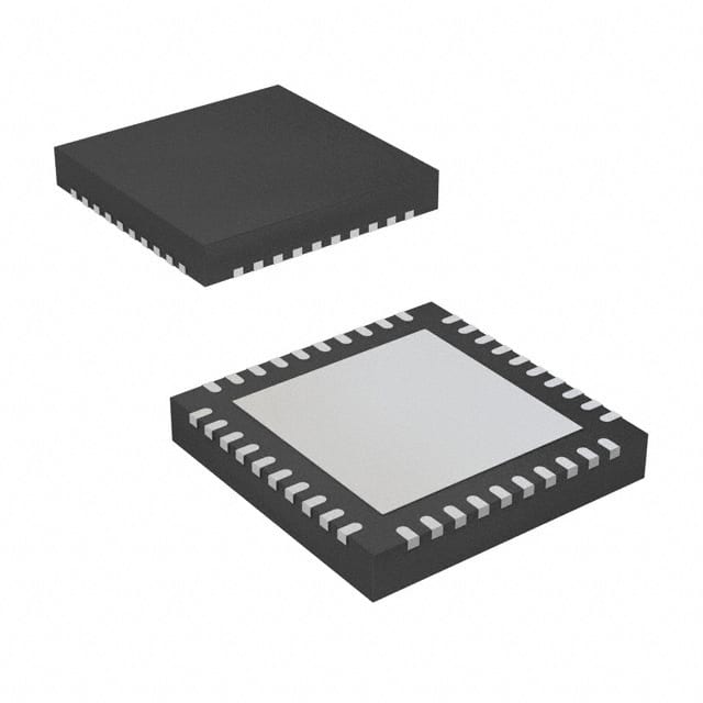
onsemi NCV8855BMNR2G
- Part No.:
- NCV8855BMNR2G
- Manufacturer:
- onsemi
- Category:
- Voltage Regulators - Linear + Switching
- Package:
- 40-VFQFN Exposed Pad
- Datasheet:
-
 NCV8855BMNR2G.pdf
- Description:
- IC REG QD BUCK/LNR 170KHZ 40QFN
- Quantity:
- Payment:

- Shipping:

Inventory:2,249
Please send an inquiry. Send us your inquiry, and we will respond immediately.
Product details
Overview
NCV8855BMNR2G from onsemi is an automotive-grade quad-output system power supply IC integrating a 2 A high-side load switch, one SMPS buck controller, one 2.5 A SMPS buck regulator with internal 300 mΩ NMOS, and two LDO controllers - all operating from 9–18 V input. It powers tuner, CD logic, audio processor, TFT display, flash memory, and CAN transceivers in car radios and instrument clusters.
For engineers reviewing the NCV8855BMNR2G datasheet, pinout, applications, or equivalent options, key selection considerations include its 170 kHz fixed switching frequency with SYNC capability, thermal warning flag (HOT_FLG), independent enable pins (SYS_EN/LDO_EN/HS_EN), and integrated current-sense protection across all outputs.
Technical Context
The NCV8855BMNR2G implements voltage-mode control for both SMPS channels, with dedicated COMP1/COMP2 error amplifier outputs and external compensation via SW_FB1/SW_FB2. Its SMPS1 uses external high-side/low-side NMOS FETs, while SMPS2 integrates a 300 mΩ NMOS switch rated for 2.5 A continuous output.
Each LDO controller drives external P-channel MOSFET pass devices with adjustable output voltage, current limiting (90–130 mV sense threshold), short-circuit protection, and thermal monitoring. The high-side switch features programmable current limit (2.0–3.64 A), overvoltage clamping (15.4–16.6 V), and latched shutdown on sustained overload.
Key Specifications
| Parameter | Value and Actual Design Meaning |
|---|---|
| VIN Range | 9.0 V to 18.0 V - supports full automotive battery range including cold crank (9 V) and load dump (18 V) |
| SMPS1 Type | External-FET buck controller - requires external high-side/low-side NMOS; enables flexible power stage design up to 5 A |
| SMPS2 Output | 2.5 A integrated buck regulator - includes internal 300 mΩ NMOS switch; eliminates need for external power FETs |
| LDO Controllers | Two independent P-MOSFET drivers - support adjustable output voltages (e.g., 3.3 V, 8.5 V) with current limit and short-circuit protection |
| High-Side Switch | 2 A integrated NMOS switch - provides controlled power delivery to CD/tape mechanisms, antennas, or displays with overvoltage clamping |
| Switching Frequency | 170 kHz (±15.3 kHz) - fixed internal oscillator with SYNC pin for external clock synchronization to avoid EMI bands |
| Thermal Monitoring | HOT_FLG pin + dual thermal warning thresholds (TWARN1/TWARN2 = 140–160 °C) - enables early system-level thermal mitigation before shutdown |
Pinout & Package
NCV8855BMNR2G is housed in a 40-pin QFN package (6 mm × 6 mm, MN suffix, Case 488AR) with exposed thermal pad (EP) connected to PCB ground for enhanced thermal dissipation (RJA = 36 °C/W).
| Pin/Terminal | Circuit Role | Design Meaning |
|---|---|---|
| SYS_EN (Pin 5) | Main system enable input | Logic-high (>2.0 V) activates DRV_VPP and 5V_IC rails; floating or low places IC in ultra-low-IQ shutdown (<500 nA) |
| LDO_EN (Pin 6) | LDO controllers enable input | Independent control of both LDOs; only functional when SYS_EN is high; internal pull-down disables LDOs by default |
| HS_EN (Pin 7) | High-side switch enable input | Directly controls HSS activation; allows independent sequencing of display/antenna power relative to core supplies |
| HOT_FLG (Pin 8) | Thermal warning flag output | Open-drain signal pulled low when junction temperature exceeds TWARN1/TWARN2 (140–160 °C); enables preemptive fan control or load shedding |
| DRV_VPP (Pin 22) | Internal 7.2 V gate driver rail | Supplies SMPS1/SMPS2 gate drivers; requires 1 µF ceramic bypass to AGND; UVLO at 4.0–4.7 V ensures robust gate drive during brownout |
| 5V_IC (Pin 35) | Internal 5 V logic supply | Powers internal logic, references, and comparators; 10–50 mA current limit; 4.8–5.2 V regulation ensures stable digital operation |
| DRAIL (Pin 36) | Internal 4.2 V auxiliary rail | Provides bias for analog blocks; bypassed with 0.1 µF capacitor; supports low-noise reference generation |
| SYNC (Pin 4) | Oscillator synchronization input | Accepts external clock (190–255 kHz) to align switching edges; reduces EMI in multi-rail systems; 50 ns minimum pulse width required |
Key Features
| Feature | Design Value |
|---|---|
| Quad-output architecture | Combines SMPS controller, SMPS regulator, two LDO controllers, and high-side switch - reduces BOM count and board space in automotive infotainment systems |
| Independent enable logic | SYS_EN, LDO_EN, and HS_EN allow precise power sequencing - critical for avoiding latch-up in multi-rail subsystems like radio head units |
| Integrated current sensing | OCSET (SMPS1), ISNS1+/ISNS1− (LDO1), ISNS2+/ISNS2− (LDO2), and HS_S (HSS) provide per-rail current monitoring without external sense resistors |
| Automotive transient compliance | Meets ES-XW7T-1A278-AB Test Pulse G - withstands 45 V peak transients on sensitive pins (VIN, OCSET, ISNSx) under loaded conditions |
| Thermal fault management | Dual thermal monitors (TMON_HSS and TMON_SW) with separate warning/shutdown thresholds - enables differentiated response for switch vs. regulator thermal events |
Applications
| Automotive Radio Power Management | Instrument Cluster Power Delivery |
|---|---|
Use Scenario: Supplies regulated power to tuner, CD logic, audio DSP, and display backlight in OEM car radios. IC Role / Device Role / Timing Role: Quad-output PMIC providing 5 V (audio processor), 3.3 V (tuner logic), 8.5 V (CD mechanism), and switched 12 V (antenna/display) with independent enable control. Use Value: Eliminates need for four discrete regulators; enables synchronized soft-start and thermal-aware shutdown during overtemperature events. | Use Scenario: Powers graphics LCD, flash memory, microcontroller, and CAN transceivers in digital instrument clusters. IC Role / Device Role / Timing Role: Delivers 3.3 V (MCU core), 5 V (CAN PHY), 8.5 V (TFT gate drivers), and switched 12 V (backlight dimming) with overvoltage clamping during load dump. Use Value: Integrated HSS limits TFT display current during battery overvoltage (18.5 V trip), preventing damage without external crowbar circuitry. |
| Driver Information System (DIS) | Automotive Infotainment Head Unit |
Use Scenario: Manages power to HUD projection module, ambient lighting control, and vehicle data interface in premium DIS platforms. IC Role / Device Role / Timing Role: Uses LDO controllers to generate precision 3.3 V/5 V rails for sensor interfaces and SMPS2 to drive 2.5 A display backlight LED string. Use Value: Adjustable LDO feedback (LR_FB1/LR_FB2) allows fine-tuning of output voltages to match specific sensor or display requirements. | Use Scenario: Serves as primary power hub in Android Auto/Apple CarPlay head units requiring multiple isolated, sequenced rails. IC Role / Device Role / Timing Role: Coordinates startup of SMPS1 (processor core), SMPS2 (memory), LDO1 (USB PHY), and HSS (touchscreen controller) via independent enable pins. Use Value: 170 kHz switching with SYNC pin enables EMI reduction through spread-spectrum alignment with other system clocks. |
Equivalent & Alternatives
The following parts are listed as comparable options for similar automotive multi-rail power management applications.
| Alternative Part | Technical Difference | Application Difference | Selection Advice |
|---|---|---|---|
| MPQ4333-AEC1 | Triple-output buck converter (no LDO controllers or HSS); 3.5 A per channel; 2.2 MHz switching; no thermal warning flag | Requires external LDOs and high-side switch for full functionality; better suited for compact, high-frequency designs where size > feature count | Select when higher switching frequency and smaller magnetics are prioritized over integrated protection and sequencing flexibility |
| TPS65381A-Q1 | Triple-buck + dual-LDO PMIC; includes watchdog timer and SPI interface; no integrated HSS; 1.2 MHz switching | Lacks high-side switch - needs external FET for antenna/display control; adds diagnostics but increases software overhead | Select when system-level safety monitoring (ASIL-B) and programmable fault response are required over hardware-based thermal flagging |
Compared with MPQ4333-AEC1 and TPS65381A-Q1, the NCV8855BMNR2G offers unique integration of HSS + dual LDO controllers + buck controller + buck regulator in one package, enabling simpler layout and deterministic thermal response via HOT_FLG - critical for cost-sensitive, ASIL-A automotive modules without MCU supervision.
Availability
NCV8855BMNR2G is available at Aetrix Electronics and suitable for automotive radio, instrument cluster, and driver information system applications requiring stable component supply across extended temperature ranges (−40°C to +105°C ambient) and long product lifecycles.
Supply support for NCV8855BMNR2G includes scheduled delivery planning, volume procurement assistance, BOM continuity management, traceable sourcing, and lifecycle availability coordination for OEM customers, industrial embedded developers, connected-device designers, and electronics production programs.
Manufacturer
onsemi is a global semiconductor leader focused on energy-efficient innovation for automotive, industrial, cloud, medical, and IoT applications - delivering high-reliability components meeting AEC-Q100 and ISO/TS 16949 standards.
The NCV8855BMNR2G belongs to onsemi's automotive power management IC portfolio, designed specifically to consolidate power delivery in infotainment and digital cockpit systems while meeting stringent EMC, thermal, and functional safety requirements.
FAQ
What is the maximum output current supported by the integrated high-side switch in the NCV8855BMNR2G?
The NCV8855BMNR2G integrated high-side switch supports a peak current limit of 2.00–3.64 A (typical 2.80 A) with latched shutdown on sustained overload. Its RDS(on) is 233–442 mΩ at VGS = 8 V, resulting in ≤442 mV dropout at 1 A load - suitable for driving CD/tape mechanisms, electric antennas, or TFT display backlights in automotive environments.
Does the NCV8855BMNR2G require external MOSFETs for all its power outputs?
No. The NCV8855BMNR2G integrates a 300 mΩ NMOS switch for SMPS2 (2.5 A regulator), eliminating external FETs for that rail. However, SMPS1 is a controller only and requires external high-side/low-side NMOS FETs. Both LDO controllers drive external P-channel MOSFET pass devices, and the high-side switch uses its internal NMOS - so only SMPS1 mandates external power FETs.
How does thermal management work in the NCV8855BMNR2G, and what role does the HOT_FLG pin play?
The NCV8855BMNR2G features dual thermal monitors: TMON_HSS (for high-side switch junction) and TMON_SW (for SMPS2 internal MOSFET). Each has independent warning (TWARN1/TWARN2 = 140–160 °C) and shutdown (TSD1/TSD2 = 160–180 °C) thresholds. The open-drain HOT_FLG pin pulls low when either monitor exceeds its warning threshold - enabling immediate system-level action (e.g., reduce display brightness) before thermal shutdown occurs.
Can the NCV8855BMNR2G be synchronized to an external clock, and what is the valid frequency range?
Yes. The NCV8855BMNR2G SYNC pin accepts an external clock signal to synchronize its internal 170 kHz oscillator. Valid synchronization range is 190–255 kHz, with 50 ns minimum HIGH/LOW pulse width. Synchronization delay is 200–400 ns to SMPS1 (on falling edge) and SMPS2 (on rising edge), allowing precise phase alignment in multi-PMIC systems to minimize conducted EMI.
What are the key differences between the SMPS1 and SMPS2 sections of the NCV8855BMNR2G?
SMPS1 is a controller-only buck stage requiring external high-side/low-side NMOS FETs and supporting adjustable current limit via OCSET resistor. SMPS2 is a fully integrated 2.5 A buck regulator with internal 300 mΩ NMOS switch, fixed current limit (2.5–4.2 A), and no OCSET pin. Both use voltage-mode control and share the same 170 kHz base frequency, but SMPS2 simplifies design for medium-power rails where external FETs are undesirable.
NCV8855BMNR2G Specifications
- Product attributes
- Attribute value
- Manufacturer:
- onsemi
- Series:
- -
- Package/Case:
- 40-VFQFN Exposed Pad
- Packaging:
- Tape & Reel (TR)
- Product Status:
- Obsolete
- Topology:
- Step-Down (Buck) (2), Linear (LDO) (2)
- Number of Outputs:
- 4
- Frequency - Switching:
- 170kHz
- Voltage/Current - Output 1:
- Controller
- Voltage/Current - Output 2:
- Adjustable, 2.5A
- Voltage/Current - Output 3:
- Controller
- w/LED Driver:
- No
- w/Supervisor:
- No
- w/Sequencer:
- Yes
- Voltage - Supply:
- 9V ~ 18V
- Operating Temperature:
- -40°C ~ 105°C
- Grade:
- Automotive
- Qualification:
- -
- Mounting Type:
- Surface Mount
- Supplier Device Package:
- 40-QFN (6x6)
NCV8855BMNR2G FAQ
1.How can I place an order for NCV8855BMNR2G through Aetrix?
Please submit a Request for Quotation (RFQ) for NCV8855BMNR2G on Aetrix. Our sales agent will provide a competitive quotation and guide you through the order confirmation once you accept the terms.
2.Are the price and stock information for NCV8855BMNR2G reliable?
The price and inventory of NCV8855BMNR2G are updated periodically and may fluctuate due to market conditions. Stock and pricing data are typically refreshed every 24 hours. Quotation validity for NCV8855BMNR2G is usually 5 days.
3.What payment methods are accepted for NCV8855BMNR2G?
We accept Wire Transfer, PayPal, Credit Card, Western Union, MoneyGram, and Escrow for NCV8855BMNR2G transactions.
Note: Certain payment methods may incur a processing fee.
4.How is shipping managed for NCV8855BMNR2G?
NCV8855BMNR2G orders can be shipped via leading logistics carriers, including DHL, UPS, FedEx, TNT, or Registered Mail.
Once your NCV8855BMNR2G order is processed, you will receive an email with the shipment details and tracking number.
Note: Tracking information may take up to 24 hours to appear. Express delivery typically takes 3–5 business days.
5.How can I obtain technical support or documentation for NCV8855BMNR2G?
For technical support, including NCV8855BMNR2G datasheets, pinout diagrams, or application guidance, please contact our engineering support team. They can provide detailed documentation and assistance for your NCV8855BMNR2G requirements.
6.How does Aetrix verify that NCV8855BMNR2G is sourced from the original manufacturer or authorized distributors?
All NCV8855BMNR2G products on Aetrix are procured from qualified distributors and authorized channels. Our dedicated quality assurance team conducts strict verification, including traceability checks and, if necessary, third-party testing. This ensures that NCV8855BMNR2G meets industry standards.
7.What is the process for return or replacement of NCV8855BMNR2G?
All NCV8855BMNR2G units undergo pre-shipment inspection (PSI). If there is an issue with NCV8855BMNR2G, returns or replacements are accepted under the following conditions:
1.Quantity discrepancies, incorrect items, or visible external defects (such as breakage or corrosion), acknowledged by Aetrix.
2.The issue is reported within 90 days of delivery.
3.The NCV8855BMNR2G part is unused and in its original packaging.
Return procedure for NCV8855BMNR2G:
1.Submit a request within 90 days.
2.Obtain a Return Material Authorization (RMA) from Aetrix.
NCV8855BMNR2G Tags

-
TPS6521905RHBR
Texas Instruments
-
MIC3385YHL-TR
Microchip Technology
-
A4402ELPTR-T
Allegro MicroSystems

-
LM26480SQ-AA/NOPB
Texas Instruments
-
A4402KLPTR-T
Allegro MicroSystems
-
BD71847AMWV-E2
ROHM Semiconductor
-
ADP5040ACPZ-1-R7
Analog Devices Inc.
-
LT3048IDC#TRPBF
Analog Devices Inc.
-
ADP5037ACPZ-R7
Analog Devices Inc.

-
XRP7714ILB-F
MaxLinear, Inc.
-
LTC3260EDE#TRPBF
Analog Devices Inc.
-
LTC3260EMSE#PBF
Analog Devices Inc.
Tech Hub

Counterfeit components can hide behind convincing markings and passing basic function tests. This engineering reference covers source traceability, external inspection, X-ray, XRF, electrical testing, …

A practical engineering and sourcing framework covering lifecycle verification, lifetime-buy calculations, replacement qualification, supplier checks and counterfeit-risk controls.

TTL and CMOS logic families differ in thresholds, loading, output drive, power and timing. This engineering guide compares 74HC and 74HCT, calculates noise margins and checks 3.3 V/5 V compatibility.

A practical engineering guide to 3.3V and 5V logic compatibility, input thresholds, resistor dividers, translator ICs, MOSFET level shifting, I2C pull-ups, timing limits and power-sequencing risks.

The 74HC595 uses push-pull logic outputs, while the TPIC6B595 uses 50 V open-drain DMOS sinks for higher-power loads. This guide compares timing, current limits, 3.3 V interfacing, load wiring, thermal…

The 74HC595 converts serial data into eight stable parallel outputs. This guide covers pin functions, shift and storage timing, OE and MR behavior, drive-current limits, cascading, voltage compatibilit…

A technical comparison of level-sensitive latches and edge-triggered flip-flops, covering timing windows, setup and hold limits, master–slave operation, time borrowing, race-through, HDL inference and…

A D latch stores one bit while Enable controls when data can pass. This reference covers gate-level operation, truth tables, transparency, setup and hold timing, LE versus OE, common ICs and practical …

An SR latch stores one bit through cross-coupled feedback. This engineering reference covers NOR and NAND implementations, truth tables, forbidden-state recovery, gated operation, switch debouncing, fa…

Latch circuits retain one bit through feedback. This technical reference covers SR and D latches, truth tables, transparency, timing limits, latch-versus-flip-flop behavior, applications and common log…


