
 My Inquiry
 My Account


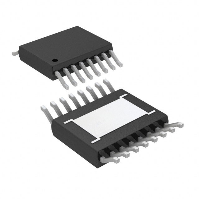
onsemi NCV8881PWR2G
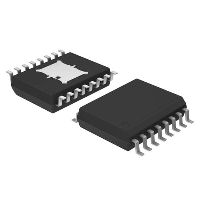
- Part No.:
- NCV8881PWR2G
- Manufacturer:
- onsemi
- Category:
- Voltage Regulators - Linear + Switching
- Package:
- 16-SOIC (0.295", 7.50mm Width) Exposed Pad
- Datasheet:
-
 NCV8881PWR2G.pdf
- Description:
- IC REG TRIPLE BUCK/LINEAR 16SOIC
- Quantity:
- Payment:

- Shipping:

Inventory:3,808
Please send an inquiry. Send us your inquiry, and we will respond immediately.
Product details
Overview
NCV8881PWR2G from onsemi is an automotive-grade buck regulator with integrated watchdog, dual LDOs (5 V/100 mA and 8.5 V/40 mA), and SMPS output undervoltage monitoring. It delivers 1.5 A switching output from 5–19 V input, withstands 40 V load dump, and operates across −40 °C to +150 °C junction temperature - designed for infotainment power rails and CPU supervision in vehicle battery-connected systems.
For engineers reviewing the NCV8881PWR2G datasheet, pinout, applications, or equivalent options, key selection criteria include programmable SMPS frequency (154–850 kHz), resistor-programmable watchdog delay (48–1300 ms), VIN UVLO/ovv thresholds (5.6 V start / 20 V overvoltage stop), 2% reference tolerance, and SO-16W EP package thermal performance (RJA = 55 °C/W).
Technical Context
The NCV8881PWR2G integrates a voltage-mode buck controller with internal 1.5 A N-channel power switch, two independent LDOs sharing a single LDOMON fault flag, and a resistor-programmable watchdog timer that also monitors SMPS regulation status. Its enable input features user-configurable hysteresis via external resistor divider, and the IGNBUF open-drain output replicates EN state for ignition signaling.
SMPS operation supports resistor-programmed or externally synchronized switching (160–600 kHz), with internal soft-start (3–7 ms), cycle-by-cycle current limit (1.75–3 A), short-circuit detection (70–85% VREF), and bootstrap diode integration. All regulators include thermal shutdown (160–180 °C), input overvoltage protection, and LDO UVLO with 2% hysteresis.
Key Specifications
| Parameter | Value and Actual Design Meaning |
|---|---|
| SMPS Output Current | 1.5 A continuous - sufficient for powering microcontrollers, audio codecs, or vision system SoCs in automotive ECUs. |
| LDO Outputs | 5.0 V / 100 mA and 8.5 V / 40 mA - supply logic rails and gate drive for external high-side switches or analog sensors. |
| Input Voltage Range | 5 V to 19 V operating; withstands 40 V load dump - meets ISO 7637-2 Pulse 5a requirements for 12 V automotive systems. |
| Reference Voltage Tolerance | ±2% over −40 °C to +150 °C - ensures stable SMPS output regulation under extreme under-hood thermal conditions. |
| Watchdog Delay Range | 48 ms to 1300 ms (resistor-programmable via RDLY pin) - configurable to match CPU reset timeout requirements without firmware changes. |
| Thermal Shutdown Threshold | 160–180 °C with 35 °C hysteresis - prevents latch-up during sustained overload while enabling safe recovery after cooling. |
| Package Thermal Resistance | RJA = 55 °C/W (1 in² copper) - enables reliable 1.5 A operation at +105 °C ambient with standard PCB layout. |
Pinout & Package
NCV8881PWR2G uses the SO-16W EP (Case 751AG) package with exposed thermal pad. The 16-pin wide-body SOIC includes integrated heat dissipation path via soldered exposed pad, supporting high-power automotive operation.
| Pin/Terminal | Circuit Role | Design Meaning |
|---|---|---|
| 1 - IGNBUF | Open-drain ignition buffer output | Replicates EN logic state; requires external pull-up - used for engine control unit (ECU) wake-up signaling or ignition status indication. |
| 2 - WDI | Watchdog input | CMOS-compatible pulse input; falling-edge period must be < programmed watchdog delay - detects CPU lockup or firmware hang. |
| 3 - RDLY | Watchdog/POR delay programming | Resistor-to-ground sets POR, boot, and watchdog delays - enables hardware-timed reset sequencing without software dependency. |
| 4 - RESB | Open-drain reset output | Pulled low on VIN UV/OV, SMPS out-of-regulation, thermal shutdown, or invalid WDI - drives CPU reset line directly. |
| 5 - EN | Logic-enable input | Hysteresis programmable via external divider; latches once high - allows robust start-up in noisy automotive environments. |
| 6 - SYNC | Switching frequency synchronization | Accepts external clock (160–600 kHz); overrides ROSC resistor setting - enables EMI reduction via spread-spectrum or fixed-frequency coordination. |
| 7 - ROSC | Oscillator frequency programming | Resistor-to-ground sets SMPS frequency (154–850 kHz) - balances efficiency, size, and EMI for specific inductor/capacitor selection. |
| 8 - GND | Power ground reference | Main return path for SMPS, LDOs, and logic - must connect to low-impedance ground plane and exposed pad for thermal integrity. |
| 9 - COMP | Error amplifier compensation node | External RC network tailors transient response and stability - critical for maintaining regulation during rapid load steps (e.g., audio amplifier burst). |
| 10 - FB | SMPS feedback input | Monitors output voltage; triggers RESB low if <89% or >99% of 0.8 V reference - provides precise undervoltage/overvoltage fault detection. |
| 11 - BST | Bootstrap supply for high-side switch | Drives gate above VIN; 0.1 µF ceramic cap to SW required - ensures low RDS(on) and high efficiency in buck topology. |
| 12 - SW | Switching node | Connects to inductor and freewheeling diode cathode - high dV/dt node requiring tight layout and minimized trace length. |
| 13 - VIN | Main input supply | Accepts 5–19 V; withstands 40 V transients - connects directly to vehicle battery via input filter capacitor (4.7 µF typical). |
| 14 - 8P5 | 8.5 V LDO output | Regulated gate drive supply; 40 mA max - powers external high-side MOSFET drivers or analog front-ends requiring stable bias. |
| 15 - LDOMON | LDO fault monitor output | Open-drain low if either 5P0 or 8P5 is out-of-regulation - simplifies system-level power health monitoring with single GPIO. |
| 16 - 5P0 | 5.0 V LDO output | 100 mA regulated supply - powers microcontroller cores, CAN transceivers, or sensor interfaces in safety-critical subsystems. |
Key Features
| Feature | Design Value |
|---|---|
| Integrated watchdog with resistor-programmable delay | Hardware-enforced CPU reset timing (48–1300 ms) eliminates firmware dependency for fail-safe recovery in ADAS and infotainment. |
| Dual LDOs with shared LDOMON fault flag | Reduces system GPIO count by consolidating 5 V and 8.5 V regulation monitoring into one open-drain signal. |
| SMPS with internal power switch and bootstrap diode | Eliminates external high-side driver and bootstrap diode - reduces BOM count and PCB area in space-constrained automotive modules. |
| Automotive-grade protection suite | Includes VIN UVLO (5.6 V start), OV shutdown (20 V stop), thermal shutdown (160–180 °C), and SMPS short-circuit detection - meets AEC-Q100 stress requirements. |
| Programmable enable hysteresis | External resistor divider configures EN activation/deactivation thresholds - prevents oscillation during slow-rising battery voltage (e.g., cold-crank conditions). |
| Exposed-pad SO-16W EP package | Thermal resistance RJA = 55 °C/W enables full 1.5 A output at +105 °C ambient - suitable for under-dash and engine bay mounting. |
Applications
| Infotainment Head Unit Power | ADAS Camera Module Supply |
|---|---|
|
Use Scenario: Powering DSP, display controller, and USB PHY in a vehicle head unit with battery input subject to load dump and cold-crank. IC Role / Device Role / Timing Role: Primary SMPS (1.5 A @ 3.3 V or 5 V) + auxiliary LDOs (5 V/100 mA, 8.5 V/40 mA) + watchdog supervision. Use Value: Single-chip solution replaces discrete buck + dual LDO + reset IC, reducing component count by ≥4 while meeting ISO 16750-2 transient immunity. |
Use Scenario: Supplying image sensor, ISP, and serializer in a rear-view camera module mounted near exhaust or engine compartment. IC Role / Device Role / Timing Role: Regulated 5 V rail for sensor interface + 8.5 V gate drive for external FET + watchdog monitoring of ISP firmware. Use Value: 150 °C junction rating and 40 V load dump tolerance ensure uninterrupted operation in high-temperature zones without derating. |
| Instrument Cluster Microcontroller Supply | Body Control Module (BCM) Subsystem |
|
Use Scenario: Providing clean, monitored 5 V supply to MCU and CAN transceiver in digital instrument cluster with ignition-controlled enable. IC Role / Device Role / Timing Role: LDO output (5P0) powers MCU core; IGNBUF mirrors EN for ignition status; RESB drives MCU reset. Use Value: Integrated IGNBUF eliminates need for external level-shifter; EN hysteresis prevents false resets during battery voltage sag during cranking. |
Use Scenario: Powering door module MCU, LIN transceiver, and LED drivers in BCM where space and thermal management are constrained. IC Role / Device Role / Timing Role: SMPS supplies 3.3 V logic rail; 8.5 V LDO drives high-side LED switch; LDOMON flags any LDO fault. Use Value: Dual-fault reporting (RESB for SMPS/system faults, LDOMON for LDO-specific faults) enables granular diagnostics per ISO 26262 ASIL-B compliance. |
Equivalent & Alternatives
The following parts are listed as comparable options for similar automotive power management applications.
| Alternative Part | Technical Difference | Application Difference | Selection Advice |
|---|---|---|---|
| TPS65381A-Q1 | Triple-output PMIC (2 buck + 1 LDO); no integrated watchdog; requires external reset IC for CPU supervision. | Targeted at multi-rail MCU power (e.g., Hercules TMS570); lacks hardware watchdog and LDO fault monitoring. | Select when needing three independent regulated outputs but willing to add external watchdog and fault logic. |
| MAX20090ATPA/VY+ | Single-buck + dual-LDO with watchdog; 2.2 A SMPS output; supports 3.3/5/8.5 V LDOs; no LDOMON shared fault flag. | Higher SMPS current capability; broader LDO voltage options; lacks consolidated LDO fault reporting pin. | Select when higher 2.2 A SMPS current is required and separate LDO fault monitoring is acceptable. |
Compared with TPS65381A-Q1 and MAX20090ATPA/VY+, the NCV8881PWR2G uniquely combines 1.5 A buck, dual LDOs, hardware watchdog, and shared LDOMON fault flag in a single SO-16W EP package - optimizing BOM count, diagnostic granularity, and thermal performance for cost-sensitive automotive subsystems.
Availability
NCV8881PWR2G is available at Aetrix Electronics and suitable for automotive infotainment, ADAS camera modules, digital instrument clusters, and body control units requiring stable component supply under AEC-Q100 stress conditions and long-term automotive lifecycle support.
Supply support for NCV8881PWR2G includes scheduled delivery planning, volume procurement assistance, BOM continuity management, traceable sourcing, and lifecycle availability coordination for OEM customers, industrial embedded developers, connected-device designers, and electronics production programs.
Manufacturer
onsemi is a global semiconductor leader focused on energy-efficient innovation, delivering silicon solutions for automotive, industrial, cloud, and IoT applications with strong AEC-Q100 and IATF 16949 compliance.
The NCV8881PWR2G belongs to onsemi's automotive power management portfolio, engineered specifically for battery-connected systems requiring integrated regulation, supervision, and transient resilience in harsh vehicle environments.
FAQ
What is the maximum input voltage the NCV8881PWR2G can withstand during load dump events?
The NCV8881PWR2G is rated to withstand 40 V input transients, complying with ISO 7637-2 Pulse 5a for 12 V automotive systems. Its internal overvoltage protection activates at 19–21 V (typical 20 V stop threshold), pulling RESB low and shutting down all regulators until VIN drops below the restart threshold of 18–19.2 V. This ensures survival during alternator load dump without external TVS clamping in many designs.
How does the NCV8881PWR2G's watchdog function interact with the SMPS output regulation status?
The NCV8881PWR2G's RESB output goes low not only when the WDI pulse period exceeds the programmed watchdog delay, but also when the SMPS output falls outside regulation (FB < 89% or > 99% of 0.8 V reference). This dual-trigger behavior means RESB serves as both CPU reset and SMPS fault indicator - eliminating need for separate power-good monitoring circuitry in safety-critical applications.
Can the NCV8881PWR2G's SMPS output voltage be adjusted below 3.3 V?
Yes - the NCV8881PWR2G's SMPS output is programmable down to 0.8 V using the FB pin and external resistor divider, per the formula VOUT = 0.8 V × (1 + R1/R2). While typical automotive applications use 3.3 V or 5 V outputs, this flexibility supports low-voltage SoCs or custom logic rails. The 2% reference tolerance ensures ±2.4% accuracy at 3.3 V output across temperature.
What thermal performance can be expected from the NCV8881PWR2G in a standard 1 oz. copper PCB layout?
In a standard 3" × 3" FR4 board with 1 in² (645 mm²) copper pour connected to the exposed pad, the NCV8881PWR2G achieves RJA = 55 °C/W. At 1.5 A load and 13.2 V input, typical power dissipation is ~1.2 W, resulting in ~66 °C junction rise above ambient - well within the −40 °C to +150 °C operating range even at +85 °C ambient. No heatsink is required for most automotive applications.
Is the NCV8881PWR2G pin-compatible with other devices in the NCV88xx family?
No - the NCV8881PWR2G has a unique pinout optimized for its integrated watchdog, dual LDOs, and LDOMON functionality. Devices like NCV8853 or NCV8854 offer different feature sets (e.g., no watchdog, single LDO) and distinct pin assignments. PCB layout must be designed specifically for NCV8881PWR2G; migration requires schematic and layout revision.
NCV8881PWR2G Specifications
- Product attributes
- Attribute value
- Manufacturer:
- onsemi
- Series:
- -
- Package/Case:
- 16-SOIC (0.295", 7.50mm Width) Exposed Pad
- Packaging:
- Tape & Reel (TR)
- Product Status:
- Obsolete
- Topology:
- Step-Down (Buck) (1), Linear (LDO) (2)
- Number of Outputs:
- 3
- Frequency - Switching:
- 170kHz
- Voltage/Current - Output 1:
- 3.3V ~ 8V, 1.5A
- Voltage/Current - Output 2:
- 5V, 100mA
- Voltage/Current - Output 3:
- 8.5V, 40mA
- w/LED Driver:
- No
- w/Supervisor:
- No
- w/Sequencer:
- No
- Voltage - Supply:
- 5V ~ 19V
- Operating Temperature:
- -40°C ~ 150°C
- Grade:
- Automotive
- Qualification:
- -
- Mounting Type:
- Surface Mount
- Supplier Device Package:
- 16-SOIC
NCV8881PWR2G FAQ
1.How can I place an order for NCV8881PWR2G through Aetrix?
Please submit a Request for Quotation (RFQ) for NCV8881PWR2G on Aetrix. Our sales agent will provide a competitive quotation and guide you through the order confirmation once you accept the terms.
2.Are the price and stock information for NCV8881PWR2G reliable?
The price and inventory of NCV8881PWR2G are updated periodically and may fluctuate due to market conditions. Stock and pricing data are typically refreshed every 24 hours. Quotation validity for NCV8881PWR2G is usually 5 days.
3.What payment methods are accepted for NCV8881PWR2G?
We accept Wire Transfer, PayPal, Credit Card, Western Union, MoneyGram, and Escrow for NCV8881PWR2G transactions.
Note: Certain payment methods may incur a processing fee.
4.How is shipping managed for NCV8881PWR2G?
NCV8881PWR2G orders can be shipped via leading logistics carriers, including DHL, UPS, FedEx, TNT, or Registered Mail.
Once your NCV8881PWR2G order is processed, you will receive an email with the shipment details and tracking number.
Note: Tracking information may take up to 24 hours to appear. Express delivery typically takes 3–5 business days.
5.How can I obtain technical support or documentation for NCV8881PWR2G?
For technical support, including NCV8881PWR2G datasheets, pinout diagrams, or application guidance, please contact our engineering support team. They can provide detailed documentation and assistance for your NCV8881PWR2G requirements.
6.How does Aetrix verify that NCV8881PWR2G is sourced from the original manufacturer or authorized distributors?
All NCV8881PWR2G products on Aetrix are procured from qualified distributors and authorized channels. Our dedicated quality assurance team conducts strict verification, including traceability checks and, if necessary, third-party testing. This ensures that NCV8881PWR2G meets industry standards.
7.What is the process for return or replacement of NCV8881PWR2G?
All NCV8881PWR2G units undergo pre-shipment inspection (PSI). If there is an issue with NCV8881PWR2G, returns or replacements are accepted under the following conditions:
1.Quantity discrepancies, incorrect items, or visible external defects (such as breakage or corrosion), acknowledged by Aetrix.
2.The issue is reported within 90 days of delivery.
3.The NCV8881PWR2G part is unused and in its original packaging.
Return procedure for NCV8881PWR2G:
1.Submit a request within 90 days.
2.Obtain a Return Material Authorization (RMA) from Aetrix.
NCV8881PWR2G Tags

-
TPS6521905RHBR
Texas Instruments
-
MIC3385YHL-TR
Microchip Technology
-
A4402ELPTR-T
Allegro MicroSystems

-
LM26480SQ-AA/NOPB
Texas Instruments
-
A4402KLPTR-T
Allegro MicroSystems
-
BD71847AMWV-E2
ROHM Semiconductor
-
ADP5040ACPZ-1-R7
Analog Devices Inc.
-
LT3048IDC#TRPBF
Analog Devices Inc.
-
ADP5037ACPZ-R7
Analog Devices Inc.

-
XRP7714ILB-F
MaxLinear, Inc.
-
LTC3260EDE#TRPBF
Analog Devices Inc.
-
LTC3260EMSE#PBF
Analog Devices Inc.
Tech Hub

Counterfeit components can hide behind convincing markings and passing basic function tests. This engineering reference covers source traceability, external inspection, X-ray, XRF, electrical testing, …

A practical engineering and sourcing framework covering lifecycle verification, lifetime-buy calculations, replacement qualification, supplier checks and counterfeit-risk controls.

TTL and CMOS logic families differ in thresholds, loading, output drive, power and timing. This engineering guide compares 74HC and 74HCT, calculates noise margins and checks 3.3 V/5 V compatibility.

A practical engineering guide to 3.3V and 5V logic compatibility, input thresholds, resistor dividers, translator ICs, MOSFET level shifting, I2C pull-ups, timing limits and power-sequencing risks.

The 74HC595 uses push-pull logic outputs, while the TPIC6B595 uses 50 V open-drain DMOS sinks for higher-power loads. This guide compares timing, current limits, 3.3 V interfacing, load wiring, thermal…

The 74HC595 converts serial data into eight stable parallel outputs. This guide covers pin functions, shift and storage timing, OE and MR behavior, drive-current limits, cascading, voltage compatibilit…

A technical comparison of level-sensitive latches and edge-triggered flip-flops, covering timing windows, setup and hold limits, master–slave operation, time borrowing, race-through, HDL inference and…

A D latch stores one bit while Enable controls when data can pass. This reference covers gate-level operation, truth tables, transparency, setup and hold timing, LE versus OE, common ICs and practical …

An SR latch stores one bit through cross-coupled feedback. This engineering reference covers NOR and NAND implementations, truth tables, forbidden-state recovery, gated operation, switch debouncing, fa…

Latch circuits retain one bit through feedback. This technical reference covers SR and D latches, truth tables, transparency, timing limits, latch-versus-flip-flop behavior, applications and common log…


