
 My Inquiry
 My Account


NXP Semiconductors NE1618DS,112
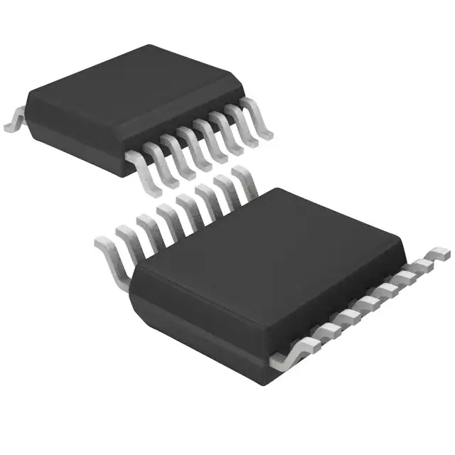
- Part No.:
- NE1618DS,112
- Manufacturer:
- NXP Semiconductors
- Category:
- Analog and Digital Output
- Package:
- 16-SSOP (0.154", 3.90mm Width)
- Datasheet:
-
 NE1618DS,112.pdf
- Description:
- SENSOR DIGITAL 0C-120C 16SSOP
- Quantity:
- Payment:

- Shipping:

Inventory:3,250
Please send an inquiry. Send us your inquiry, and we will respond immediately.
Product details
Overview
NE1618DS,112 from NXP Semiconductors (formerly Philips) is a dual-channel SMBus-compatible temperature monitor IC for microprocessor systems. It measures local on-chip temperature with ±2 °C accuracy and remote diode temperature with ±1.5 °C (1 °C resolution) or ±1.0 °C (0.125 °C resolution), operates from 3.0–3.6 V, draws 80 µA active current, and uses a 16-lead QSOP package. It is deployed in notebook computers and telecom equipment for real-time thermal management.
For engineers reviewing the NE1618DS,112 datasheet, NE1618DS,112 pinout, NE1618DS,112 application, or NE1618DS,112 equivalent, key selection considerations include its dual-sensor architecture, SMBus 2-wire interface timing compliance, programmable over/under-temperature alarm thresholds, extended-mode remote resolution (0.125 °C), and hardware/software standby control via STBY pin and RUN/STOP bit.
Technical Context
The NE1618DS,112 implements a sigma-delta A-to-D converter for local and remote temperature sensing, with automatic conversion rate-dependent mode selection: basic mode (1 °C remote resolution) at ≥2 Hz rates and extended mode (0.125 °C remote resolution) at ≤0.7 Hz rates. Its SMBus slave interface supports nine configurable 7-bit addresses via ADD0/ADD1 pins and includes open-drain SDATA/SCLK with 10 kΩ pull-ups.
It features dedicated registers for local/remote high/low limits (RIHL/RILL/REHL/RELL), status flag reporting (bit 7 = busy), and one-shot conversion triggering (OSHT command 0Fh). Remote sensing requires a diode-connected PNP (e.g., Intel CPU die sensor or 2N3904), with D+ as anode and D– as cathode, and supports extended data reconstruction from RET (8 MSB) and REET (3 LSB) registers.
Key Specifications
| Parameter | Value and Actual Design Meaning |
|---|---|
| Local temp accuracy | ±2 °C over 0–120 °C - enables reliable board-level thermal monitoring without calibration |
| Remote temp accuracy | ±1.0 °C (0.125 °C res.) or ±1.5 °C (1 °C res.) - supports precise die-temperature tracking of CPUs/GPUs |
| Supply voltage | 3.0–3.6 V - compatible with modern low-voltage logic rails and avoids level-shifting overhead |
| Active supply current | 80–270 µA depending on conversion rate - scales with measurement frequency for power-aware designs |
| Standby current | 3 µA typical - enables ultra-low-power thermal supervision during system sleep states |
| SMBus address options | 9 unique 7-bit addresses (via ADD0/ADD1) - allows up to nine NE1618DS,112 devices on one bus |
| Conversion time | 150 ms (basic), 750 ms (extended) - defines minimum interval between valid remote readings |
Pinout & Package
NE1618DS,112 is housed in a 16-lead QSOP (SOT519-1) package, also referenced as SSOP16. Pin 1 is TEST1 (factory use only); pins 7 and 8 are GND; pin 2 is VDD (3.0–3.6 V supply, decoupled with 0.1 µF capacitor); pins 3 and 4 are D+ and D– for remote diode connection (anode to D+, cathode to D–); pins 6 and 10 are ADD1 and ADD0 for address configuration; pin 11 is ALERT (open-drain interrupt); pins 12 and 14 are SDATA and SCLK (SMBus interface); pin 15 is STBY (hardware standby control); all TEST pins (1,5,9,13,16) must be floating or tied to GND.
| Pin/Terminal | Circuit Role | Design Meaning |
|---|---|---|
| VDD (Pin 2) | Positive supply input | Must be decoupled with 0.1 µF capacitor; under-voltage lockout activates below 2.1 V |
| D+ / D– (Pins 3/4) | Remote diode interface | D+ = anode, D– = cathode; accepts discrete transistors (2N3904) or integrated PNP diodes (Intel CPUs) |
| ADD0 / ADD1 (Pins 10/6) | Address configuration inputs | Three-level logic (GND/VDD/NC) sets one of nine SMBus slave addresses; latched at power-up and start-of-conversion |
| STBY (Pin 15) | Hardware standby enable | LOW = disables A-to-D converter and forces <10 µA standby current; HIGH = normal operation |
| ALERT (Pin 11) | Open-drain interrupt output | Asserts LOW when local/remote temp exceeds programmed high/low limits; requires external pull-up |
| SDATA / SCLK (Pins 12/14) | SMBus serial interface | Open-drain signals; require ~10 kΩ pull-ups; support 0–100 kHz clock; no timeout capability |
Key Features
| Feature | Design Value |
|---|---|
| Dual-sensor measurement | Simultaneous local (on-chip) and remote (diode) temperature acquisition with independent limit registers |
| Resolution-selectable remote sensing | Automatically switches between 1 °C (fast rates ≥2 Hz) and 0.125 °C (slow rates ≤0.7 Hz) based on conversion rate register value |
| Programmable alarm thresholds | Independent high/low limits for both channels stored in writable registers (WIHL/WILL/WEHL/WELL) |
| Low-power standby modes | Hardware (STBY pin) and software (RUN/STOP bit) standby options; 3 µA typical quiescent current |
| SMBus-compliant interface | Full 2-wire protocol support including status register (RS), one-shot command (OSHT), and device ID read (RDID) |
Applications
| Desktop Computers | Notebook Computers |
|---|---|
Use Scenario: Real-time CPU and motherboard thermal monitoring during sustained workloads. IC Role / Device Role / Timing Role: Local sensor tracks die temperature; remote sensor monitors VRM or GPU junction via integrated diode. Use Value: Enables dynamic clock throttling and fan speed control using SMBus-accessible 0.125 °C-resolution remote readings. |
Use Scenario: Compact thermal supervision in space-constrained laptop chassis with multiple heat sources. IC Role / Device Role / Timing Role: Measures local ambient PCB temperature and remote battery pack or SSD controller temperature. Use Value: Supports battery safety cutoff and SSD thermal throttling using programmable low-limit alarms and 3 µA standby current. |
| Smart Battery Packs | Telecom Equipment |
Use Scenario: Over-temperature protection for Li-ion cells during fast charging in portable devices. IC Role / Device Role / Timing Role: Remote diode placed on cell tab; local sensor monitors BMS IC junction temperature. Use Value: Provides ±1.0 °C remote accuracy at 0.125 °C resolution to detect early thermal runaway before critical thresholds. |
Use Scenario: Thermal management of line cards and power modules in carrier-grade routers and base stations. IC Role / Device Role / Timing Role: Monitors FPGA die temperature (remote) and board ambient (local) across multiple slots. Use Value: Nine-address SMBus support allows centralized thermal telemetry from up to nine NE1618DS,112 sensors per backplane. |
Equivalent & Alternatives
The following parts are listed as comparable options for similar temperature monitor applications.
| Alternative Part | Technical Difference | Application Difference | Selection Advice |
|---|---|---|---|
| LM94022QDCNTQ1 | Single-channel remote-only sensor; ±0.7 °C accuracy; 1.7–3.6 V supply; I²C interface | Lacks local sensing and SMBus alert functionality; no hardware STBY pin | Choose LM94022QDCNTQ1 only if remote-only monitoring suffices and I²C is preferred over SMBus |
| MAX6642AESA+ | Dual-channel with ±1 °C local/±2 °C remote accuracy; 3–5.5 V supply; SMBus 1.1 compliant | Higher voltage range but lacks extended 0.125 °C resolution mode; no TEST pin constraints | Choose MAX6642AESA+ for broader supply compatibility where 0.125 °C resolution is not required |
Compared with NE1618DS,112, LM94022QDCNTQ1 offers higher remote accuracy but omits local sensing and SMBus alert signaling, while MAX6642AESA+ supports wider voltage operation but sacrifices the precision extended-mode remote measurement essential for CPU die monitoring.
Availability
NE1618DS,112 is available at Aetrix Electronics and suitable for desktop computers, notebook computers, and telecom equipment requiring stable component supply across long-lifecycle industrial deployments.
Supply support for NE1618DS,112 includes scheduled delivery planning, volume procurement assistance, BOM continuity management, traceable sourcing, and lifecycle availability coordination for OEM customers, industrial embedded developers, connected-device designers, and electronics production programs.
Manufacturer
NXP Semiconductors, formerly Philips Semiconductors, is a global leader in high-performance mixed-signal ICs, with expertise in automotive, industrial, and computing applications.
The NE1618DS,112 belongs to NXP's legacy thermal monitoring product line, designed specifically for SMBus-based microprocessor thermal management in cost-sensitive, space-constrained computing platforms.
FAQ
What is the remote temperature sensor requirement for NE1618DS,112?
The NE1618DS,112 requires a diode-connected PNP transistor as the remote sensor, such as the 2N3904 or the integrated PNP diode found on Intel microprocessors. The anode must connect to D+ (Pin 3) and the cathode to D– (Pin 4). The device provides 10 µA and 100 µA current sources for remote sensing, and the diode voltage must remain within 0.25–0.95 V for valid measurement. NE1618DS,112 does not support NTC thermistors or digital sensors.
How does NE1618DS,112 select between basic and extended remote temperature resolution?
NE1618DS,112 automatically selects basic mode (1 °C resolution) when the conversion rate register is set to 05h–07h (2–8 Hz), and extended mode (0.125 °C resolution) when set to 00h–04h (≤0.7 Hz). This selection is hardwired in silicon and cannot be overridden by software. In extended mode, remote temperature data spans two registers: RET (8 MSB) and REET (3 LSB), which must be combined to reconstruct the full 11-bit value. NE1618DS,112 ignores REET in basic mode.
Can NE1618DS,112 operate from a 5 V supply?
No, NE1618DS,112 is specified only for 3.0–3.6 V operation. Although some electrical characteristics (e.g., temperature error) are listed for 5.0 V in the datasheet, these are design guarantees-not operational ratings. Absolute maximum VDD is +6 V, but functional operation outside 3.0–3.6 V violates specification and may cause undefined behavior, inaccurate readings, or accelerated aging. NE1618DS,112 must be powered from a regulated 3.3 V rail with proper 0.1 µF decoupling.
What happens to NE1618DS,112 registers during hardware standby (STBY = LOW)?
When STBY = LOW, NE1618DS,112 enters hardware standby: the A-to-D converter is disabled, conversion stops, and supply current drops to ≤10 µA. All register contents-including temperature readings, limits, configuration, and status-are retained. SMBus communication remains fully functional: registers can be read or written, and ALERT remains responsive to limit violations stored prior to standby. However, no new conversions occur until STBY returns HIGH. NE1618DS,112 does not update RIT, RET, or REET during hardware standby.
Is NE1618DS,112 pin-compatible with NE1617?
No, NE1618DS,112 is not pin-compatible with NE1617. While both are dual-channel SMBus temperature monitors from Philips/NXP, NE1617 uses a 24-pin SOIC package and different pin assignments (e.g., separate ALERT and THERM outputs, no STBY pin). NE1618DS,112 uses a 16-pin QSOP with STBY, ADD0/ADD1, and merged SMBus pins. Board-level replacement requires PCB redesign. NE1618DS,112 replaces NE1617 functionally in enhanced applications but not mechanically.
NE1618DS,112 Specifications
- Product attributes
- Attribute value
- Manufacturer:
- NXP Semiconductors
- Series:
- -
- Package/Case:
- 16-SSOP (0.154", 3.90mm Width)
- Packaging:
- Tube
- Product Status:
- Obsolete
- Sensor Type:
- Digital, Local/Remote
- Sensing Temperature - Local:
- 0°C ~ 120°C
- Sensing Temperature - Remote:
- 0°C ~ 120°C
- Output Type:
- SMBus
- Voltage - Supply:
- 3V ~ 3.6V
- Resolution:
- 8 b
- Features:
- One-Shot, Output Switch, Programmable Limit, Shutdown Mode, Standby Mode
- Accuracy - Highest (Lowest):
- ±1.5°C (±3°C)
- Test Condition:
- 60°C ~ 100°C (0°C ~ 120°C)
- Operating Temperature:
- 0°C ~ 120°C
- Mounting Type:
- Surface Mount
- Grade:
- -
- Qualification:
- -
- Supplier Device Package:
- 16-SSOP
NE1618DS,112 FAQ
1.How can I place an order for NE1618DS,112 through Aetrix?
Please submit a Request for Quotation (RFQ) for NE1618DS,112 on Aetrix. Our sales agent will provide a competitive quotation and guide you through the order confirmation once you accept the terms.
2.Are the price and stock information for NE1618DS,112 reliable?
The price and inventory of NE1618DS,112 are updated periodically and may fluctuate due to market conditions. Stock and pricing data are typically refreshed every 24 hours. Quotation validity for NE1618DS,112 is usually 5 days.
3.What payment methods are accepted for NE1618DS,112?
We accept Wire Transfer, PayPal, Credit Card, Western Union, MoneyGram, and Escrow for NE1618DS,112 transactions.
Note: Certain payment methods may incur a processing fee.
4.How is shipping managed for NE1618DS,112?
NE1618DS,112 orders can be shipped via leading logistics carriers, including DHL, UPS, FedEx, TNT, or Registered Mail.
Once your NE1618DS,112 order is processed, you will receive an email with the shipment details and tracking number.
Note: Tracking information may take up to 24 hours to appear. Express delivery typically takes 3–5 business days.
5.How can I obtain technical support or documentation for NE1618DS,112?
For technical support, including NE1618DS,112 datasheets, pinout diagrams, or application guidance, please contact our engineering support team. They can provide detailed documentation and assistance for your NE1618DS,112 requirements.
6.How does Aetrix verify that NE1618DS,112 is sourced from the original manufacturer or authorized distributors?
All NE1618DS,112 products on Aetrix are procured from qualified distributors and authorized channels. Our dedicated quality assurance team conducts strict verification, including traceability checks and, if necessary, third-party testing. This ensures that NE1618DS,112 meets industry standards.
7.What is the process for return or replacement of NE1618DS,112?
All NE1618DS,112 units undergo pre-shipment inspection (PSI). If there is an issue with NE1618DS,112, returns or replacements are accepted under the following conditions:
1.Quantity discrepancies, incorrect items, or visible external defects (such as breakage or corrosion), acknowledged by Aetrix.
2.The issue is reported within 90 days of delivery.
3.The NE1618DS,112 part is unused and in its original packaging.
Return procedure for NE1618DS,112:
1.Submit a request within 90 days.
2.Obtain a Return Material Authorization (RMA) from Aetrix.
NE1618DS,112 Tags
-
MCP9700T-E/TT
Microchip Technology
-
MCP9700T-E/LT
Microchip Technology
-
MCP9701T-E/TT
Microchip Technology
-
MCP9701T-E/LT
Microchip Technology

-
TMP235A4DBZR
Texas Instruments
-
MCP9700AT-E/TT
Microchip Technology
-
MCP9700AT-E/LT
Microchip Technology
-
MCP9701AT-E/LT
Microchip Technology
-
MCP9701AT-E/TT
Microchip Technology
,TO-226_straightlead.jpg)
-
LM335Z
STMicroelectronics
-
TMP1075NDRLR
Texas Instruments
-
TMP1075DGKR
Texas Instruments
Tech Hub

A practical engineering guide to 3.3V and 5V logic compatibility, input thresholds, resistor dividers, translator ICs, MOSFET level shifting, I2C pull-ups, timing limits and power-sequencing risks.

The 74HC595 uses push-pull logic outputs, while the TPIC6B595 uses 50 V open-drain DMOS sinks for higher-power loads. This guide compares timing, current limits, 3.3 V interfacing, load wiring, thermal…

The 74HC595 converts serial data into eight stable parallel outputs. This guide covers pin functions, shift and storage timing, OE and MR behavior, drive-current limits, cascading, voltage compatibilit…

A technical comparison of level-sensitive latches and edge-triggered flip-flops, covering timing windows, setup and hold limits, master–slave operation, time borrowing, race-through, HDL inference and…

A D latch stores one bit while Enable controls when data can pass. This reference covers gate-level operation, truth tables, transparency, setup and hold timing, LE versus OE, common ICs and practical …

An SR latch stores one bit through cross-coupled feedback. This engineering reference covers NOR and NAND implementations, truth tables, forbidden-state recovery, gated operation, switch debouncing, fa…

Latch circuits retain one bit through feedback. This technical reference covers SR and D latches, truth tables, transparency, timing limits, latch-versus-flip-flop behavior, applications and common log…

An engineering guide to LED driver operation, constant-current and constant-voltage outputs, linear and switching topologies, dimming, IC selection, calculations, replacement compatibility, and fault c…

Operational amplifier guide covering op amp basics, feedback, ideal vs real op amps, common configurations, buffer circuits, offset, bias current, gain-bandwidth, slew rate, rail-to-rail limits and sel…

Jumper cables guide covering safe connection order, red and black clamp placement, final ground connection, cable gauge, length, clamp quality, copper vs CCA cables, jump starter comparison and battery…


