
 My Inquiry
 My Account


NXP Semiconductors NTP53121G0JTTZ
- Part No.:
- NTP53121G0JTTZ
- Manufacturer:
- NXP Semiconductors
- Category:
- RFID Transponders, Tags
- Package:
- Datasheet:
-
 NTP53121G0JTTZ.pdf
- Description:
- NTAG
- Quantity:
- Payment:

- Shipping:

Inventory:3,410
Please send an inquiry. Send us your inquiry, and we will respond immediately.
Product details
Overview
NTP53121G0JTTZ from NXP Semiconductors is an NFC Forum Type 5 Tag-compliant I2C bridge IC optimized for zero-power sensor interface applications. It operates at 13.56 MHz, provides 2048 bytes of user EEPROM and 256 bytes of SRAM, supports energy harvesting up to 30 mW, and functions as an I2C slave only (no master capability). It enables secure, tap-to-cloud data transfer in industrial calibration and smart sensor systems.
For engineers reviewing the NTP53121G0JTTZ datasheet, NTP53121G0JTTZ pinout, NTP53121G0JTTZ application, or NTP53121G0JTTZ equivalent, this page delivers verified technical context, memory partitioning details, TSSOP16 package mapping, I2C slave timing specs, energy harvesting output behavior, and validated alternative parts for NFC-enabled sensor bridging.
Technical Context
The NTP53121G0JTTZ implements a dual-interface architecture: ISO/IEC 15693-compliant RF front-end with NFC Forum Type 5 Tag compliance and a configurable I2C slave interface operating at 100 kHz standard or 400 kHz fast mode. It integrates a 256-byte SRAM buffer for pass-through mode and supports standardized data exchange protocols including PHDC and TNEP.
Its memory subsystem comprises three protected zones-user EEPROM (2048 B), configuration area (accessible via READ/WRITE CONFIG commands), and volatile SRAM (256 B)-with independent security policies per zone. The device lacks AES authentication and I2C master functionality, distinguishing it from the NTP5332 variant.
Key Specifications
| Parameter | Value and Actual Design Meaning |
|---|---|
| RF Standard | ISO/IEC 15693 & NFC Forum Type 5 Tag compliant; interoperable with NFC phones and industrial readers up to 60 cm |
| I2C Interface | I2C slave only (100 kHz / 400 kHz); no transparent master channel - requires external MCU for sensor readout |
| User Memory | 2048 bytes EEPROM (16384 bits) organized in 4-byte blocks; 40-year data retention, 1M write cycles |
| SRAM Buffer | 256 bytes (2048 bits); used for fast pass-through mode and dynamic pairing; mapped to address 2000h–203Fh via I2C |
| Energy Harvesting | VOUT pin supplies configurable voltage up to 30 mW; supports zero-power operation and auxiliary power for external sensors |
| Operating Temp | −40 °C to +105 °C for EEPROM/SRAM/register access; −40 °C to +85 °C for EEPROM writes |
| Supply Voltage | 1.62 V to 5.5 V on VCC; hard power-down current <0.25 µA; standby current <6 µA |
Pinout & Package
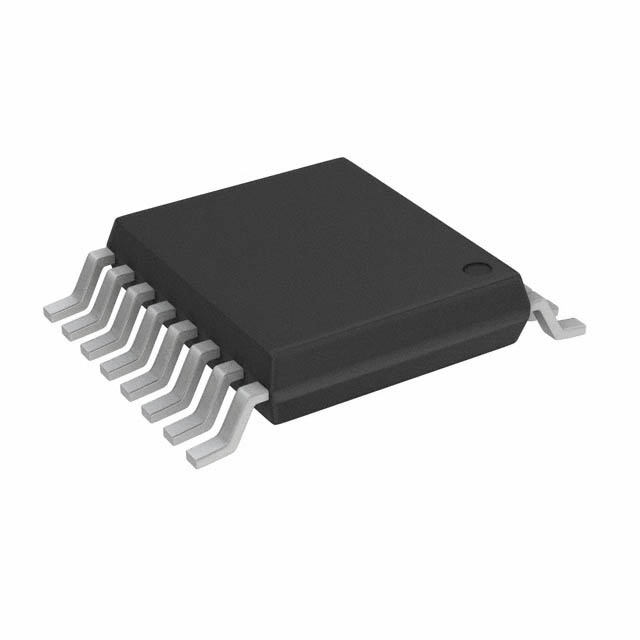
TSSOP16 package (SOT403-1), 5 mm × 4.4 mm × 1.1 mm body, 0.65 mm lead pitch. All pins are electrically validated per NXP datasheet Rev. 3.3 (July 2020).
| Pin/Terminal | Circuit Role | Design Meaning |
|---|---|---|
| 1 LA | Antenna connection (low-side) | Connects to one terminal of external LC antenna; forms resonant tank with LB |
| 3, 4, 13 GND | Ground reference | Three dedicated ground pins ensure stable RF and digital return paths; must be connected to PCB ground plane |
| 8 SDA/GPIO1/PWM1 | Multiplexed I2C data line | Primary I2C data path; also serves as GPIO or PWM output when I2C disabled |
| 9 SCL/GPIO0/PWM0 | Multiplexed I2C clock line | Primary I2C clock input; also usable as GPIO or PWM output |
| 10 ED/PWM0 | Event detection input | Triggers interrupt on external signal edge; shares PWM0 function but not simultaneously active |
| 11 VCC | External power supply | Accepts 1.62–5.5 V; powers internal logic and enables VOUT energy harvesting output |
| 12 HPD | Hard power-down control | Pull low to force ultra-low-power state (<0.25 µA); resets internal state on release |
| 14 VOUT | Energy harvesting output | Configurable regulated voltage output (up to 30 mW); powers external sensors or circuitry without battery |
| 16 LB | Antenna connection (high-side) | Completes resonant LC tank with LA; critical for 13.56 MHz field coupling and read range |
Key Features
| Feature | Design Value |
|---|---|
| NFC Forum Type 5 Tag compliance | Ensures interoperability with all certified NFC readers and mobile devices using standardized command set and memory layout |
| Zero-power I2C sensor readout | Enables passive, battery-free sensor interrogation via NFC tap - no local power source required during read operation |
| Three-zone memory protection | Allows independent password-based (32-/64-bit) or lock-based access control over user EEPROM, config area, and SRAM |
| Pass-through mode with SRAM | 256-byte SRAM acts as high-speed buffer between NFC reader and I2C slave, enabling real-time data relay without MCU intervention |
| Reprogrammable ECC originality signature | 32-byte signature stored in config memory verifies authenticity across supply chain; customer可 reprogram or lock permanently |
| Configurable energy harvesting | VOUT pin delivers stable, adjustable voltage (configurable via register) to power external components - reduces BoM and enables maintenance-free designs |
Applications
| Industrial Sensor Calibration | Smart Home Device Commissioning |
|---|---|
Use Scenario: Factory-floor calibration of temperature/humidity sensors before deployment. IC Role / Device Role / Timing Role: Acts as NFC-accessible I2C bridge to load calibration coefficients into sensor EEPROM via single tap. Use Value: Eliminates need for wired programming fixtures; enables rapid, error-resistant parameterization without opening enclosure. |
Use Scenario: On-site setup of lighting controllers or HVAC nodes by end-user tapping smartphone. IC Role / Device Role / Timing Role: Provides secure, standardized NFC interface to configure Wi-Fi credentials and device identity via NDEF message. Use Value: Reduces support calls and manual entry errors; leverages existing phone infrastructure instead of proprietary apps or QR codes. |
| Wearable Health Monitor Trimming | LED Driver Configuration |
Use Scenario: Final trimming of biosensor gain/offset after assembly to compensate for component tolerances. IC Role / Device Role / Timing Role: Stores trim values in protected EEPROM zone; accessed via NFC during final test without powering main MCU. Use Value: Enables post-assembly precision tuning without soldering or debug interfaces; supports high-volume automated test. |
Use Scenario: Dynamic adjustment of LED brightness/color profiles in architectural lighting systems. IC Role / Device Role / Timing Role: Bridges NFC commands to I2C-connected LED driver ICs; uses SRAM pass-through for real-time PWM updates. Use Value: Allows field technicians to update lighting behavior instantly via smartphone - no firmware flash or physical access needed. |
Equivalent & Alternatives
The following parts are listed as comparable options for similar NFC I2C bridge applications.
| Alternative Part | Technical Difference | Application Difference | Selection Advice |
|---|---|---|---|
| NTP53321G0JTTZ | Includes I2C master channel and 128-bit AES mutual authentication; same TSSOP16 package and pinout | Supports direct sensor readout without MCU; enables stronger cryptographic pairing in regulated environments | Select when transparent I2C master or AES-level security is required - otherwise NTP53121G0JTTZ offers lower cost and simpler integration |
| NT3H2211W0FHKZ | Smaller XQFN8 package; 1K EEPROM; no energy harvesting output or VOUT pin; supports I2C slave only | Limited to space-constrained, low-power consumer wearables; lacks VOUT-driven sensor powering capability | Choose for compact footprint and basic NFC tagging where energy harvesting and extended memory are unnecessary |
Compared with NTP53321G0JTTZ, NTP53121G0JTTZ omits AES and I2C master functions - reducing BOM cost and design complexity while retaining full NFC Type 5 compatibility, 2KB EEPROM, and VOUT energy harvesting. Versus NT3H2211W0FHKZ, it adds 1KB more EEPROM, VOUT capability, and TSSOP16 thermal robustness for industrial use.
Availability
NTP53121G0JTTZ is available at Aetrix Electronics and suitable for industrial sensor calibration, smart home commissioning, and wearable trimming applications requiring stable component supply, long-term lifecycle support, and traceable sourcing.
Supply support for NTP53121G0JTTZ includes scheduled delivery planning, volume procurement assistance, BOM continuity management, traceable sourcing, and lifecycle availability coordination for OEM customers, industrial embedded developers, connected-device designers, and electronics production programs.
Manufacturer
NXP Semiconductors is a global semiconductor leader specializing in secure connectivity solutions for automotive, industrial, and IoT markets, with deep expertise in NFC, RFID, and contactless interface technologies.
The NTAG 5 family - including NTP53121G0JTTZ - was designed specifically to enable battery-free, NFC-driven configuration and data acquisition in sensor-equipped edge devices, emphasizing interoperability, energy harvesting, and memory flexibility.
FAQ
What is the primary interface role of NTP53121G0JTTZ?
NTP53121G0JTTZ functions exclusively as an I2C slave device - it cannot act as an I2C master. It bridges NFC-initiated commands to an external I2C slave (e.g., sensor or memory) under control of a host MCU. This distinguishes it from the NTP5332 variant, which adds transparent I2C master capability. The NTP53121G0JTTZ relies on the host system to manage sensor communication.
Does NTP53121G0JTTZ support AES authentication?
No, NTP53121G0JTTZ does not support AES mutual authentication. That feature is exclusive to the NTP5332 series (e.g., NTP53321G0JTTZ). The NTP53121G0JTTZ implements password-based protection only - up to 64-bit NFC read/write passwords and 32-bit I2C passwords - with no hardware AES engine or associated key storage.
Can NTP53121G0JTTZ operate without an external power supply?
Yes, NTP53121G0JTTZ supports true zero-power operation using energy harvested from the NFC reader's RF field. When VCC is unpowered, the device draws energy from LA/LB antenna connections to power its RF interface and SRAM, enabling passive read/write and sensor data relay. VOUT remains inactive without VCC.
What memory types and capacities does NTP53121G0JTTZ provide?
NTP53121G0JTTZ integrates 2048 bytes of user EEPROM (16384 bits), 256 bytes of SRAM (2048 bits), and a separate configuration memory area. EEPROM guarantees 40-year data retention and 1 million write cycles. SRAM is volatile and accessible only when VCC is applied and SRAM_ENABLE is set - used for fast pass-through and dynamic pairing operations.
Is the NTP53121G0JTTZ pinout compatible with other NTAG 5 variants in TSSOP16?
Yes, NTP53121G0JTTZ shares identical TSSOP16 pinout, footprint, and electrical characteristics with NTP53321G0JTTZ - both use SOT403-1 package and match pin-for-pin on LA, LB, VCC, GND, SDA, SCL, ED, HPD, VOUT, and GPIO/PWM multiplexed functions. This allows drop-in replacement where AES or I2C master features are not required.
NTP53121G0JTTZ Specifications
- Product attributes
- Attribute value
- Manufacturer:
- NXP Semiconductors
- Series:
- -
- Packaging:
- Tape & Reel (TR)
- Product Status:
- Active
- Style:
- -
- Technology:
- -
- Frequency:
- 13.56MHz
- Memory Type:
- Read/Write
- Writable Memory:
- 16kb (User)
- Standards:
- ISO 15693, NFC
- Operating Temperature:
- -40°C ~ 85°C
- Size / Dimension:
- 0.173" L x 0.197" W (4.40mm x 5.00mm)
NTP53121G0JTTZ FAQ
1.How can I place an order for NTP53121G0JTTZ through Aetrix?
Please submit a Request for Quotation (RFQ) for NTP53121G0JTTZ on Aetrix. Our sales agent will provide a competitive quotation and guide you through the order confirmation once you accept the terms.
2.Are the price and stock information for NTP53121G0JTTZ reliable?
The price and inventory of NTP53121G0JTTZ are updated periodically and may fluctuate due to market conditions. Stock and pricing data are typically refreshed every 24 hours. Quotation validity for NTP53121G0JTTZ is usually 5 days.
3.What payment methods are accepted for NTP53121G0JTTZ?
We accept Wire Transfer, PayPal, Credit Card, Western Union, MoneyGram, and Escrow for NTP53121G0JTTZ transactions.
Note: Certain payment methods may incur a processing fee.
4.How is shipping managed for NTP53121G0JTTZ?
NTP53121G0JTTZ orders can be shipped via leading logistics carriers, including DHL, UPS, FedEx, TNT, or Registered Mail.
Once your NTP53121G0JTTZ order is processed, you will receive an email with the shipment details and tracking number.
Note: Tracking information may take up to 24 hours to appear. Express delivery typically takes 3–5 business days.
5.How can I obtain technical support or documentation for NTP53121G0JTTZ?
For technical support, including NTP53121G0JTTZ datasheets, pinout diagrams, or application guidance, please contact our engineering support team. They can provide detailed documentation and assistance for your NTP53121G0JTTZ requirements.
6.How does Aetrix verify that NTP53121G0JTTZ is sourced from the original manufacturer or authorized distributors?
All NTP53121G0JTTZ products on Aetrix are procured from qualified distributors and authorized channels. Our dedicated quality assurance team conducts strict verification, including traceability checks and, if necessary, third-party testing. This ensures that NTP53121G0JTTZ meets industry standards.
7.What is the process for return or replacement of NTP53121G0JTTZ?
All NTP53121G0JTTZ units undergo pre-shipment inspection (PSI). If there is an issue with NTP53121G0JTTZ, returns or replacements are accepted under the following conditions:
1.Quantity discrepancies, incorrect items, or visible external defects (such as breakage or corrosion), acknowledged by Aetrix.
2.The issue is reported within 90 days of delivery.
3.The NTP53121G0JTTZ part is unused and in its original packaging.
Return procedure for NTP53121G0JTTZ:
1.Submit a request within 90 days.
2.Obtain a Return Material Authorization (RMA) from Aetrix.
NTP53121G0JTTZ Tags
-
SL3S1013FTB0,115
NXP Semiconductors
-
NTP53321G0JHKZ
NXP Semiconductors
-
HTSH4801ETK,118
NXP Semiconductors
-
NTA53321G0FHKZ
NXP Semiconductors
-
RF-HDT-DVBE-N2
Texas Instruments
-
RF-HDT-DVBB-N2
Texas Instruments
-
HT2DC20S20/F/RSP
NXP Semiconductors
-
TRPGR30ATGA
Texas Instruments
-
TRPGR30ATGC
Texas Instruments
-
RI-TRP-DR2B-40
Texas Instruments
-
V680-D1KP52MT
Omron Automation and Safety
-
HTMS8001FTB/AF,115
NXP USA Inc.
Tech Hub

A practical engineering guide to 3.3V and 5V logic compatibility, input thresholds, resistor dividers, translator ICs, MOSFET level shifting, I2C pull-ups, timing limits and power-sequencing risks.

The 74HC595 uses push-pull logic outputs, while the TPIC6B595 uses 50 V open-drain DMOS sinks for higher-power loads. This guide compares timing, current limits, 3.3 V interfacing, load wiring, thermal…

The 74HC595 converts serial data into eight stable parallel outputs. This guide covers pin functions, shift and storage timing, OE and MR behavior, drive-current limits, cascading, voltage compatibilit…

A technical comparison of level-sensitive latches and edge-triggered flip-flops, covering timing windows, setup and hold limits, master–slave operation, time borrowing, race-through, HDL inference and…

A D latch stores one bit while Enable controls when data can pass. This reference covers gate-level operation, truth tables, transparency, setup and hold timing, LE versus OE, common ICs and practical …

An SR latch stores one bit through cross-coupled feedback. This engineering reference covers NOR and NAND implementations, truth tables, forbidden-state recovery, gated operation, switch debouncing, fa…

Latch circuits retain one bit through feedback. This technical reference covers SR and D latches, truth tables, transparency, timing limits, latch-versus-flip-flop behavior, applications and common log…

An engineering guide to LED driver operation, constant-current and constant-voltage outputs, linear and switching topologies, dimming, IC selection, calculations, replacement compatibility, and fault c…

Operational amplifier guide covering op amp basics, feedback, ideal vs real op amps, common configurations, buffer circuits, offset, bias current, gain-bandwidth, slew rate, rail-to-rail limits and sel…

Jumper cables guide covering safe connection order, red and black clamp placement, final ground connection, cable gauge, length, clamp quality, copper vs CCA cables, jump starter comparison and battery…


