
 My Inquiry
 My Account


Nexperia USA Inc. NXS0506UPZ
- Part No.:
- NXS0506UPZ
- Manufacturer:
- Nexperia USA Inc.
- Category:
- Translators, Level Shifters
- Package:
- Datasheet:
-
 NXS0506UPZ.pdf
- Description:
- IC TRANSLATOR BIDIR 16WLCSP
- Quantity:
- Payment:

- Shipping:

Inventory:3,696
Please send an inquiry. Send us your inquiry, and we will respond immediately.
Product details
Overview
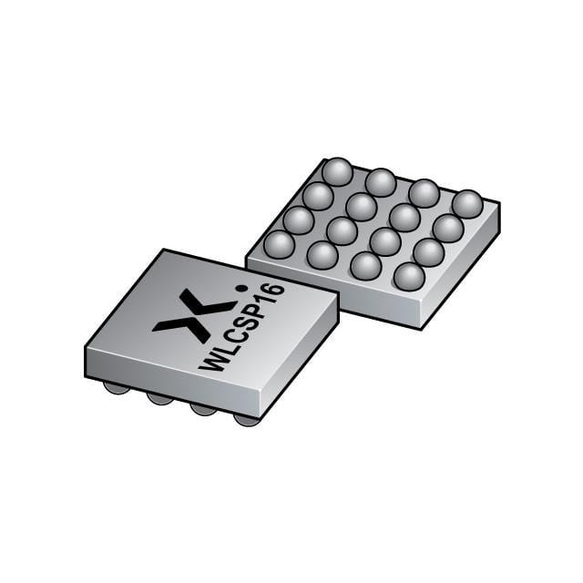
NXS0506UPZ from Nexperia is an SD 3.0-compatible bidirectional dual-supply level translator with integrated auto-direction control, EMI filtering, and IEC 61000-4-2 Level 4 ESD protection (8 kV contact / 15 kV air on memory card pins). It interfaces host systems (1.1 V–1.95 V) with SD/microSD/MMC cards (1.7 V–3.6 V), supports SDR104 (208 MHz), DDR50, and all legacy SD modes, and is packaged in a 1.455 × 1.455 × 0.43 mm WLCSP16 (SOT8025-1).
For engineers reviewing the NXS0506UPZ datasheet, NXS0506UPZ pinout, NXS0506UPZ application, or NXS0506UPZ equivalent, this page delivers verified electrical parameters, validated package mapping, confirmed SD 3.0 timing compliance, real-world ESD/EMI performance data, and precise pin-level circuit role definitions - all extracted from Nexperia's Rev. 4.1 product data sheet (July 2024).
Technical Context
The NXS0506UPZ implements auto-direction sensing logic that detects data flow direction (host→card or card→host) without external control signals, enabling seamless SD bus operation across SDR104, DDR50, and legacy modes. Its zero-clamping architecture routes ESD stress from memory card-side pins directly to GND, isolating the host interface.
It integrates 70 kΩ pull-up resistors on host-side I/Os (CMDA, DATnA, CLKA), eliminates need for external biasing, and includes dedicated CLKFB feedback path to compensate PCB trace delay - critical for maintaining timing margin during high-speed read operations at 208 MHz.
Key Specifications
| Parameter | Value and Actual Design Meaning |
|---|---|
| Max Clock Rate | 208 MHz - enables full SDR104 mode support per SD 3.0 specification. |
| Host Voltage Range | 1.1 V to 1.95 V - matches low-voltage mobile SoC I/O domains (e.g., 1.2 V/1.8 V rails). |
| Card Voltage Range | 1.7 V to 3.6 V - covers SD/microSD operating ranges including 1.8 V SDR and 3.3 V legacy modes. |
| ESD Protection (Card Side) | IEC 61000-4-2 Level 4: ≥8 kV contact / ≥15 kV air - meets industrial handheld reliability requirements. |
| Propagation Delay (DATnA→DATnB) | 1.7 ns to 5.4 ns - ensures timing closure in SDR104/DDR50 read/write paths at -40 °C to +85 °C. |
| Input Capacitance (Host Side) | 5 pF - minimizes signal loading on high-speed host controller outputs. |
| Auto-Enable Threshold | VCCB ≥ 0.9 V (enable) / ≤ 0.65 V (disable) - provides clean power sequencing with SD card insertion/removal. |
Pinout & Package
Package: WLCSP16 (SOT8025-1), 1.455 × 1.455 × 0.43 mm body, 0.35 mm bump pitch, backside coating applied. Designed for ultra-compact mobile PCB layouts with NSMD pad definition and micro-via grounding.
| Pin/Terminal | Circuit Role | Design Meaning |
|---|---|---|
| DAT2A (A1) | Host-side bidirectional data line 2 | Auto-sensed I/O for SD bus DAT2; connects to host controller DAT2 pin. |
| DAT3A (B1) | Host-side bidirectional data line 3 | Auto-sensed I/O for SD bus DAT3; supports 4-bit wide data transfers. |
| DAT0A (C1) | Host-side bidirectional data line 0 | Primary data lane; used in all SD modes including SDR104 and DDR50. |
| DAT1A (D1) | Host-side bidirectional data line 1 | Completes 4-bit data bus; identical internal structure to DAT0A–DAT3A for layout flexibility. |
| VCCA (A2) | Host-side supply voltage | Powers host-side buffers and logic; must be 1.1 V–1.95 V. |
| CMDA (B2) | Host-side command line | Bidirectional command channel; carries CMD signals in both directions with auto-direction control. |
| CLKFB (C2) | Host-side clock feedback | Provides delayed clock copy from card side to host for read-data timing compensation; can be left floating if unused. |
| CLKA (D2) | Host-side clock input | Receives master clock from host controller; drives CLKB to memory card. |
| VCCB (A3) | Memory card-side supply voltage | Powers card-side buffers; range 1.7 V–3.6 V; enables auto-enable when ≥0.9 V. |
| CMDB (B3) | Memory card-side command line | Connects to SD card CMD pin; robust 8 kV ESD protection prevents damage during hot-plug events. |
| GND (C3) | Supply ground | Common reference for both voltage domains; requires low-inductance connection to buried ground plane. |
| CLKB (D3) | Memory card-side clock output | Drives SD card CLK pin; output swing referenced to VCCB. |
| DAT2B (A4) | Memory card-side data line 2 | Connects to SD card DAT2; EMI-filtered and ESD-hardened for noisy card environments. |
| DAT3B (B4) | Memory card-side data line 3 | Supports high-speed 4-bit transfers; identical electrical specs to DAT2B/DAT0B/DAT1B. |
| DAT0B (C4) | Memory card-side data line 0 | Primary data lane on card side; handles command-response and data payloads in all SD modes. |
| DAT1B (D4) | Memory card-side data line 1 | Completes bidirectional 4-bit data path; interchangeable with DAT0B/DAT2B/DAT3B per layout needs. |
Key Features
| Feature | Design Value |
|---|---|
| Auto-direction sensing | Eliminates need for external DIR control signal; detects read/write direction dynamically via bus activity. |
| Integrated 70 kΩ pull-ups | Removes requirement for 4 external host-side pull-up resistors, reducing BOM count and PCB area. |
| Zero-clamping ESD architecture | Routes >8 kV ESD transients on card-side pins directly to GND, preventing voltage stress on host SoC I/Os. |
| Dedicated CLKFB feedback path | Compensates for PCB trace delay between CLKA and CLKB, preserving setup/hold margins during high-speed reads. |
| EMI-filtered I/O drivers | Reduces harmonic emissions from digital switching, easing RF coexistence in smartphone and tablet designs. |
Applications
| Smartphone SD Interface | Tablet PC microSD Slot |
|---|---|
Use Scenario: High-density mobile phone design integrating microSD slot with application processor operating at 1.2 V I/O voltage. IC Role / Device Role / Timing Role: Bidirectional level translator and ESD protector bridging 1.2 V host controller and 1.8 V microSD card; provides CLKFB-based timing compensation for SDR104 reads. Use Value: Enables 104 MB/s microSD transfer rates while meeting IEC 61000-4-2 Level 4 ESD immunity and minimizing PCB layer count via integrated pull-ups. | Use Scenario: 10-inch Android tablet requiring reliable hot-pluggable microSD expansion with minimal latency. IC Role / Device Role / Timing Role: Auto-direction-controlled voltage translator supporting DDR50 and SDR50 modes; manages VCCA/VCCB power sequencing during card insertion. Use Value: Guarantees glitch-free enumeration and sustained 50 MB/s throughput under thermal stress (-40 °C to +85 °C) with no external direction control logic. |
| Digital Camera Memory Card Slot | Laptop SD Card Reader |
Use Scenario: DSLR or mirrorless camera using UHS-I SD cards for burst-mode photo capture and 4K video recording. IC Role / Device Role / Timing Role: Level-shifting interface between 1.8 V FPGA-based host controller and 3.3 V SDHC/SDXC cards; provides EMI filtering to prevent image sensor noise coupling. Use Value: Maintains signal integrity at 100 MHz SDR50 clock rate while suppressing harmonics that could interfere with analog image processing circuits. | Use Scenario: Ultrabook with integrated SD card reader supporting SD 3.0 UHS-I speeds and backward compatibility with legacy SDHC cards. IC Role / Device Role / Timing Role: Dual-voltage translator enabling single hardware design to support both 1.8 V UHS-I and 3.3 V Default-Speed cards via automatic VCCB detection. Use Value: Reduces SKU complexity by allowing one reader design to handle all SD card generations without firmware reconfiguration. |
Equivalent & Alternatives
The following parts are listed as comparable options for similar SD card interface translation applications.
| Alternative Part | Technical Difference | Application Difference | Selection Advice |
|---|---|---|---|
| NXS0506GU | XQFN16 package (1.80 × 2.60 × 0.50 mm); 0.4 mm terminal pitch; no backside coating; higher thermal resistance than WLCSP. | Better suited for manual assembly or prototyping due to larger footprint and exposed terminals; less optimal for space-constrained mobile PCBs. | Select NXS0506GU when board-level rework or thermal testing is required; choose NXS0506UPZ for production smartphones/tablets. |
| TXS0108E | 8-channel auto-direction translator; supports 1.2 V–3.6 V translation but lacks SD-specific CLKFB, EMI filters, and IEC 61000-4-2 Level 4 ESD on card pins. | General-purpose level shifting only; not qualified for SD 3.0 timing or hot-plug ESD stress in consumer memory card slots. | Use TXS0108E for non-SD applications like GPIO expansion; avoid for certified SD/microSD implementations requiring SDR104 timing and robust ESD. |
Compared with NXS0506GU, the NXS0506UPZ offers superior board-area efficiency and ESD performance for mass-produced mobile devices; versus TXS0108E, it delivers SD-optimized features - CLKFB timing compensation, integrated EMI filtering, and certified card-side ESD protection - essential for reliable UHS-I operation.
Availability
NXS0506UPZ is available at Aetrix Electronics and suitable for smartphone SD interfaces, tablet microSD slots, digital camera memory card readers, and laptop SD card readers requiring stable component supply across extended temperature ranges and high-volume production cycles.
Supply support for NXS0506UPZ includes scheduled delivery planning, volume procurement assistance, BOM continuity management, traceable sourcing, and lifecycle availability coordination for OEM customers, industrial embedded developers, connected-device designers, and electronics production programs.
Manufacturer
Nexperia is a global semiconductor expert delivering high-performance, high-reliability logic, discrete, and MOSFET solutions optimized for mobile, computing, and automotive markets.
The NXS0506 product line targets SD/microSD interface challenges in portable electronics, specifically addressing voltage translation, ESD robustness, EMI suppression, and timing-critical clock feedback for UHS-I and SD 3.0 compliance.
FAQ
Can NXS0506UPZ support both SD 2.0 and SD 3.0 modes simultaneously?
No - the device operates in a single selected mode determined by host controller configuration. It supports all SD 2.0 (Default-Speed, High-Speed) and SD 3.0 (SDR12/25/50/104, DDR50) modes individually, but mode selection is handled externally by the host's SD controller firmware. The NXS0506UPZ transparently translates signals across the full voltage and timing range of each enabled mode.
Is CLKFB pin mandatory for functional operation?
No - CLKFB is optional. When unused, it may be left floating per datasheet guidance (Section 8.2). However, connecting CLKFB improves timing margin during high-speed read operations by compensating for CLKA-to-CLKB propagation delay; omitting it may limit achievable data rates in SDR104 or DDR50 modes under marginal PCB trace conditions.
What is the maximum allowable voltage difference between VCCA and VCCB?
VCCB must be ≥ VCCA per datasheet Table 6. No absolute maximum differential is specified, but recommended operating conditions require VCCB ≥ VCCA to ensure correct auto-direction logic operation and level translation integrity. Violating this condition risks undefined direction control behavior and potential data corruption on bidirectional lines.
Does NXS0506UPZ require external decoupling capacitors?
Yes - per Section 14.1 and Figure 5, two 4.7 µF ceramic capacitors are required: one between VCCA and GND, and another between VCCB and GND. These stabilize local supplies during high-frequency switching and reduce noise coupling between host and card domains. Placement within 2 mm of respective VCC pins is recommended for optimal EMI and transient response.
NXS0506UPZ Specifications
- Product attributes
- Attribute value
- Manufacturer:
- Nexperia USA Inc.
- Series:
- -
- Package/Case:
- Packaging:
- Tape & Reel (TR)
- Product Status:
- Obsolete
- Translator Type:
- Voltage Level
- Channel Type:
- Bidirectional
- Number of Circuits:
- 1
- Channels per Circuit:
- 6
- Voltage - VCCA:
- 1.1 V ~ 1.95 V
- Voltage - VCCB:
- 1.7 V ~ 3.6 V
- Input Signal:
- -
- Output Signal:
- -
- Output Type:
- Non-Inverted
- Data Rate:
- 104Mbps
- Operating Temperature:
- -40°C ~ 85°C (TA)
- Grade:
- -
- Qualification:
- -
- Features:
- -
- Mounting Type:
- Surface Mount
- Supplier Device Package:
- 16-XFBGA, WLCSP
NXS0506UPZ FAQ
1.How can I place an order for NXS0506UPZ through Aetrix?
Please submit a Request for Quotation (RFQ) for NXS0506UPZ on Aetrix. Our sales agent will provide a competitive quotation and guide you through the order confirmation once you accept the terms.
2.Are the price and stock information for NXS0506UPZ reliable?
The price and inventory of NXS0506UPZ are updated periodically and may fluctuate due to market conditions. Stock and pricing data are typically refreshed every 24 hours. Quotation validity for NXS0506UPZ is usually 5 days.
3.What payment methods are accepted for NXS0506UPZ?
We accept Wire Transfer, PayPal, Credit Card, Western Union, MoneyGram, and Escrow for NXS0506UPZ transactions.
Note: Certain payment methods may incur a processing fee.
4.How is shipping managed for NXS0506UPZ?
NXS0506UPZ orders can be shipped via leading logistics carriers, including DHL, UPS, FedEx, TNT, or Registered Mail.
Once your NXS0506UPZ order is processed, you will receive an email with the shipment details and tracking number.
Note: Tracking information may take up to 24 hours to appear. Express delivery typically takes 3–5 business days.
5.How can I obtain technical support or documentation for NXS0506UPZ?
For technical support, including NXS0506UPZ datasheets, pinout diagrams, or application guidance, please contact our engineering support team. They can provide detailed documentation and assistance for your NXS0506UPZ requirements.
6.How does Aetrix verify that NXS0506UPZ is sourced from the original manufacturer or authorized distributors?
All NXS0506UPZ products on Aetrix are procured from qualified distributors and authorized channels. Our dedicated quality assurance team conducts strict verification, including traceability checks and, if necessary, third-party testing. This ensures that NXS0506UPZ meets industry standards.
7.What is the process for return or replacement of NXS0506UPZ?
All NXS0506UPZ units undergo pre-shipment inspection (PSI). If there is an issue with NXS0506UPZ, returns or replacements are accepted under the following conditions:
1.Quantity discrepancies, incorrect items, or visible external defects (such as breakage or corrosion), acknowledged by Aetrix.
2.The issue is reported within 90 days of delivery.
3.The NXS0506UPZ part is unused and in its original packaging.
Return procedure for NXS0506UPZ:
1.Submit a request within 90 days.
2.Obtain a Return Material Authorization (RMA) from Aetrix.
NXS0506UPZ Tags
-
74LVC1T45GW,125
Nexperia USA Inc.
-
74LVCH2T45DC,125
Nexperia USA Inc.

-
SN74LVC1T45DBVR
Texas Instruments
-
SN74LVC1T45DRLR
Texas Instruments
-
SN74LVC1T45DPKR
Texas Instruments
-
SN74LVC2T45DCTR
Texas Instruments
-
74LVC2T45GT,115
Nexperia USA Inc.
-
SN74LVC1T45YZPR
Texas Instruments

-
LSF0102DCUR
Texas Instruments

-
SN74LVC1T45DCKR
Texas Instruments
-
TXS0102DCTR
Texas Instruments
-
FXLP34P5X
onsemi
Tech Hub

An engineering guide to LED driver operation, constant-current and constant-voltage outputs, linear and switching topologies, dimming, IC selection, calculations, replacement compatibility, and fault c…

Operational amplifier guide covering op amp basics, feedback, ideal vs real op amps, common configurations, buffer circuits, offset, bias current, gain-bandwidth, slew rate, rail-to-rail limits and sel…

Jumper cables guide covering safe connection order, red and black clamp placement, final ground connection, cable gauge, length, clamp quality, copper vs CCA cables, jump starter comparison and battery…

LDO regulator guide covering low dropout voltage, power dissipation, thermal design, PSRR, output noise, capacitor stability, adjustable LDO circuits, LDO vs buck converter and datasheet selection chec…

Conditional Access Module guide covering CAM meaning, CI/CI+ interface, smart card authorization, DVB security workflow, TV and set-top box compatibility, internal electronics, ESD protection, connecto…

Guide to electronic component obsolescence covering EOL risk, PCN/PDN notices, last-time buy planning, replacement options, form-fit-function validation, counterfeit risk and BOM lifecycle management.

18650 battery guide covering lithium-ion cell basics, 3.6V/3.7V voltage, 4.2V charging, mAh and Wh capacity, protected cells, chargers, BMS, series-parallel packs, holders, welding and sourcing checks.…

Hall effect sensor guide covering working principle, linear and digital sensors, Arduino circuits, current sensing, speed detection, automotive applications, A3144 examples, signal filtering and datash…

Product Change Notification guide for electronic components, covering PCN meaning, PCN vs PDN/EOL, common change types, risk levels, form-fit-function review, engineering validation, BOM control, LTB/L…

A practical guide to blend door actuators, covering HVAC function, symptoms, location, AC and heater issues, reset and calibration, replacement cost, electrical diagnosis, compatibility checks, and rep…


