
 My Inquiry
 My Account


Nexperia USA Inc. PBSS5560PA,115
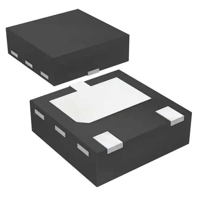
- Part No.:
- PBSS5560PA,115
- Manufacturer:
- Nexperia USA Inc.
- Category:
- Single Bipolar Transistors
- Package:
- 3-PowerUDFN
- Datasheet:
-
 PBSS5560PA,115.pdf
- Description:
- TRANS PNP 60V 5A 3HUSON
- Quantity:
- Payment:

- Shipping:

Inventory:4,380
Please send an inquiry. Send us your inquiry, and we will respond immediately.
Product details
Overview
PBSS5560PA,115 from Nexperia is a PNP low VCEsat Breakthrough In Small Signal (BISS) transistor in an ultra-thin leadless SOT1061 (HUSON3) package, rated for −60 V VCEO, −5 A continuous collector current, and 55–90 mΩ RCEsat at IC = −5 A / IB = −250 mA. It serves as a high-efficiency load switch in battery-powered power management circuits.
For engineers reviewing the PBSS5560PA,115 datasheet, PBSS5560PA,115 pinout, PBSS5560PA,115 application, or PBSS5560PA,115 equivalent, this device is selected for low-loss switching in compact DC-DC converters, motor drivers, and USB-C charging circuits where thermal performance and PCB area reduction are critical.
Technical Context
This PNP BISS transistor uses a proprietary epitaxial structure to achieve ultra-low saturation resistance while maintaining robust breakdown voltage and thermal stability. Its exposed collector pad enables direct thermal coupling to PCB copper, supporting up to 2.1 W dissipation on ceramic substrates.
The device operates with DC current gain (hFE) of 90–135 at IC = −5 A and exhibits fast switching: ton = 88 ns, toff = 410 ns under VCC = −9 V, IC = −2 A conditions - optimized for medium-frequency PWM control in portable power systems.
Key Specifications
| Parameter | Value and Actual Design Meaning |
|---|---|
| VCEO | −60 V - Withstands reverse-biased collector-emitter voltage up to 60 V in open-base configuration, enabling use in 48 V rail switching. |
| IC | −5 A - Continuous collector current rating supports high-current load switching without derating at Tamb ≤ 25 °C on 6 cm² FR4 copper. |
| RCEsat | 55–90 mΩ - Low saturation resistance minimizes conduction loss (Ploss ≈ 1.4 mW/A²), critical for efficiency in battery-driven devices. |
| toff | 410 ns - Fast turn-off time allows operation up to ~250 kHz PWM without significant switching loss accumulation. |
| Ptot | 2.1 W - Maximum power dissipation on Al2O3 ceramic PCB, enabling higher current density than conventional SOT23/SOT223 alternatives. |
| Rth(j-a) | 60 K/W - Junction-to-ambient thermal resistance on ceramic substrate ensures Tj stays below 150 °C at full load with minimal heatsinking. |
| hFE | 90–135 @ IC = −5 A - Sufficient DC gain for direct microcontroller GPIO drive (IB = −250 mA) without external amplification. |
Pinout & Package
Package: SOT1061 (HUSON3), ultra-thin 2.0 × 2.0 × 0.65 mm leadless plastic package with exposed collector thermal pad.
| Pin/Terminal | Circuit Role | Design Meaning |
|---|---|---|
| 1 | Base | Control input terminal; accepts −250 mA base drive for full saturation at −5 A collector current. |
| 2 | Emiter | Reference node for PNP operation; connected to higher potential rail (e.g., battery +) in high-side switch configurations. |
| 3 | Collector | Power output terminal with exposed metal pad; electrically and thermally connected to PCB copper for low-inductance, high-power routing. |
Key Features
| Feature | Design Value |
|---|---|
| Low VCEsat | VCEsat = −280 to −450 mV @ IC = −5 A - Reduces voltage drop and self-heating in high-current load paths. |
| Exposed collector pad | Thermal resistance as low as 60 K/W on ceramic PCB - Enables passive cooling in space-constrained battery packs and wearables. |
| Ultra-thin SMD footprint | 2.0 × 2.0 mm body size - Saves >50% PCB area vs. SOT223, critical for ultra-portable charging ICs and PMIC modules. |
| High peak current capability | ICM = −6 A (1 ms pulse) - Supports inrush current handling in motor startup and hot-swap applications. |
Applications
| Load Switching | Battery Protection Circuits |
|---|---|
Use Scenario: High-side power switch controlling 12–48 V loads in industrial handheld tools. IC Role / Device Role / Timing Role: PNP BISS transistor operating in saturation mode as main current path switch, driven by MCU GPIO. Use Value: 55 mΩ RCEsat limits voltage drop to <0.28 V at 5 A, preserving battery runtime and reducing thermal stress on adjacent components. |
Use Scenario: Reverse-polarity and overcurrent protection in USB-C PD power banks. IC Role / Device Role / Timing Role: PNP switch placed between battery and system rail, activated only when polarity and current thresholds are validated. Use Value: −60 V VCEO withstands accidental reverse connection; fast toff (410 ns) enables rapid fault isolation before damage occurs. |
| DC-DC Converter Sync Rectification | Motor/Fan Power Control |
Use Scenario: Low-side synchronous rectifier in 5–24 V buck converter for IoT edge nodes. IC Role / Device Role / Timing Role: PNP transistor used in complementary topology with N-channel MOSFET to reduce forward conduction loss during light-load operation. Use Value: 90–135 hFE ensures stable gate drive current delivery without external buffer, simplifying gate control circuitry. |
Use Scenario: PWM-controlled fan driver in automotive cabin controllers and medical cooling units. IC Role / Device Role / Timing Role: Medium-power PNP switch modulating 2–5 A fan current at 20–100 kHz PWM frequency. Use Value: 88 ns ton/410 ns toff enables clean PWM edges with minimal shoot-through risk and audible noise suppression. |
Equivalent & Alternatives
The following parts are listed as comparable options for similar PNP low-VCEsat transistor applications.
| Alternative Part | Technical Difference | Application Difference | Selection Advice |
|---|---|---|---|
| DMT3007LPSQ-13 | PNP, −30 V VCEO, −4.5 A IC, RCEsat = 75–110 mΩ - lower voltage rating, larger SOT23-3 package. | Limited to ≤30 V systems; lacks exposed thermal pad, limiting power handling in sustained 4 A operation. | Select when cost sensitivity outweighs thermal performance and board space constraints. |
| PBSS5350PAS,115 | PNP, −50 V VCEO, −3.5 A IC, RCEsat = 85–130 mΩ - lower current/voltage, same SOT1061 package. | Insufficient for 5 A continuous loads; suitable only for sub-3 A battery switches or backup power paths. | Choose only if design requires footprint compatibility but operates below 3 A average current. |
Compared with DMTC3007LPSQ-13 and PBSS5350PAS,115, PBSS5560PA,115 delivers 17% higher voltage margin, 43% higher continuous current, and 30% lower RCEsat in the same ultra-compact footprint - making it the sole option for 48 V, 5 A load switching with thermal headroom.
Availability
PBSS5560PA,115 is available at Aetrix Electronics and suitable for battery-driven devices, power management subsystems, and motor/fan power switches requiring stable component supply across industrial, computing, and consumer product lifecycles.
Supply support for PBSS5560PA,115 includes scheduled delivery planning, volume procurement assistance, BOM continuity management, traceable sourcing, and lifecycle availability coordination for OEM customers, industrial embedded developers, connected-device designers, and electronics production programs.
Manufacturer
Nexperia is a global leader in discrete, logic, and PowerMOS semiconductors, spun off from NXP in 2017 and focused on high-volume, high-reliability components for automotive, industrial, and consumer markets.
PBSS5560PA,115 belongs to Nexperia's BISS transistor family, engineered specifically for high-efficiency, space-constrained power switching in portable and battery-operated equipment.
FAQ
Is PBSS5560PA,115 automotive qualified?
No. PBSS5560PA,115 is not AEC-Q101 qualified and lacks automotive-grade screening, temperature cycling, or humidity testing. It is intended for industrial, computing, and consumer applications per its datasheet specification and Nexperia's non-automotive product classification.
What is the maximum allowable base current for continuous operation?
The absolute maximum base current is −600 mA per Table 5 (Limiting Values). For reliable long-term operation at IC = −5 A, Nexperia specifies IB = −250 mA in the RCEsat test condition - exceeding this risks thermal runaway or accelerated degradation.
Can PBSS5560PA,115 be used in linear regulator pass elements?
No. Its RCEsat is optimized for saturation-mode switching, not linear operation. The device lacks safe operating area (SOA) characterization for linear use, and its thermal resistance assumes pulsed or switched duty cycles - not continuous DC bias.
Does the SOT1061 package require special reflow profile considerations?
Yes. Per Section 11 of the datasheet, only reflow soldering is recommended. The ultra-thin 0.65 mm profile and exposed thermal pad demand precise stencil aperture design (0.25 mm thickness, 0.4 mm openings) and controlled ramp rates to avoid tombstoning or voiding under the collector pad.
PBSS5560PA,115 Specifications
- Product attributes
- Attribute value
- Manufacturer:
- Nexperia USA Inc.
- Series:
- -
- Package/Case:
- 3-PowerUDFN
- Packaging:
- Tape & Reel (TR)
- Product Status:
- Active
- Transistor Type:
- PNP
- Current - Collector (Ic) (Max):
- 5 A
- Voltage - Collector Emitter Breakdown (Max):
- 60 V
- Vce Saturation (Max) @ Ib, Ic:
- 450mV @ 250mA, 5A
- Current - Collector Cutoff (Max):
- 100nA
- DC Current Gain (hFE) (Min) @ Ic, Vce:
- 150 @ 2A, 2V
- Power - Max:
- 2.1 W
- Frequency - Transition:
- 90MHz
- Operating Temperature:
- 150°C (TJ)
- Grade:
- -
- Qualification:
- -
- Mounting Type:
- Surface Mount
- Supplier Device Package:
- 3-HUSON (2x2)
PBSS5560PA,115 FAQ
1.How can I place an order for PBSS5560PA,115 through Aetrix?
Please submit a Request for Quotation (RFQ) for PBSS5560PA,115 on Aetrix. Our sales agent will provide a competitive quotation and guide you through the order confirmation once you accept the terms.
2.Are the price and stock information for PBSS5560PA,115 reliable?
The price and inventory of PBSS5560PA,115 are updated periodically and may fluctuate due to market conditions. Stock and pricing data are typically refreshed every 24 hours. Quotation validity for PBSS5560PA,115 is usually 5 days.
3.What payment methods are accepted for PBSS5560PA,115?
We accept Wire Transfer, PayPal, Credit Card, Western Union, MoneyGram, and Escrow for PBSS5560PA,115 transactions.
Note: Certain payment methods may incur a processing fee.
4.How is shipping managed for PBSS5560PA,115?
PBSS5560PA,115 orders can be shipped via leading logistics carriers, including DHL, UPS, FedEx, TNT, or Registered Mail.
Once your PBSS5560PA,115 order is processed, you will receive an email with the shipment details and tracking number.
Note: Tracking information may take up to 24 hours to appear. Express delivery typically takes 3–5 business days.
5.How can I obtain technical support or documentation for PBSS5560PA,115?
For technical support, including PBSS5560PA,115 datasheets, pinout diagrams, or application guidance, please contact our engineering support team. They can provide detailed documentation and assistance for your PBSS5560PA,115 requirements.
6.How does Aetrix verify that PBSS5560PA,115 is sourced from the original manufacturer or authorized distributors?
All PBSS5560PA,115 products on Aetrix are procured from qualified distributors and authorized channels. Our dedicated quality assurance team conducts strict verification, including traceability checks and, if necessary, third-party testing. This ensures that PBSS5560PA,115 meets industry standards.
7.What is the process for return or replacement of PBSS5560PA,115?
All PBSS5560PA,115 units undergo pre-shipment inspection (PSI). If there is an issue with PBSS5560PA,115, returns or replacements are accepted under the following conditions:
1.Quantity discrepancies, incorrect items, or visible external defects (such as breakage or corrosion), acknowledged by Aetrix.
2.The issue is reported within 90 days of delivery.
3.The PBSS5560PA,115 part is unused and in its original packaging.
Return procedure for PBSS5560PA,115:
1.Submit a request within 90 days.
2.Obtain a Return Material Authorization (RMA) from Aetrix.
PBSS5560PA,115 Tags

-
MMBT3906LT1G
onsemi
-
MMBT3904-7-F
Diodes Incorporated
-
MMBT3904LT1G
onsemi
-
MMBT3906-7-F
Diodes Incorporated
-
MMBT3904-TP
Micro Commercial Co
-
MMBT2222A-7-F
Diodes Incorporated

-
BC846BLT1G
onsemi
-
BC847B,215
Nexperia USA Inc.
-
SMMBT3904LT1G
onsemi
-
MMBT2222A-TP
Micro Commercial Co
-
MMBTA06LT1G
onsemi
-
MMBT2222ALT1G
onsemi
Tech Hub

A practical engineering guide to 3.3V and 5V logic compatibility, input thresholds, resistor dividers, translator ICs, MOSFET level shifting, I2C pull-ups, timing limits and power-sequencing risks.

The 74HC595 uses push-pull logic outputs, while the TPIC6B595 uses 50 V open-drain DMOS sinks for higher-power loads. This guide compares timing, current limits, 3.3 V interfacing, load wiring, thermal…

The 74HC595 converts serial data into eight stable parallel outputs. This guide covers pin functions, shift and storage timing, OE and MR behavior, drive-current limits, cascading, voltage compatibilit…

A technical comparison of level-sensitive latches and edge-triggered flip-flops, covering timing windows, setup and hold limits, master–slave operation, time borrowing, race-through, HDL inference and…

A D latch stores one bit while Enable controls when data can pass. This reference covers gate-level operation, truth tables, transparency, setup and hold timing, LE versus OE, common ICs and practical …

An SR latch stores one bit through cross-coupled feedback. This engineering reference covers NOR and NAND implementations, truth tables, forbidden-state recovery, gated operation, switch debouncing, fa…

Latch circuits retain one bit through feedback. This technical reference covers SR and D latches, truth tables, transparency, timing limits, latch-versus-flip-flop behavior, applications and common log…

An engineering guide to LED driver operation, constant-current and constant-voltage outputs, linear and switching topologies, dimming, IC selection, calculations, replacement compatibility, and fault c…

Operational amplifier guide covering op amp basics, feedback, ideal vs real op amps, common configurations, buffer circuits, offset, bias current, gain-bandwidth, slew rate, rail-to-rail limits and sel…

Jumper cables guide covering safe connection order, red and black clamp placement, final ground connection, cable gauge, length, clamp quality, copper vs CCA cables, jump starter comparison and battery…


